Viessmann Vitosol 300-T Installation Instructions For Contractors
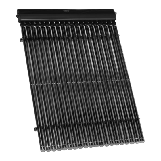
Vacuum tube collector based on the heat pipe principle
Hide thumbs
Also See for Vitosol 300-T:
- Installation instructions manual (36 pages) ,
- Technical manual (144 pages) ,
- Domestic product manual (56 pages)

Related Manuals for Viessmann Vitosol 300-T


Summary of Contents for Viessmann Vitosol 300-T
- Page 1 VIESMANN Installation instructions for contractors Vitosol 300-T Type SP3A Vacuum tube collector based on the heat pipe principle VITOSOL 300-T Dispose after installation. 5369 537 GB 9/2009...
- Page 2 Safety instructions Please follow these safety instructions closely to prevent accidents and mate- rial losses. Safety instructions explained Working on the system Danger ■ Isolate the system from the power sup- This symbol warns against the ply and check that it is no longer 'live', risk of injury.
-
Page 3: Table Of Contents
Index Preparing for installation Observe prior to installation.................. Installation sequence Installation with rafter anchors................Installation with fixing brackets................14 Installing the header casing.................. 17 Making the hydraulic connections................ 17 ■ Connecting the header casing................17 ■ Fitting the connection set.................. 19 ■... -
Page 4: Observe Prior To Installation
Observe prior to installation For each number of collectors and col- The following tables detail the rafters on lector combination, a specific number of which the rafter anchors or mounting rafter anchors or fixing brackets (in con- brackets should be fitted. nection with sheet steel roofs) is alloca- ted. - Page 5 Observe prior to installation (cont.) Always maintain the following dimen- sions: ■ Dimension b, projection of the mount- ing rails with tube holders, see the fol- lowing tables ■ Dimension c = 81 mm 1 collector Combination Rafter distance a Rafters used b in mm in mm...
- Page 6 Observe prior to installation (cont.) 3 collectors Combination Rafter distance a Rafters used b in mm in mm ≤ 600 1, 2, 3, 5, 6, 8 2 x 2 m ≤ 700 1, 2, 3, 4, 5, 7 1 x 3 m ≤...
-
Page 7: Installation With Rafter Anchors
Installation with rafter anchors Components / 2 1 / 2 1 Ø8,4 M8x25 Overview... - Page 8 Installation with rafter anchors (cont.) 1360 Installation...
- Page 9 Installation with rafter anchors (cont.) Dimension a = 1650 mm...
- Page 10 Installation with rafter anchors (cont.)
- Page 11 Installation with rafter anchors (cont.)
- Page 12 Installation with rafter anchors (cont.)
- Page 13 Installation with rafter anchors (cont.) 90° 90° Dimension c = 81 mm...
-
Page 14: Installation With Fixing Brackets
Installation with rafter anchors (cont.) Note Tube holders on opposite rails must be aligned. 90° Continue installing the header casing (see page 17). Installation with fixing brackets For example, installation on sheet steel roofs. - Page 15 Installation with fixing brackets (cont.) Components Ø8,4 M8x25 / 2 1 / 2 1 Overview 1360...
- Page 16 Installation with fixing brackets (cont.) Installation Use on-site fixing elements to secure the The installation of the mounting bracket brackets. is shown using an upstanding profile as an example. 90° 90° Continue with step 20 on page 13.
-
Page 17: Installing The Header Casing
Installing the header casing 90° 90° Note The tube holders on the mounting rails must be aligned with those in the header casing; where necessary, align with a piece of string. Making the hydraulic connections Connecting the header casing Components... - Page 18 Making the hydraulic connections (cont.) Installation information Lubricate all O-ring seals only ■ with the special grease provi- Please note ded. Connection pipes should not show any signs of damage. ■ Click retaining clips into the groove in the connection pipes through the holes in the collector connectors.
-
Page 19: Fitting The Connection Set
Making the hydraulic connections (cont.) Fitting the connection set Components Installation information ■ Initially turn the union nut by hand, ■ All pipes must be cut at a right angle then tighten with an open ended span- and deburred. ner by a further ¾ turn. ■... - Page 20 Making the hydraulic connections (cont.) 2. 2x ■ Click retaining clips into the groove through the holes in the collector con- nectors. ■ After joining the collector array to the pipework of the solar circuit, fill the system, check the system pressure and test for leaks.
-
Page 21: Fitting The Vacuum Tubes
Making the hydraulic connections (cont.) Fitting the vacuum tubes Danger ■ The condenser must be positioned The vacuum tubes can become centrally inside the heat exchanger hot and break if insufficient care retainer. is taken. This can lead to burns ■... -
Page 22: Fitting The Collector Temperature Sensor
Making the hydraulic connections (cont.) Note When installing the tubes, make sure that the locking pins for each tube are opened and closed separately. Fitting the collector temperature sensor Installation information Please note ■ The first and last tubes of a collector Route the sensor lead so that it must be secured to the twin-pipe heat does not come into contact with... - Page 23 Fitting the collector temperature sensor (cont.) 1. 2x...
-
Page 24: Installation
Installation Please note 3. The expansion vessel must be Incorrect installation can lead to approved to DIN 4807 [or local regu- collector damage. lations] and must be installed with a Use only gunmetal or brass fit- thermal insulating loop. The dia- tings and copper pipes for the phragms and seals of the expansion installation. -
Page 25: Commissioning And Adjustment
Installation (cont.) A Collector H Manual solar fill pump B Solar-Divicon K Fill valve (F, G, L) C Drip container L Drain D Expansion vessel M Air separator E Stagnation heat sink N DHW cylinder F Shut-off valve O Solar control unit G Filling facility P Air vent valve Commissioning and adjustment... - Page 28 Viessmann Werke GmbH&Co KG Viessmann Limited D-35107 Allendorf Hortonwood 30, Telford Telephone: +49 6452 70-0 Shropshire, TF1 7YP, GB Fax: +49 6452 70-2780 Telephone: +44 1952 675000 www.viessmann.com Fax: +44 1952 675040 E-mail: info-uk@viessmann.com...
Need help?
Do you have a question about the Vitosol 300-T and is the answer not in the manual?
Questions and answers