Viessmann Vitosol 300-T Installation Instructions Manual
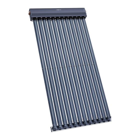
Vacuum tube collector based on the heat pipe principle type sp3a
Hide thumbs
Also See for Vitosol 300-T:
- Installation instructions manual (32 pages) ,
- Installation instructions for contractors (28 pages) ,
- Technical manual (144 pages)

Related Manuals for Viessmann Vitosol 300-T


Summary of Contents for Viessmann Vitosol 300-T
-
Page 1: Installation Instructions
VIESMANN Installation instructions for contractors Vitosol 300-T Type SP3A Vacuum tube collector based on the heat pipe principle VITOSOL 300-T Dispose after installation. 5366 351 GB 8/2008... - Page 2 Safety instructions Please follow these safety instructions closely to prevent accidents and material losses. Safety instructions explained Regulations Danger Observe the following when working This symbol warns against the on this system risk of injury. & all legal instructions regarding the prevention of accidents, Please note &...
-
Page 3: Table Of Contents
Index Preparing for installation................Installation sequence Vertical rooftop installation................& Component overview ................& Fitting roof hooks or mounting brackets ............ & Fitting mounting rails................13 & Fitting the connecting chamber ..............16 Installation on flat roofs ................17 & Component overview ................ -
Page 4: Preparing For Installation
Preparing for installation Earthing and lightning protection of the solar heating system Install an electrical conductor on the The connection of the collector sys- pipework system of the solar circuit in tem to a new or existing lightning pro- the lower part of the building in com- tection system or the provision of pliance with VDE [or local regula- local earthing must only be carried out... -
Page 5: Vertical Rooftop Installation
Vertical rooftop installation Component overview Roof tile cover Slate cover 1 Timber 5 Roof hooks 6 Zinc-plated countersunk chip- & 38 x 58 x 2140 mm & 30 x 100 x 2140 mm board screw (Spax-s) 6 x 30 mm 2 Roof hooks 3 Zinc-plated countersunk chip- Corrugated sheet cover... - Page 6 Vertical rooftop installation (cont.) qE Washer Plain tile cover 9 Roof hooks qR Hexagon nut 4 Zinc-plated countersunk chip- qT Mounting rail qZ Mounting rail with tube holders board screw (Spax-s) 5 x 30 mm qU Retaining plate qI Connecting casing Fixing without roof hooks qP Mounting bracket qO Vacuum tube...
-
Page 7: Fitting Roof Hooks Or Mounting Brackets
Vertical rooftop installation (cont.) Fitting roof hooks or mounting brackets Overview – Installation with roof hooks E Roof hooks Dimension x according to the width of F Timber, 38 x 58 mm the tile head. (only for roof tiles) A Vacuum tube G Timber, 30 x 100 mm B Clamping bracket (only for roof tiles) - Page 8 Vertical rooftop installation (cont.) Use on-site fixing elements to secure the brackets (for example standing seams). A Vacuum tube E Mounting rail B Clamping bracket F Retaining plate C Mounting rail with tube holders G Connecting casing D Mounting bracket...
- Page 9 Vertical rooftop installation (cont.) For installations without roof hooks, mounting brackets are used in place of the roof hooks. Note Centre the mounting rails; maintain dimension f = 81 mm. Combination mm b mm c mm d mm e — —...
- Page 10 Vertical rooftop installation (cont.) Fitting the mounting brackets Secure the mounting brackets to the substructure on-site in accordance with the dimensions given in the illus- trations on page 7 and 9. Fitting roof hooks for roof tile cover 1. Push up the roof tiles in accor- 2.
- Page 11 Vertical rooftop installation (cont.) 3. Hook the roof hooks into the timber 5. Secure the roof hooks and position in accordance with the dimensions the roof tiles. shown in the illustration on page 9. Continue with "Mounting rail instal- lation" on page 13. 4.
- Page 12 Vertical rooftop installation (cont.) Fitting roof hooks for corrugated sheet cover 1. Mark the position of the roof hooks in accordance with the dimensions shown in the illustration on page 7 and 9. 2. Position each roof hook at the level of a batten onto the ridge of the roofing sheet and, through the hole in the roof hook, drill a further hole...
-
Page 13: Fitting Mounting Rails
Vertical rooftop installation (cont.) 5. Cover the roof; trim tiles to suit with an angle grinder; trim approx. 30 mm off the tiles. Fitting mounting rails Turn the tee bolts 90° for all installation steps. 1. Secure the mounting rails to the roof hooks or mounting brackets;... - Page 14 Vertical rooftop installation (cont.) 2. Align and fix the retaining plates to the mounting rails.
- Page 15 Vertical rooftop installation (cont.) Note Centre the mounting rails; maintain dimension f = 81 mm. 3. Fit clamping brackets onto the mounting rails; do not yet tighten the bolts. 4. Click the mounting rails with tube holders into the clamping brackets; align and fasten.
-
Page 16: Fitting The Connecting Chamber
Vertical rooftop installation (cont.) Fitting the connecting chamber Turn the tee bolts 90° for all installation steps. 1. Position the connecting chamber 3. Tighten the connecting chamber onto the mounting rails and click with the clamping brackets. into the retaining plates. 4. -
Page 17: Installation On Flat Roofs
Installation on flat roofs Component overview... -
Page 18: Determining The Collector Row Distance "Z
Installation on flat roofs (cont.) A Collector supports for angles of inclination α 25 to 50°, pre- assembled with screws, washers, nuts and clamping brackets 1 Collector support 7 Washer 7 8.4 mm 2 Horizontal base supports 8 Hexagon nut M 8 3 Adjustable support, lower part qZ Mounting rail with tube holders 4 Adjustable support, upper part... -
Page 19: Adjusting The Angle Of Inclination Α
Installation on flat roofs (cont.) 1. Determine the angle of the sun β. 2. Calculating dimension z: In Germany this angle (subject to h = 2165 mm α = 45 ° latitude) lies between 12 ° (Flens- β = 16.5 ° burg) and 20 °... -
Page 20: Fitting The Collector Supports
Installation on flat roofs (cont.) 1. Secure the adjustable support with 2. Secure the upper and lower adjus- the horizontal base supports. table supports in accordance with the required angle of inclination (see page 18). Fitting the collector supports Ballast and max. load on the substructure Calculation in accordance with DIN 1055-4, 8/1986 and DIN 1055-5, 6/1975... - Page 21 Installation on flat roofs (cont.) Collector angle of inclination 25 ° Protection against slip- Protection against lifting page Installation m <8 8–20 <8 8–20 height above ground Collector type Weight per foot support A Weight per foot support B Collector angle of inclination 45 ° Protection against slip- Protection against lifting page...
- Page 22 Installation on flat roofs (cont.) Note To calculate dimension z, see page 18. A Foot support A B Foot support B Combination mm b /2 m 900/900 /3 m 900/1200 /3 m 1200/1200 1031...
- Page 23 Installation on flat roofs (cont.) 1. Observe the max. load and dis- 2. Clear the position for installation, tance from the edge of the roof for for example of gravel, lay out the the on-site substructure in accor- protective mats and position foot dance with DIN 1055.
-
Page 24: Fitting The Mounting Rails And Connecting Chamber
Installation on flat roofs (cont.) 6. Drill 8.5 mm 7 holes into the cross braces and connect braces together. Fitting the mounting rails and connecting chamber... -
Page 25: Hydraulic Connections
Installation on flat roofs (cont.) 1. Click and fasten the mounting rails 4. Tighten all screws. into clamping brackets. 5. Where several collectors are 2. Click the connecting chamber into installed side-by-side, continue the clamping brackets. with "Connecting the connecting chamber"... -
Page 26: Fitting The Connection Set
Hydraulic connections (cont.) A Nut for the retaining clip Connecting pipes should not show 4. Secure the connecting pipes with any signs of damage. retaining clips; click clips into the Lubricate all plug-in connectors (O- groove in the connecting pipes rings) found on the collectors only through the holes in the collector with the special grease supplied with... - Page 27 Hydraulic connections (cont.) A Nut for the retaining clip VL Flow (short connecting pipe) RL Return (long connection pipe) 1. Remove the retaining clips. 5. Thread the locking ring fittings onto the connecting pipe. 2. Push the connecting pipes in as far as possible.
-
Page 28: Fitting The Vacuum Tubes And Collector Temperature Sensor
Hydraulic connections (cont.) 7. Check the system pressure and 8. Fit the thermal insulation cap. test for leaks. "Vitosol" service instruc- tions. Fitting the vacuum tubes and collector temperature sensor Danger The vacuum tubes can become hot and break if insufficient care is taken. - Page 29 Hydraulic connections (cont.) A Dual-pipe heat exchanger B Condenser C Template 4. Turn the locking pin together with 5. Click the tubes into the tube the installation pipe 90°. holders on the mounting rails and insert the condenser into the dual- pipe heat exchanger.
- Page 30 Hydraulic connections (cont.) Please note 7. Move the locking pin. Never align (turn) the tubes in their locked state. 8. Secure the tubes with the retain- This would lead to tube ing rubber. damage. For south-facing roofs, adjust the angle of inclination of the absor- ber using the enclosed template.
- Page 31 Hydraulic connections (cont.) A Dual-pipe heat exchanger D Clip 9. The first and last tubes of a col- 13. Route the lead inside the slot of lector must be secured to the the thermal insulation so that it dual-pipe heat exchanger with a does not come into contact with clip.
-
Page 32: Installation
Installation Please note Incorrect installation can lead to collector damage. Use only gunmetal or brass fittings and copper pipes for the installation. Use hemp only in conjunction with pressure and temperature-resistant sealants (e.g. Viscotex Solarpaste from Locher, CH-9450 Altstätten, Switzerland). Never step onto solar panels. - Page 33 Installation (cont.) A Collector H Manual solar fill pump B Solar-Divicon K Fill valve (F, G, L) C Drip container L Drain D Expansion vessel M Air separator E Pre-cooling vessel N DHW cylinders F Shut-off valve O Solar control unit G Filling facility P Air vent valve...
-
Page 34: Commissioning And Adjustment
Commissioning and adjustment For commissioning of the solar heating system, see the "Vitosol" service instructions. - Page 36 Viessmann Werke GmbH&Co KG Viessmann Limited D-35107 Allendorf Hortonwood 30, Telford Telephone: +49 6452 70-0 Shropshire, TF1 7YP, GB Fax: +49 6452 70-2780 Telephone: +44 1952 675000 www.viessmann.com Fax: +44 1952 675040 E-mail: info-uk@viessmann.com...
Need help?
Do you have a question about the Vitosol 300-T and is the answer not in the manual?
Questions and answers