
Related Manuals for Quantronix CubiScan 125


Summary of Contents for Quantronix CubiScan 125
- Page 1 CubiScan ® Operations and Technical Manual Version 1.1 Quantronix, Inc. Cubing and Weighing Systems 380 South 200 West P.O. Box 929 Farmington, Utah 84025 U. S. A. Phone (801) 451-7000 Fax (801) 451-0502 email: info@cubiscan.com...
- Page 2 CubiScan 125 measurement products incorporate technology protected by patents pending. This document copyright © 2011 by Quantronix, Inc. All rights reserved. No portion of this manual may be reproduced in any form without written permission from Quantronix, Inc. Information in this manual is subject to change without notice.
- Page 3 Statement of Warranty. Subject and according to the Terms and Conditions set forth below, Quantronix, Inc., (hereafter referred to as “Quantronix”) warrants to the Buyer that its new product is in accordance with Quant- ronix’ published specifications (or those agreed upon with Buyer in writing) at the time of sale or lease and that such product shall be free from defects in material and workmanship for a period of one year from, as applica- ble: the date of sale or the Commencement Date under a written equipment lease or rental agreement (the “War-...
- Page 4 In the event of the occurrence of a claim under this warranty, the Buyer shall have a duty to promptly notify Quantronix in writing of the nature and specifics of the claimed defect. Failure to so notify shall void this war- ranty.
-
Page 5: Table Of Contents
CubiScan 125 Touch Screen ........36... - Page 6 Zeroing the CubiScan 125 ........44...
- Page 7 ..........113 CubiScan 125...
- Page 8 Table of Contents Notes CubiScan 125...
- Page 9 CubiScan 125 Touch Screen ........
- Page 10 Controller Box ..........75 CubiScan 125...
-
Page 11: Chapter 1 Product Description
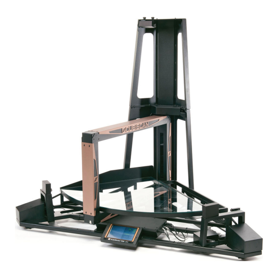
Chapter 1 Product Description The CubiScan 125 is a small static cubing system that uses a combi- nation of sensing technologies to measure and weigh irregu- larly-shaped parts and components as well as boxed items. Small parts and non-cuboidal items are measured with great precision using infrared sensing technology, while larger boxed items are measured with ultrasonic sensors. -
Page 12: Specifications
Specifications Product Description Figure 1 CubiScan 125 Specifications Power Requirements 100 – 240 VAC, 50 – 60 Hz CubiScan 125... - Page 13 Measurement Increment: 0.1 in (2 mm) 0.05 in (1 mm) Measurement Time: < 3 seconds < 5 seconds Object Colors: All colors Opaque Weight Capacity: 0.005 to 50 lbs (0.002 to 25 kg) Weight Increment: 0.005 lbs (0.002 kg) CubiScan 125...
- Page 14 Minimum PC Specifications: Windows 7/XP/95/98/NT/2000, Pentium II processor, 20 megabytes of disk space, screen resolution setting of 800 X 600 Quantronix’ QBIT™ software can be used to interface with the CubiScan 125. Display: Integrated TFT LCD touchscreen displays L, W, H, weight, unit of measure, 2D and height profile, and diagnostic codes.
-
Page 15: Chapter 2 Setup
Chapter 2 Setup This chapter provides instructions for assembling and setting up the CubiScan 125. Perform the steps to set up the CubiScan 125 in the following order: • Unpack the CubiScan 125 (page 5) • Place the CubiScan 125 where you will be using it (page 8) •... -
Page 16: Figure 2 Cubiscan 125 In Crate
Figure 2 CubiScan 125 in Crate Examine the container and the CubiScan 125 carefully for any dam- age. If, after unpacking, you discover any damage to the CubiScan 125, contact the carrier immediately. Refer to Figure 3 and the list below it to identify the components. -
Page 17: Figure 3 Cubiscan 125 Components
Setup Unpacking Figure 3 CubiScan 125 Components A Base assembly B Top sensor support C Glass platform D Cable cover E AC power cord CubiScan 125... -
Page 18: Placement
If any of the components or accessories are missing or defective, contact Quantronix or your system integrator. Carefully remove the CubiScan 125 and its components from the crate, and place the CubiScan 125 on a solid, stable surface for assembly (see “Assembling the CubiScan 125” on page 9. Placement The CubiScan 125 is designed to be operated in a warehouse envi- ronment;... -
Page 19: Assembling The Cubiscan 125
CubiScan 125 when not in use. • If a computer is used, place it as close to the CubiScan 125 as possible. The operator needs to use the keyboard or mouse on the computer while cubing and weighing packages using the Cubi- Scan 125. -
Page 20: Figure 4 Cubiscan 125 Base Assembly On Optional Cart
Assembling the CubiScan 125 Setup Figure 4 CubiScan 125 Base Assembly on Optional Cart CubiScan 125... -
Page 21: Figure 5 Raised Screws At Top Of Assembled Cubiscan 125
125 base assembly, and retain them to attach the top sensor sup- port. Remove 4 raised screws. Figure 5 Raised Screws at Top of Assembled CubiScan 125 3. Set the top sensor support in position on top of the CubiScan 125 gate support, and line up the screw holes. CubiScan 125... -
Page 22: Figure 6 Top Sensor Support Attached
Assembling the CubiScan 125 Setup 4. Insert the screws you removed in step 1 through the holes and tighten them. Figure 6 Top Sensor Support Attached CubiScan 125... -
Page 23: Attaching The Height Sensor Cable
Setup Assembling the CubiScan 125 Attaching the Height Sensor Cable The height sensor cable (gray cable with an RJ-12 connector) is connected to the controller on the front of the base assembly and is routed and tied through the base and gate support. It is coiled at the top of the gate support for routing up the top sensor support. -
Page 24: Figure 8 Routing The Height Sensor Cable
Assembling the CubiScan 125 Setup 5. Route the height sensor cable from the top of the gate support up the side of the top sensor support as shown below. Figure 8 Routing the Height Sensor Cable 6. Place the supplied cable ties over the sensor cable and through the holes on either side and secure them to hold the sensor cable in place. -
Page 25: Figure 9 Attaching The Sensor Cable Cover
Setup Assembling the CubiScan 125 7. Place the sensor cable cover over the wire as shown below, aligning the screws on the side of the sensor cover with the slots in the top support. Slide the sensor cover into place, and tighten the screws. -
Page 26: Figure 10 Connecting The Height Sensor Cable
Assembling the CubiScan 125 Setup 8. Connect the RJ-12 connector on the sensor cable to the connec- tor on the top of the height sensor as shown below. Figure 10 Connecting the Height Sensor Cable CubiScan 125... -
Page 27: Removing The Shipping Material
Setup Assembling the CubiScan 125 Removing the Shipping Material 1. Remove the green foam shipping supports from the CubiScan 125 base. Figure 11 Foam Shipping Supports CubiScan 125... -
Page 28: Figure 12 Cable Tie Holding Measuring Gate
Assembling the CubiScan 125 Setup 2. Cut the cable tie holding the measuring gate in place, and remove the bubble wrap. Figure 12 Cable Tie Holding Measuring Gate CubiScan 125... -
Page 29: Placing The Glass Platform
Setup Assembling the CubiScan 125 Placing the Glass Platform Remove the glass cubing and weighing platform from the cardboard box that was in the shipping crate, and carefully place it on the plat- form frame, as shown below. Figure 13... -
Page 30: Connecting Power
Figure 14 Connecting Power 2. Route the AC power cord under the CubiScan 125 base so it cannot be crushed, bent, or pulled loose. 3. Connect the other end of the AC power cord to a standard power outlet. -
Page 31: Turning On The Cubiscan 125
1. Make sure there are no packages or other objects on the Cubi- Scan 125 platform. 2. Turn on the CubiScan 125 with the power switch on the left side of the controller box (see “You can also connect the CubiScan 125 directly to a computer through a 10/100Base-T Ethernet TCP/IP port via a standard Ethernet cable. -
Page 32: Connecting To A Computer (Optional)
Refer to “Cubing and Weighing Using the Touch Screen” on page 38 for information. ☞ If you are not going to connect the CubiScan 125 to a computer or network, proceed to page 32 for information on connecting power. Connecting to a Computer (Optional) To connect the CubiScan 125 to a computer, do the following. -
Page 33: Figure 15 Serial Cable And Usb Connectors
☞ You need to load a driver on your computer before connecting it to the USB port, and you must turn on the CubiScan 125 before con- necting the USB cable for the first time. Refer to “Installing and Configuring the USB Driver” on page 24 for more information. -
Page 34: Installing And Configuring The Usb Driver
UnZip the folder C:\Program Files\CubiScan125USB. 3. With the CubiScan 125 turned on, connect the USB cable to your computer’s USB port and to the USB port on the CubiScan 125. In the bottom right-hand corner of the monitor, a bubble appears indicating that new hardware has been found. - Page 35 Setup Connecting to a Computer or Network The “Found New Hardware Wizard” window appears. 4. Select , and click . The following win- No, not this time [Next] dow appears. CubiScan 125...
- Page 36 If you installed the driver in a dif- ferent location, you need to browse to that location. Then click [Next] The wizard searches for and begins installation of the driver. When it is finished, the following prompt appears. CubiScan 125...
- Page 37 Connecting to a Computer or Network 7. Select , and wait for the installation to fin- [Continue Anyway] ish. The following window appears indicating that the configu- ration was successful. 8. Click to complete this part of the installation. [Finish] CubiScan 125...
- Page 38 The previous steps installed a Windows driver for the USB port. The “Found New Hardware Wizard” window opens again to install the CubiScan 125-specific driver. 9. Repeat steps 4 through 9. Another bubble appears in the bottom right-hand corner of the monitor indicating that the new hardware is ready for use.
- Page 39 Setup Connecting to a Computer or Network 13. Click the tab. Hardware CubiScan 125...
-
Page 40: Connecting To A Network (Optional)
Locate the Ports COM port assigned to the CubiScan 125. This is the COM port you will use when setting up Qbit applications to communicate with the CubiScan 125. In this example, the CubiScan 125 was assigned to COM9. -
Page 41: Figure 16 Ethernet Connector
2. The CubiScan 125 controller is located just behind the touch screen at the front of the base. Connect one end of the Ethernet cable to the Ethernet connector on the back of the CubiScan 125 controller, as shown below. Push the connector in until it locks. -
Page 42: Installing Qbit (Optional)
Installing Qbit (Optional) Setup When it is turned on, the CubiScan 125 will recognize the cable connection and, if configured correctly, will respond to a connection request from the host. ☞ You can also connect the CubiScan 125 directly to a computer through a 10/100Base-T Ethernet TCP/IP port via a standard Ethernet cable. - Page 43 Has the AC power cord been connected correctly? (page 32) ❒ If you are using Qbit to operate the CubiScan 125, has the soft- ware been copied onto your computer's hard-disk drive? (Refer to the Qbit User Guide for information.) ❒...
- Page 44 Setup Checklist Setup Notes CubiScan 125...
-
Page 45: Chapter 3 Operation
Operation This chapter provides instructions for operating the CubiScan 125. ☞ The platform of the CubiScan 125 should be kept clean and free of objects that are not being measured. Before You Begin Follow the procedures below to turn on the CubiScan 125. The CubiScan 125 should be turned on before you start Qbit (if applica- ble). -
Page 46: Cubiscan 125 Touch Screen
CubiScan 125 Touch Screen You can use the CubiScan 125 touch screen (below) to configure and control the CubiScan 125 as well as display measurement results. Figure 17... -
Page 47: Touch Screen Care
Cubing and Weighing The CubiScan 125 can be used to measure cuboidal objects as small as 2.0 inches, as well as irregularly-shaped, opaque objects as small as .1 inch (refer to “Specifications” on page 2 for specifications and size limitations on both). -
Page 48: Cubing And Weighing Using Qbit
Cubing and Weighing Using the Touch Screen All controls and displays for the CubiScan 125 are shown on the touch screen at the front of the base. If a computer is not connected, you can use the touch screen to cube and weigh packages. Measure- ments and weight cannot be recorded;... -
Page 49: Cubing/Weighing Cuboidal Items
☞ If you have not already done so, remove the thin protective film that covers the CubiScan 125 touch screen. Peel it back from one of the corners using your fingernail, and then pull it off. These display the measured dimensions in inches (in) or centimeters (cm) as selected. -
Page 50: Figure 19 Measurement Display
☞ Do not lean on or touch the CubiScan 125 platform or the package while a package is being cubed and weighed. Any kind of contact with the platform during the measurement process can alter the weight or sensor reading. -
Page 51: Cubing/Weighing Irregular Items
Operation Cubing and Weighing Cubing/ The CubiScan 125 has a measuring gate that you move over an item Weighing to measure objects with odd shapes or irregular surfaces. The mea- suring gate can measure opaque objects as small as .1 inch (2 mm). -
Page 52: Figure 20 Measuring Gate
Cubing and Weighing Operation ☞ Do not lean on or touch the CubiScan 125 platform or the package while a package is being cubed and weighed. Any kind of contact with the platform during the measurement process can alter the weight or sensor reading. -
Page 53: Figure 21 Measuring Gate Display
If the indicator does not light, it means that the CubiScan 125 zero needs to be zeroed. To zero the CubiScan 125, make sure that the platform is free of all objects, then tap [Zero] CubiScan 125... -
Page 54: Zeroing The Cubiscan 125
Cubi- Scan 125 to operate properly. The CubiScan 125 tries to zero itself automatically every five seconds when it is not in the Measure mode. -
Page 55: Chapter 4 Configuration
For information on calibrating the CubiScan 125 sensor and scale, refer to Chapter 5 “Calibration”. If you have a computer connected to the CubiScan 125 with Qbit installed, you can use Qbit to set up the measurement and dimen- sional weight units, select the CubiScan 125 communications port, perform calibration, and other functions. -
Page 56: System Configuration
System Configuration Configuration System Configuration The following options can be used to configure your CubiScan 125. 1. Tap at the main screen. [Menu] Figure 22 Main Screen ☞ If you have set up a password previously in the system configura- tion, you need to enter the password to unlock the menu. -
Page 57: Figure 23 Menu
Configuration System Configuration The menu buttons are displayed. Figure 23 Menu 2. Tap to display the system settings. [Setup] Figure 24 System Settings, First Screen CubiScan 125... -
Page 58: Figure 25 System Settings, Second Screen
(in lb) International: inches, kilograms (in kg) Domestic: inches, kilograms (in kg) 2278 International: centimeters, pounds (cm lb) 2720 Domestic: centimeters, pounds (cm lb) 5000 International: centimeters, kilograms (cm kg) 6000 Domestic: centimeters, kilograms (cm kg) CubiScan 125... -
Page 59: Figure 26 System Settings, Third Screen
From this screen you can change whether or not to use the Ethernet port, the sensors, or the scale, or select a language. 5. Tap to go to the next screen. [Next] Figure 27 System Settings, Fourth Screen CubiScan 125... -
Page 60: Figure 28 System Settings, Fifth Screen
If you set up a password, it must be entered each time to access the touch screen menu. The location code is used to identify the CubiScan 125 in the communications data. If you have more than one CubiScan 125, you need to set up a unique location number for each one. -
Page 61: Figure 29 Menu
9. Tap to change the “N” to “Y” and save the configuration. 10. Power off and then power back on the CubiScan 125. The changes are not recognized by the system until it is powered off and back on. -
Page 62: Communications Configuration
Communications Configuration Configuration Communications Configuration The following options can be used to configure communications. 1. Tap at the main screen. [Menu] Figure 30 Main Screen CubiScan 125... -
Page 63: Figure 31 Menu
Configuration Communications Configuration The menu buttons are displayed. Figure 31 Menu 2. Tap to display the communication settings. [Com] Figure 32 Communication Settings, First Screen CubiScan 125... -
Page 64: Figure 33 Communication Settings, Serial
3. Tap if you are using a serial communications port. [Ser] Figure 33 Communication Settings, Serial From this screen you can change the baud rate, parity, data bits, and stop bits. Tap to exit the serial communications [Ser] screen. CubiScan 125... -
Page 65: Figure 34 Communications Settings, Ethernet
Communications Configuration 4. Tap if you are using the Ethernet port. [Eth] Figure 34 Communications Settings, Ethernet From this screen you can view the IP, subnet, and gateway addresses in use, and you can turn DHCP on or off. CubiScan 125... -
Page 66: Figure 35 Communications Settings, Ethernet Second Screen
Communications Configuration Configuration 5. Tap to go to the next Ethernet screen. [Next] Figure 35 Communications Settings, Ethernet Second Screen From this screen you can change the static IP, subnet, gateway addresses, and port value. CubiScan 125... -
Page 67: Figure 36 Communications Settings, Ethernet Third Screen
Configuration Communications Configuration 6. Tap to go to the next screen. [Next] Figure 36 Communications Settings, Ethernet Third Screen From this screen you can view the MAC Ethernet address. 7. Tap to exit the Ethernet communications screen. [Eth] CubiScan 125... -
Page 68: Figure 37 Menu
10. Tap to change the “N” to “Y” and save the configuration. 11. Power off and then power back on the CubiScan 125. The changes are not recognized by the system until it is powered off and back on. -
Page 69: Chapter 5 Calibration
Calibrate the CubiScan 125 if you have problems cubing and weighing after assembly and setup. • Calibrate the CubiScan 125 if it is subjected to any type of mechanical shock or collision with a heavy object. • Calibrate the CubiScan 125 as part of a regular maintenance schedule. -
Page 70: Calibrating The Touch Screen
Calibration • Official 50 pound test weight • 12" x 5" x 3.6" calibration cube, supplied with the CubiScan 125 (remove the wrapping from the calibration cube before use) ☞ The calibration cube should be kept clean and undamaged—you will need it each time you calibrate the CubiScan 125. -
Page 71: Figure 38 Main Screen
Calibration Calibrating the Touch Screen 1. Tap at the main screen. [Menu] Figure 38 Main Screen The menu buttons are displayed. Figure 39 Menu CubiScan 125... -
Page 72: Figure 40 Calibration Menu
Calibrating the Touch Screen Calibration 2. Tap . The calibration menu is displayed. [Cal] Figure 40 Calibration Menu 3. Tap . The touch screen calibration screen is displayed. [TS] Figure 41 Calibration CubiScan 125... -
Page 73: Calibrating The Sensors
Calibrating the Sensors You will need the 12" x 5" x 3.6" calibration cube, supplied with the CubiScan 125, to calibrate the sensors. Remove the wrapping from the calibration cube before using it. To calibrate the sensors using the touch screen, proceed as follows. -
Page 74: Figure 43 Touch Screen Menu
Calibrating the Sensors Calibration The menu buttons are displayed. Figure 43 Touch Screen Menu 2. Tap . The calibration menu is displayed. [Cal] Figure 44 Calibration Menu CubiScan 125... -
Page 75: Figure 45 First Sensor Calibration Screen
3. Tap . The sensor calibration screen is displayed. [Xdcr] Figure 45 First Sensor Calibration Screen 4. Make sure there is nothing on the CubiScan 125 platform, and . The following screen is displayed. [Next] Figure 46 Second Sensor Calibration Screen... -
Page 76: Figure 47 Third Sensor Calibration Screen
[Next] Figure 47 Third Sensor Calibration Screen 7. Turn the calibration cube so that the 12" side is against the right side panel (make certain it is touching both side panels), as shown above. CubiScan 125... -
Page 77: Calibrating The Scale
[Prev] Calibrating the Scale To calibrate the CubiScan 125 scale, you need an official test weight up to 50 pounds (25 kg) (it is recommended that you calibrate with the maximum weight). CubiScan 125... -
Page 78: Figure 49 Main Screen
Take the following steps to calibrate the CubiScan 125 scale. ☞ When calibrating the scale, the CubiScan 125 must be stable with no movement of the platform such as that caused by vibration or air movement. -
Page 79: Figure 50 Menu
Calibration Calibrating the Scale The menu buttons are displayed. Figure 50 Menu 2. Tap . The calibration menu is displayed. [Cal] Figure 51 Calibration Menu CubiScan 125... -
Page 80: Figure 52 First Scale Calibration Screen
Calibrating the Scale Calibration 3. Make sure the CubiScan 125 platform is clear of all objects. Tap . The following screen is displayed. [Scale] Figure 52 First Scale Calibration Screen 4. If the weight units displayed are correct for the test weight you are using, proceed to the next step. -
Page 81: Figure 53 Second Scale Calibration Screen
[Next] Figure 53 Second Scale Calibration Screen 7. Make sure the CubiScan 125 platform is clear of all objects and to continue. The following screen is displayed. [Next] Figure 54 Third Scale Calibration Screen... - Page 82 Calibrating the Scale Calibration 8. Place the test weight onto the center of the CubiScan 125 plat- form (exact positioning is not required). Allow the scale to com- pletely stabilize, and tap [Next] 9. Tap twice to return to the menu screen.
-
Page 83: Chapter 6 Maintenance
Maintenance This chapter provides information on the care and maintenance of the CubiScan 125. Routine maintenance and careful handling will help keep the CubiScan 125 in good operating condition and prevent service calls or repairs. Precautions The CubiScan 125 should not be subjected to extremes in tempera- ture or humidity, nor should it be subjected to excessive vibration. -
Page 84: Cleaning The Sensors
1. Turn off the power switch, and disconnect the power cord from the controller box. 2. Remove the glass platform from the CubiScan 125 base. It can simply be lifted out. 3. Place the platform in a safe location where it will not get stepped on or broken. -
Page 85: Figure 55 Controller Box
To remove the load cell connector, turn the screws to loosen the connector, and pull it straight out. • To remove the power connector, take hold of the connector close to the panel, and pull it straight out using even pressure. CubiScan 125... - Page 86 Allen wrench. The touch screen is in the center of the mounting plate, and the mounting plate is attached to the front of the CubiScan 125 base. 7. Verify that all cables have been removed from the controller box, then pull the box out from the front.
-
Page 87: Chapter 7 Troubleshooting
After installation, most problems are caused either by incorrect cabling or because the system setup is not correct. If you are having problems with the CubiScan 125, first verify that all cables attached to the controller box (serial communications cables, sensor cables, power cord, Ethernet cable, load cell cable) are fully seated and secure (locking rings, clips, or screws). -
Page 88: No Response When You Turn Power On
No Response When You Turn Power On Troubleshooting No Response When You Turn Power On If there is no response when you power on the CubiScan 125, do the following: 1. Verify that the AC power cord is pressed firmly into the power socket (on the left side of the controller box). -
Page 89: Computer Error Messages
TCP/IP communication? (Qbit software is used to configure the CubiScan 125.) 6. Is there a problem with the CubiScan 125? Perform the Status function in Qbit to check the status of the CubiScan 125. 7. Is there a problem with the computer or network? Refer to your computer manual for information on troubleshooting the com- puter, or contact your network administrator. - Page 90 Computer Error Messages Troubleshooting Notes CubiScan 125...
-
Page 91: Appendix A Communications Protocol
“CubiScan 125 Command Set” on page 83 lists the commands in the CubiScan 125 command set used for cubing and weighing and to set up the CubiScan 125 for cubing and weighing. “TCP/IP Com- munications Setup Command Set” on page 102 lists the commands used to set up the CubiScan 125 for TCP/IP communications with a network. -
Page 92: Ethernet (Tcp/Ip) Cable Pin Assignments
Parity None Data Bits Start Bits Stop Bits Ethernet (TCP/IP) Cable Pin Assignments The CubiScan 125 Ethernet port uses the 10/100Base-T TCP/IP communications protocol. The following table shows the Ethernet RJ-45 connector pin assignments. RJ-45 Connector Pin Assignments Signal Description... -
Page 93: Cubiscan 125 Command Set
CubiScan 125 Command Set CubiScan 125 Command Set This section describes the commands recognized by the CubiScan 125 to cube and weigh packages and to set up the CubiScan 125 for cubing and weighing (dimension units, factor toggle, calibration, zero, and so on). -
Page 94: Continuous Measure
CubiScan 125 Command Set Communications Protocol Continuous Measure This command toggles on or off a continuous measure mode. The readings transmitted are Length, Height, Width, and Weight. Both dimensions and counts are transmitted. Description Type Range ASCII Command Format Start of Text... - Page 95 Communications Protocol CubiScan 125 Command Set Description Type Range ASCII Comma Alpha Weight Identifier Alpha Weight Numeric 000.00-999.99* Comma Alpha Dim. Wgt. Identifier Alpha Dim. Weight Numeric 000.00-999.99* Comma Alpha Wgt./Dim.Wgt Unit Alpha (E/M) 45h or 4Dh Comma Alpha Factor Identifier...
-
Page 96: Dimension Calibration
This function is required when one of the sensors is replaced or moved, when a new controller is installed, or for routine calibration. This command causes the CubiScan 125 to reply with a dimension calibration code each time it is issued. This command must be issued FIVE times to complete sensor calibration. -
Page 97: Dimension Units
Communications Protocol CubiScan 125 Command Set Dimension Calibration Code Descriptions: DA01 Clear the CubiScan DA02 Place 12" Target facing LEFT DA03 Place 12" Target facing RIGHT DA04 Place 12" Target facing UP DA05 Dimension Calibration Complete Dimension Units This command is used to set the dimension units to either English (inches) or metric (centimeters) mode. -
Page 98: Factor Toggle
CubiScan 125 Command Set Communications Protocol Description Type Range ASCII Neg. Acknowledge Alpha End of Text Control (ETX) Carriage Return Control (CR) Line Feed Control (LF) Factor Toggle This command is used to set the dimensional factor to either domes- tic or international. -
Page 99: Location Id/City Code
(CR) Line Feed Control (LF) Location Id/City Code This command is used to set the CubiScan 125 location identifica- tion. This data is stored in permanent memory and need only be set once for each CubiScan 125. Description Type Range... -
Page 100: Measure
(CR) Line Feed Control (LF) Measure Receipt of this command causes the CubiScan 125 to measure and weigh the package using the ultrasound sensors. The CubiScan 125 immediately formats the data collected and transmits it to the host computer. Description... - Page 101 Communications Protocol CubiScan 125 Command Set Description Type Range ASCII Width Numeric 000.0-999.9* Comma Alpha Height Identifier Alpha Height Numeric 000.0-999.9* Dimension Unit Alpha in/cm Comma Alpha Weight Identifier Alpha Weight Numeric 000.00-999.99* Comma Alpha Dim. Wgt. Identifier Alpha Dim. Weight Numeric 000.00-999.99*...
-
Page 102: Gate Measure
Leading spaces (20h) will be used when the actual data does not fill the entire field. Gate Measure The CubiScan 125 will automatically send measurement data upon completion of a gate measurement. Description Type... - Page 103 Communications Protocol CubiScan 125 Command Set Description Type Range ASCII Comma Alpha Weight Identifier Alpha Weight Numeric 00.000 - 99.999* Comma Alpha Dim. Wgt. Identifier Alpha Dim. Weight Numeric 000.00-999.99* Wgt./Dim.Wgt Unit Alpha lb/kg Comma Alpha Factor Identifier Alpha Factor...
-
Page 104: Scale Calibration
This function is required when the load cell is replaced, when a new controller is installed, or for routine calibration. This command causes the CubiScan 125 to reply with a scale calibration code. This command must be issued THREE times to complete scale calibra- tion. -
Page 105: Test
SA03 Scale Calibration Complete Test This command causes the CubiScan 125 to reply with an error code. A response of TA00 means that the CubiScan 125 is ready and responding to transmissions from the host. If the host receives no... -
Page 106: Units
End of Text Control (ETX) Carriage Return Control (CR) Line Feed Control (LF) Units This command causes the CubiScan 125 to report its current modes of operation. Description Type Range ASCII Command Format Start of Text Control (STX) Values Command... -
Page 107: Values
Control (ETX) Carriage Return Control (CR) Line Feed Control (LF) Values This command causes the CubiScan 125 to report all of its internal parameters. This is useful for troubleshooting. Description Type Range ASCII Command Format Start of Text Control (STX) - Page 108 CubiScan 125 Command Set Communications Protocol Description Type Range ASCII Width DBW Numeric 00.0-99.9 Comma Alpha Height DBW Numeric 00.0-99.9 Comma Alpha Length CPI Numeric 0000-9999 Comma Alpha Width CPI Numeric 0000-9999 Comma Alpha Height CPI Numeric 0000-9999 Comma Alpha...
- Page 109 Communications Protocol CubiScan 125 Command Set Description Type Range ASCII Length Wait Time Numeric 000-999 Comma Alpha Width Wait Time Numeric 000-999 Comma Alpha Height Wait Time Numeric 000-999 Comma Alpha Model Number Alpha “50” / “100L” Comma Alpha 50=10,20,30...
-
Page 110: Weight Units
CubiScan 125 Command Set Communications Protocol Weight Units This command is used to set the weight units to either English (pounds) or metric (kilograms) mode. Description Type Range ASCII Command Format Start of Text Control (STX) Wgt. Unit Command Alpha... -
Page 111: Zero
Communications Protocol CubiScan 125 Command Set Zero This command should be issued periodically to force the CubiScan 125 to perform internal compensations to adjust to changes in tem- perature and humidity. This command should only be issued when the measuring field is free of packages! Never issue this command when a package is present in the measuring field. -
Page 112: Tcp/Ip Communications Setup Command Set
RS-232-C serial communications port using the following commands. Set Port This command is used to set the CubiScan 125 TCP port number. In TCP/IP networks, port numbers are used to distinguish between dif- ferent logical channels on the same network interface on the same computer. - Page 113 Carriage Return Control (CR) Line Feed Control (LF) Negative Acknowledge Format Start of Text Control (STX) Set Command Alpha Port Command Alpha Neg. Acknowledge Alpha End of Text Control (ETX) Carriage Return Control (CR) Line Feed Control (LF) CubiScan 125...
-
Page 114: Read Port
TCP/IP Communications Setup Command Set Communications Protocol Read Port This command is used to read the current TCP Port number setting from the CubiScan 125. Description Type Range ASCII Command Format Start of Text Control (STX) Set Command Alpha Port Command... -
Page 115: Set Ip Address
TCP/IP Communications Setup Command Set Set IP Address This command is used to set the CubiScan 125 IP address. The IP address, or Internet address, is usually expressed in “dot” notation; for example, “121.43.6.234.” The first three groups of numbers (e.g., 121.43.6) are usually specific to the network to which you are... -
Page 116: Read Ip Address
(ETX) Carriage Return Control (CR) Line Feed Control (LF) Read IP Address This command is used to read the current IP address setting from the CubiScan 125. Description Type Range ASCII Command Format Start of Text Control (STX) Set Command... -
Page 117: Set Subnet Mask
Control (LF) Set Subnet Mask This command is used to set the CubiScan 125 subnet mask. The subnet (sub-network) is a separate part of an organization’s network. A subnet address tells the network’s router where on the network to send incoming packets of information. Subnet masking allows the router to move packets more quickly. -
Page 118: Read Subnet Address
(ETX) Carriage Return Control (CR) Line Feed Control (LF) Read Subnet Address This command is used to read the current subnet mask setting from the CubiScan 125. Description Type Range ASCII Command Format Start of Text Control (STX) Set Command... -
Page 119: Set Gateway Address
Set Gateway Address This command is used to set the network gateway address on the CubiScan 125. It can be the address of a network server or router and is expressed in “dot” notation. Consult your network adminis- trator to obtain the network gateway address. - Page 120 Carriage Return Control (CR) Line Feed Control (LF) Negative Acknowledge Format Start of Text Control (STX) Set Command Alpha Gateway Address Command Alpha Neg. Acknowledge Alpha End of Text Control (ETX) Carriage Return Control (CR) Line Feed Control (LF) CubiScan 125...
-
Page 121: Read Gateway Address
Communications Protocol TCP/IP Communications Setup Command Set Read Gateway Address This command is used to read the current gateway address setting from the CubiScan 125. Description Type Range ASCII Command Format Start of Text Control (STX) Set Command Alpha Gateway Address Command... - Page 122 TCP/IP Communications Setup Command Set Communications Protocol Description Type Range ASCII Carriage Return Control (CR) Line Feed Control (LF) CubiScan 125...
- Page 123 12890 Plate, Glass 12648 USB Cable * 11493 Serial Communications Cable, 10 ft. * 10083 Cord, AC Power * 10273 Calibration Cube, 12" x 5" x 3.6", Black 13339 Encoder with Connector 13357 User Manual * recommended spares CubiScan 125...
- Page 124 Parts List Notes CubiScan 125...
Need help?
Do you have a question about the CubiScan 125 and is the answer not in the manual?
Questions and answers