Sign In
Upload
Manuals
Brands
Quantronix Manuals
Measuring Instruments
CubiScan 125
Quantronix CubiScan 125 Manuals
Manuals and User Guides for Quantronix CubiScan 125. We have
2
Quantronix CubiScan 125 manuals available for free PDF download: Operation And Technical Manual, Service Manual
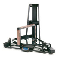
Quantronix CubiScan 125 Operation And Technical Manual (124 pages)
Brand:
Quantronix
| Category:
Measuring Instruments
| Size: 3 MB
Table of Contents
Table of Contents
5
Chapter 1 Product Description
11
Specifications
12
Figure 1 Cubiscan 125
12
Chapter 2 Setup
15
Unpacking
15
Figure 2 Cubiscan 125 in Crate
16
Figure 3 Cubiscan 125 Components
17
Placement
18
Assembling the Cubiscan 125
19
Figure 4 Cubiscan 125 Base Assembly on Optional Cart
20
Figure 5 Raised Screws at Top of Assembled Cubiscan 125
21
Figure 6 Top Sensor Support Attached
22
Attaching the Height Sensor Cable
23
Figure 7 Location of Height Sensor Cable
23
Figure 8 Routing the Height Sensor Cable
24
Figure 9 Attaching the Sensor Cable Cover
25
Figure 10 Connecting the Height Sensor Cable
26
Removing the Shipping Material
27
Figure 11 Foam Shipping Supports
27
Figure 12 Cable Tie Holding Measuring Gate
28
Placing the Glass Platform
29
Figure 13 Glass Cubing and Weighing Platform
29
Connecting Power
30
Figure 14 Connecting Power
30
Turning on the Cubiscan 125
31
Connecting to a Computer or Network
31
Connecting to a Computer (Optional)
32
Figure 15 Serial Cable and USB Connectors
33
Installing and Configuring the USB Driver
34
Connecting to a Network (Optional)
40
Figure 16 Ethernet Connector
41
Installing Qbit (Optional)
42
Setup Checklist
42
Chapter 3 Operation
45
Before You Begin
45
Cubiscan 125 Touch Screen
46
Figure 17 Cubiscan 125 Touch Screen
46
Touch Screen Care
47
Cubing and Weighing
47
Cubing and Weighing Using Qbit
48
Cubing and Weighing Using the Touch Screen
48
Figure 18 Measurement Display
48
Cubing/Weighing Cuboidal Items
49
Figure 19 Measurement Display
50
Cubing/Weighing Irregular Items
51
Figure 20 Measuring Gate
52
Figure 21 Measuring Gate Display
53
Zeroing the Cubiscan 125
54
Chapter 4 Configuration
55
System Configuration
56
Figure 22 Main Screen
56
Figure 23 Menu
57
Figure 24 System Settings, First Screen
57
Figure 25 System Settings, Second Screen
58
Figure 26 System Settings, Third Screen
59
Figure 27 System Settings, Fourth Screen
59
Figure 28 System Settings, Fifth Screen
60
Figure 29 Menu
61
Communications Configuration
62
Figure 30 Main Screen
62
Figure 31 Menu
63
Figure 32 Communication Settings, First Screen
63
Figure 33 Communication Settings, Serial
64
Figure 34 Communications Settings, Ethernet
65
Figure 35 Communications Settings, Ethernet Second Screen
66
Figure 36 Communications Settings, Ethernet Third Screen
67
Figure 37 Menu
68
Chapter 5 Calibration
69
Before You Begin
69
Calibrating the Touch Screen
70
Figure 38 Main Screen
71
Figure 39 Menu
71
Figure 40 Calibration Menu
72
Figure 41 Calibration
72
Calibrating the Sensors
73
Figure 42 Main Screen
73
Figure 43 Touch Screen Menu
74
Figure 44 Calibration Menu
74
Figure 45 First Sensor Calibration Screen
75
Figure 46 Second Sensor Calibration Screen
75
Figure 47 Third Sensor Calibration Screen
76
Calibrating the Scale
77
Figure 48 Fourth Sensor Calibration Screen
77
Figure 49 Main Screen
78
Figure 50 Menu
79
Figure 51 Calibration Menu
79
Figure 52 First Scale Calibration Screen
80
Figure 53 Second Scale Calibration Screen
81
Figure 54 Third Scale Calibration Screen
81
Chapter 6 Maintenance
83
Precautions
83
Cleaning the Sensors
84
Removing the Controller Box
84
Figure 55 Controller Box
85
Chapter 7 Troubleshooting
87
No Response When You Turn Power on
88
Readings Are Not Accurate
88
Computer Error Messages
89
Appendix A Communications Protocol
91
Serial (RS-232-C) Cable Pin Assignments
91
Ethernet (TCP/IP) Cable Pin Assignments
92
Cubiscan 125 Command Set
93
Continuous Measure
94
Dimension Calibration
96
Dimension Units
97
Factor Toggle
98
Location ID/City Code
99
Measure
100
Gate Measure
102
Scale Calibration
104
Test
105
Units
106
Values
107
Weight Units
110
Zero
111
TCP/IP Communications Setup Command Set
112
Set Port
112
Read Port
114
Set IP Address
115
Read IP Address
116
Set Subnet Mask
117
Read Subnet Address
118
Set Gateway Address
119
Read Gateway Address
121
Advertisement
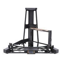
Quantronix CubiScan 125 Service Manual (95 pages)
Brand:
Quantronix
| Category:
Measuring Instruments
| Size: 7 MB
Table of Contents
Service Manual
1
Limited Warranty
2
Table of Contents
5
Chapter 1 Diagnostics
11
Figure 1 Cubiscan 125 Parts
11
Figure 1
11
Booting Process Errors
12
Failure in Initialization Process
12
Failure to Turn on
13
Gate Dimensional Errors
14
Inconsistent Measurement Readings
14
Incorrect Height Measurement
14
Item Exceeds Boundary
15
Black Lines in Measurements
16
Invalid Yellow Shapes in Measurement Results
16
Figure 2 Black Line in Measurement
16
Figure 3 Invalid Yellow Shapes in Measurement Results
17
Ultrasound Dimensional Errors
18
Inaccurate Measurement Readings
18
Gate Movement Errors
19
Gate Cursor Not Moving
19
Gate Cursor out of Box
19
Gate Speed Warning
20
Irregular Gate Movement
20
Return Gate to Home Error
20
Miscellaneous Errors
20
Frozen or Not Functioning
20
Ready Indicator Not Lighting
21
Touchscreen Is Not Functioning
21
Scale Errors
21
Dashes in Weight Field
21
Different Load Cells Report Different Weights
22
No Zero Indicator
23
Chapter 2 Scale Calibration
24
Figure 4 Main Screen
24
Figure 6 Calibration Menu
25
Figure 7 First Scale Calibration Screen
26
Figure 8 Second Scale Calibration Screen
27
Figure 9 Third Scale Calibration Screen
27
Chapter 3 Cleaning
28
Cleaning the Gate Filters
28
Cleaning the Glass Platform
28
Cleaning the Touchscreen
28
Cleaning the Ultrasound Sensors
28
Chapter 4 Updating the Firmware
29
Updating Firmware Via the SD Card
29
Figure 10 Controller Lid Screws
29
Figure 11 Jumper
29
Updating Firmware Via a Serial Connection
30
Figure 13 Controller Lid Screws
30
Figure 15 Jumper 2
31
Checking the Firmware Version
32
Chapter 5 Balancing the Load Cells
33
Figure 16 Load Cell Summing Box
33
Figure 18 Load Cell Wire Connections
34
Chapter 6 Part Replacement
35
Replacing a Fuse
35
Replacing the Display
36
Figure 19 Controller Box Screws
36
Replacing the Length or Width Ultrasound Sensor
37
Figure 20 Length/Width Sensor Screws
37
Replacing the Height Ultrasound Sensor
38
Figure 21 Height Sensor Screws
38
Replacing the Height Transmitter Board
39
Figure 22 Height Transmitter Gate Cover
39
Figure 23 Height Transmitter Board Assembly
39
Replacing the Height Receiver Board
40
Figure 24 Height Transmitter Board
40
Figure 25 Height Receiver Gate Cover
40
Replacing the Width Transmitter Board
41
Figure 27 Height Receiver Board Assembly
41
Figure 28 Width Transmitter Gate Cover
42
Figure 29 Width Transmitter Board Assembly
42
Figure 30 Width Transmitter Board
42
Replacing the Width Receiver Board
43
Figure 31 Encoder Cover Bolts
43
Replacing the Encoder
44
Figure 32 Width Receiver Gate Cover
44
Figure 33 Width Receiver Board
44
Figure 34 Encoder Cover Bolts
44
Figure 35 Encoder Cable Cover Screws
45
Figure 36 Encoder Screws
45
Figure 37 Encoder Set Screws
45
Replacing the Proximity Sensor
46
Figure 38 Proximity Sensor Screws
46
Replacing the Controller Box
47
Figure 39 Controller Box
47
Replacing the Inverter Board
48
Replacing the Motherboard
49
Figure 41 Controller Box Screws
49
Figure 42 Overview of Motherboard
50
Replacing the Power Supply
51
Replacing the Scale Card
52
Figure 45 Controller Box Screws
52
Replacing the Load Cell Summing Board
53
Figure 47 Overview of Motherboard
53
Figure 48 Load Cell Summing Box Screws
53
Figure 49 Inside Load Cell Summing Box
54
Figure 50 Load Cell Wiring Diagram
54
Replacing a Load Cell
55
Figure 51 Load Cell Summing Box Screws
55
Figure 52 Load Cell Bolts
55
Figure 53 Load Cell Nuts
55
Figure 54 Load Cell Wiring Diagram
56
Replacing Gate Cables
57
Figure 55 Front Platter Screws
57
Figure 56 Back Platter Screws
57
Figure 57 Encoder Cover Bolts
57
Figure 59 Encoder Set Screws
58
Figure 61 Gate Adjustment Bolts
58
Figure 63 Gate Board Labels
59
Figure 64 Height Transmitter Board Assembly
60
Chapter 7 Communication
62
Serial (RS-232) Communication
62
Figure 65 Controller Connections
62
Ethernet Communication
63
Ethernet Cable
63
Ethernet Cable with Ethernet to USB Adapter
63
USB Communication
64
Use COM Define
64
Appendix A Communication Protocol
66
Serial (RS-232-C) Cable Pin Assignments
67
Ethernet (TCP/IP) Cable Pin Assignments
67
USB Port Cable Pin Assignments
68
Figure 67 Parts List
95
Advertisement
Related Products
Quantronix CubiScan 110
Quantronix CUBISCAN 1200-AKL
Quantronix CUBISCAN 200 SQ
Quantronix CubiScan 110-T
Quantronix Cubiscan 110-XT
Quantronix CUBISCAN 25
Quantronix CUBISCAN 325
Quantronix Categories
Measuring Instruments
Accessories
Packaging equipment
Industrial Equipment
More Quantronix Manuals
Login
Sign In
OR
Sign in with Facebook
Sign in with Google
Upload manual
Upload from disk
Upload from URL