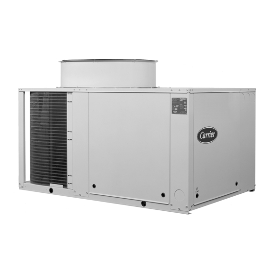
Summary of Contents for Carrier 38AJ 008
- Page 1 38AJ 008-074 (R-22) 38AZ 008-074 (R-407C) Air-Cooled Condensing Units 50 Hz Installation, Operation and Maintenance Instructions QUALITY ASSURANCE SYSTEM...
-
Page 2: Table Of Contents
CONTENTS Page Start-up checklist ..................................3 Dimensions and clearances ................................4 Physical and electrical data ................................. 6 Application data .................................... 7 Operating limits ....................................7 Installation ..................................... 7 Safety considerations ..................................7 Preliminary checks ..................................7 Moving and siting the unit ................................7 Refrigerant connections ................................ -
Page 3: Start-Up Checklist
START-UP CHECK LIST Start-up date: Equipment sold by: Contract No.: Installed by: Contract No.: Site address: Equipment type and serial numbers: Electrical data: Supply voltage: Ph. 2 Ph. 3 Nominal voltage: % network voltage: Current draw: Ph. 1 Ph. 2 Ph. -
Page 4: Dimensions And Clearances
Dimensions and clearances 38AJ/AZ 008-012 1220 1160 1200 1000 1000 1000 014-024 1720 1160 1112 1200 1000 1000 1000 030-036 2060 1370 1231 1000 1000 1000 1200 2450 1870 1912 2500 1200 1200 062-074 2900 2156 2060 2500 1200 1200 38AJ/AZ 008-012 38AJ/AZ 014-024 Do not obstruct... - Page 5 Dimensions and clearances 38AJ/AZ 062-074 38AJ/AZ 046 Do not obstruct Do not obstruct Floor mounting • For unit mounting holes, weight distribution and centre of gravity coordinates, refer to the dimensional drawings supplied with the unit. • These units are designed for outdoor installation. CAUTION: •...
-
Page 6: Physical And Electrical Data
5. The optional factory-installed circuit breaker is of type “a” (EN 60 204-1 § 5.3.2). • These Carrier units are designed and built to ensure conformance with local codes. The recommendations of European standard EN 60 204-1 (machine safety - electrical... -
Page 7: Application Data
Varifan III (option) unit is in its final position. Move the chiller using tubes or The Carrier Varifan III allows adjustment of the fan speed or of rollers, or lift it, using slings of the correct capacity. the three-phase motors (400 V-3 ph-50 Hz) at low outdoor temperatures. -
Page 8: Refrigerant Piping Diagram
In this case the unit wiring must be modified; release the holding charge (nitrogen). please refer to Carrier Service Bulletin No. SB 005- • Unsolder the plugs and prepare the pipes for connection. - Page 9 The refrigerant suction line should be insulated in accordance with the guidelines set forth in the Carrier System Design Manual (3rd part). Fig. 1 - 38AJ/AZ 008-036, single evaporator...
- Page 10 3. The lower section is always the first section to be activated and the last to be shut off. 4. Refer to the Carrier System Design Manual, Part 3, for more guidance on piping techniques. Fig. 6 - Suction line piping...
-
Page 11: Accessories
Swap any two of the three wires to correct the direction of which will invalidate the Carrier warranty. If the phase rotation, if necessary. imbalance exceeds 2% for voltage, contact your local... -
Page 12: Pressure Differential
Pressure differential (difference between cylinder The capacity control factory settings for 4-cylinder units are: load point and unloader points) 475 kPa gauge control setpoint (cylinder load point), 70 kPa differential, 405 kPa gauge cylinder unload point. Turn the adjusting screw counter-clockwise to its back stop position. -
Page 13: Servicing Refrigeration Components
SERVICING REFRIGERATION COMPONENTS Refrigerant guidelines Refrigeration installations must be inspected and maintained Any technician attending the machine for any purpose must be regularly and rigorously by specialists. Their activities must be a fully qualified refrigeration engineer. overseen and checked by properly trained people. To minimise discharge to the atmosphere, refrigerants and WARNING: Before doing any work on the machine ensure that lubricating oil must be transferred using methods which reduce... -
Page 14: Compressor Protection Circuit Board (Starterguard)
Recommended oil: NOTE: Damage resulting from failure to follow these R-22 semi-hermetic compressors: instruction is not covered by the product warranty.Compressor Mineral oil, Carrier specification No. PP 33-02 motor protection Suniso 3 GS (Sun Oil Co) Compressor protection devices Capella WF 32-150... -
Page 15: Fan Motor Replacement
For normal maintenance routines we recommend using 1 kg of • Withdraw the fan motor. the concentrated product, diluted to 10%, to treat a coil surface of 2 m . This process can either be carried out with a Installation is in the reverse order. Take care not to damage the TOTALINE applicator gun (part No. -
Page 16: Troubleshooting Chart
ENVIRONMENTAL MANAGEMENT Order No. 13811-76, May 1998. Supersedes order No.: 13811-76, September 1996 + 13883-76, April 1995. Manufactured by: Carrier SA, Montluel, France. Manufacturer reserves the right to change any product specifications without notice. Printed on Totally Chlorine-Free Paper. Printed in the Netherlands.


Need help?
Do you have a question about the 38AJ 008 and is the answer not in the manual?
Questions and answers