Carrier 38AUZ Series Installation, Start-Up And Service Instructions Manual
Hide thumbs
Also See for 38AUZ Series:
Table of Contents
Advertisement
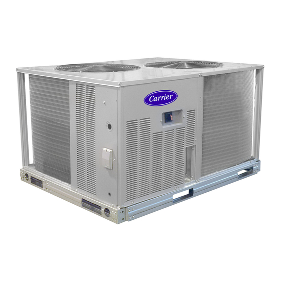
38AUZD/E
Air Cooled Condensing Units, 60 Hz
Single Circuit, 2---Stage with Digital Scroll Compressor
and Puron
(R ---410A) Refrigerant
R
Size 08
TABLE OF CONTENTS
. . . . . . . . . . . . . . . . . . . . . . . . . . .
. . . . . . . . . . . . . . . . . . . . . . . . . . . . . . . .
. . . . . . . . . . . . . . . . . . . . . . . . . . . . . . .
. . . . . . . . . . . . . . . . . . . . . . . . . . . . . . .
. . . . . . . . . . . . . . . . . . . . . . . . . . .
. . . . . . . . . . . . . . . . . . . . . . . . . . . . . .
. . . . . . . . . . . . . . . . . . . . . . . . . . .
. . . . . . . . . . . . . . . . . . . . . . . . . . . . . . . . . . .
. . . . . . . . . . . . . . . . . . . . . . . . . . .
. . . . . . . . . . . . . . . . . . . . . . . . . .
. . . . . . . . . . . . . . . . . . . . . . . . . . . . . . . . . . . .
Installation, Start---Up
and Service Instructions
. . . . . . . . . . . . . . . . . . . .
. . . . . . . . . . . . . . . . . . . . .
. . .
6- - 16
. . . . . . . . . . . . . . . . . .
. . . . . . . . .
. . . . . . . . . . .
. . . . . . . . . . . . . . . . .
. . . . . . . . .
. . . .
. . . . . . . . . . . . . . . . . . . .
. . . . . . . . .
. . .
. . . . . . . . . . . . . . . . . . . . .
16 - - 19
. . . . . . . . . . . . . . . . . . . . . .
. . . . . . . . . . . . . .
. . . . . . . . . . . . . . . . .
2
3
. . . . . . . . . . . . . . . . . . . . . . . . . . . . . . . .
6
6
6
6
6
6
7
8
10
10
16
16
. . . . . . . . . . . . . . . . . . . . . . . . . . . . . . . .
16
. . . . . . . . . . . . . . . . . . . . . . . . . . . . . . . . .
16
. . . . . . . . . . . . . . . . . . . . . . . . . . . . . . . .
16
16
APPENDIX A
17
20
20
APPENDIX B
20
20
APPENDIX C
20
20
. . . . . . . . . . . .
. . . . . . . . . . . . . . . . . . . . . . . .
. . . . . . . . . . . . . . . . . . . . . . . . .
. . . . . . . . . . . . . . . . . . . . . . . . . . . . . .
. . . . . . . . . . . . . . . . . . . . . . . . . . .
. . . . . . . . . . . . . . . . . . . . . . .
. . . . . . . . . . . . . . . . . .
. . . . . . . . . . . . . . . .
. . . . . . . . . . . . . . .
. . . . . . . . . . . . . . . . . . . . . . . .
. . . . . . . . . . . . . . . . . . . . . . . . . . . .
. . . . . . . . . . . . . . . . . . . . . . . . .
. . . . . . . . . . . . . . . . . . . . . . . . .
. . . . . . . . . . . . . . . . . . . . . . . .
. . . . . . . . . . . . . . . . . . . . .
-
. . . . . . . . . . . . . . . . . . . . . . . . .
. . . . . . . . . . . . . . . . . . . . . . . . . . .
. . . . . . . . . .
. . . . . . . . . . . . . . . . . . .
20
. . .
20
20
21 - - 27
21
21
21
21
21
21
22
24
24
24
24
24
24
26
27
27 - - 28
29
29
29
35 - - 36
Advertisement
Table of Contents

Subscribe to Our Youtube Channel
Related Manuals for Carrier 38AUZ Series


Summary of Contents for Carrier 38AUZ Series
-
Page 1: Table Of Contents
38AUZD/E Air Cooled Condensing Units, 60 Hz Single Circuit, 2---Stage with Digital Scroll Compressor and Puron (R ---410A) Refrigerant Size 08 Installation, Start---Up and Service Instructions TABLE OF CONTENTS ROUTINE SYSTEM MAINTENANCE ... . Quarterly Inspection (and 30 days after initial start) . -
Page 2: Safety Considerations
SAFETY CONSIDERATIONS WARNING Improper installation, adjustment, alteration, service, ELECTRICAL SHOCK HAZARD maintenance, or use can cause explosion, fire, electrical shock or other conditions which may cause personal Failure to follow this warning could cause in personal injury or property damage. Consult a qualified installer, injury or death. -
Page 3: Rated Indoor Airflow (Cfm)
10 11 12 13 14 15 16 17 18 Example 8 A U Z D 0 8 A 0 A 6 A 0 A 0 A 0 Model Type Packaging 38AU = Carrier Condensing Unit 0 = Standard ® Puron R-410A Refrigerant... - Page 4 C14298 STD. UNIT WT. CORNER A CORNER B CORNER C CORNER D CENTER OF GRAVITY UNIT HEIGHT UNIT lbs. lbs. lbs. lbs. lbs. 38AUZD/E08 [457] [610] [533] [1076] Fig. 2 - - 38AUZD/E08 Unit Dimensions...
- Page 5 Table 1 – Physical Data Table 2 – Physical Data 38AUZD/E08 — 60 Hz English 38AUZD/E08 — 60 Hz SI NOMINAL CAPACITY (tons) NOMINAL CAPACITY (kW) 26.4 OPERATING WEIGHTS (lb) OPERATING WEIGHTS (lb) Round Tube/Plate Fin Coil (Cu/Al) Round Tube/Plate Fin Coil (Cu/Al) ‡...
-
Page 6: Matching 38Auzd/E08 Model To Evaporator Coil
Matching 38AUZD/E08 Model to Evaporator bypass line. Relocate sections to minimize the length of interconnecting tubing. Coil The Model 38AUZD/E08 is a single-circuit, two- - stage DO NOT BURY REFRIGERATION LINES. unit design, requiring one set of refrigeration piping. Although unit is weatherproof, avoid locations that permit INSTALLATION water from higher level runoff and overhangs to fall onto the unit. -
Page 7: Step 5 - Determine Refrigerant Line Sizes
Also identify adjustments for refrigeration specialties. Refer to Part 3 of the Carrier System Design After the unit is in position, remove all shipping materials Manual for additional data and information on equivalent and top crating. lengths. Table 3 – 38AUZD/E08 Piping Recommendations... -
Page 8: Step 6 - Complete Refrigerant Piping Connections
Table 4 – Equivalent Lengths for Common Fittings (ft) suction speed riser (reduced tube size for vertical segment only) (see Fig. 4) or double suction riser arrangement (see Elbows Nominal Fig. 5) if the planned suction tube size does not provide Tube OD 90... - Page 9 Table 6 – Refrigerant Specialties Part Numbers LIQUID LINE LIQUID LINE LLSV SIGHT FILTER SIZE (in.) SOLENOID VALVE (LLSV) COIL GLASS DRIER EF680035 EF680037 KM680004 KH43LS085 EF680036 EF680037 KM680005 KH43LS087 Check 38AUZD/E08 Model with Evaporator Coil Evaporator Capacity Control Liquid Line Solenoid Valve: Many older unit designs included automatic Connections —...
-
Page 10: Step 7 - Install Accessories
For linear line lengths longer than 125 ft (38 m), contact Puron (R- - 410A) refrigerant systems operate at your local Carrier representative for system charge value. higher pressure than standard R- - 22 systems. Do not use R- - 22 service equipment or components on Puron Step 7 —... - Page 11 Field Power Supply — shaft and handle to the switch at this point. Discard the factory test leads (see Fig. 9). If equipped with optional Powered Convenience Outlet: The power source leads to the convenience outlet’s Units Without Disconnect Option transformer primary are not factory connected.
- Page 12 15) to determine the percent of voltage imbalance. Operation on improper line voltage or excessive phase imbalance constitutes abuse and may cause damage to electrical components. Such operation would invalidate any applicable Carrier warranty. Convenience Outlets — WARNING ELECTRICAL OPERATION HAZARD Failure to follow this warning could result in personal injury or death.
- Page 13 Non-powered type: This type requires the field The unit-powered convenience outlet has a 1000 VA rated installation of a general-purpose 125-volt 15-A circuit transformer. Maximum continuous current must not powered from a source elsewhere in the building. Observe exceed 8 Amps. national and local codes when selecting wire size, fuse or Test the GFCI receptacle by pressing the TEST button on breaker requirements and disconnect switch size and...
- Page 14 “230” and move it to the connection a PremierLink controller (available as a field-installed labelled “208”. See Fig. 16. accessory, for use on a Carrier Comfort Network or as a stand alone control). Thermostat — Install a Carrier-approved accessory thermostat according to installation instructions included with the accessory.
- Page 15 External Devices — Control transformer TRAN1 provides control power through terminal R to C on the field connection terminal strip TB for The 38AU control transformers provide 24- - v NEC Class 2 supply fan motor interlock. This source may also be used to power sources to energize external control devices.
-
Page 16: Step 9 - - Wind Baffles For Low Ambient Controls
Step 9 — Wind Baffles for Low Ambient Control Preliminary Charge — 38AUZE08 includes the factory installed 32LT Motormaster Before starting the unit, charge liquid refrigerant into the Low Ambient Control. high side of the system through the liquid service valve. The amount of refrigerant added must be at least 80% of the Units with 32LT Motormaster control require the addition operating charge listed in the Physical Data table (Tables 1... -
Page 17: Start Unit
Refer to Cooling Charging Chart, Fig. 19. For applications Temperature Protection will reset automatically before the with line lengths greater than 125 ft (38 m), contact Carrier motor protector resets, which may take up to 2 hours. representative. Vary refrigerant until the conditions of the chart are met. - Page 18 Using plotted operating point: Final Checks — Ensure that all safety controls are operating, control panel If plotted operating condition is - - Adjust charge by - - covers are on, and the service panels are in place. BELOW the curve REDUCE charge ABOVE the curve ADD charge...
- Page 19 C14294 Fig. 20 - - Typical 38AUZD/E08 Wiring Diagram - - 208/230V- - 3PH- - 60Hz Unit Shown...
-
Page 20: Operating Sequence
OPERATING SEQUENCE Cooling, Unit With Economizer — Refer to fan coil unit installation instructions and Base Unit Controls economizer accessory installation instructions operating sequences when system is equipped with — Indoor (Supply) Fan accessory economizer. The indoor fan contactor (IFC) is remotely located at the fan Heating —... -
Page 21: Service
SERVICE 3. Place terry cloth shop towel inside unit immediately un- der component(s) to be serviced and prevent lubricant Refrigeration System run-offs through the louvered openings in the base pan. 4. Perform required service. CAUTION 5. Remove and dispose of any oil contaminated material per local codes. -
Page 22: Comfort Alert Diagnostic Module
SEAT CORE (Part No. EC39EZ067) 1/2-20 UNF RH 0.596 45° 30° WASHER DEPRESSOR PER ARI 720 O-RING 1/2" HEX +.01/-.035 5/8” HEX FROM FACE OF BODY This surface provides a metal to metal seal when 7/16-20 UNF RH torqued into the seat. Appropriate handling is required to not scratch or dent the surface. - Page 23 Table 8 – LED Status Codes Status LED Status LED Description Status LED Troubleshooting Information Green “POWER” Module has power Supply voltage is present at module terminals Red “TRIP” Thermostat demand signal Y 1. Compressor protector is open LED On Solid is present, but the 2.
-
Page 24: Compressor Protection
Table 9 – CADM Troubleshooting Miswired Module Indication Recommended Troubleshooting Action Green LED is not on, Determine if both R and C module terminals are connected. Verify voltage in present at module’s R module does not power up and C terminals. NOTE: The CADM requires a constant nominal 24VAC power supply. - Page 25 Condenser Fans Service Valves C14295 Fig. 24 - - 38AUZD/E08 Exterior Outdoor Coil 32LT Sensor Typical Location High Flow Access Port C14296 Fig. 25 - - 38AUZD/E08 Interior...
-
Page 26: Routine Cleaning Of Round-Tube Plate Fin (Rtpf) Coils
NOTE: Proper eye protection such as safety glasses is cleaner is essential to extend the life of RTPF coils. This recommended during mixing and application. cleaner is available from Carrier Replacement parts division as part number P902-0301 for a one gallon container, and 1. Turn off unit power. -
Page 27: Fastener Torque Values
FASTENER TORQUE VALUES 9. Interior and exterior finned areas must be thoroughly cleaned. Table 10 – Torque Values 10. Finned surfaces should remain wet with cleaning Compressor mounting bolts 65--- 75 in–lbs solution for 10 minutes. (734–847 N–cm) 11. Ensure surfaces are not allowed to dry before rinsing. Condenser fan motor mounting bolts 20 2 in–lbs Reapply cleaner as needed to ensure 10-minute satur-... -
Page 28: Troubleshooting
TROUBLESHOOTING (cont) PROBLEM SOLUTION COMPRESSOR CYCLES ON LOW-PRESSURE SWITCH Indoor-Air Fan Running 1. Liquid line solenoid valve(s) fails to open. 1. Check liquid line solenoid valve(s) for proper operation. Replace if necessary. 2. Filter drier plugged. 2. Replace filter drier. 3. -
Page 29: Air Conditioner & Heat Pump With Puron R
APPENDIX A APPENDIX B Air Conditioner & Heat Pump with PURON Wiring Diagram List — Quick Reference Guide Electrical Diagram Unit Characteristics Number S Puron (R-410A) refrigerant operates at 50 percent to 208/230---3---60 38AU000026 70 percent higher pressures than R-22. Be sure that servicing equipment and replacement components are 460---3---60 38AU000027... - Page 30 Troubleshooting — Wind baffles are required to prevent wind cross currents from causing abnormally low condensing temperatures. OBSERVATION POSSIBLE REMEDY Use 20- - gauge sheet metal to fabricate wind baffles (see Fans won’t start All fans: Check power & wiring Fig.
- Page 31 C10800 Fig. 28 - - Wind Baffles...
- Page 32 Table 11 – Wind Baffle Dimension DIMENSIONS --- INCHES UNIT BAFFLE LEFT SIDE 38AUZDE 08 BACK RIGHT SIDE DIMENSIONS --- MM UNIT BAFFLE LEFT SIDE BACK 1016 1035 1054 38AUZE 08 RIGHT SIDE...
- Page 34 E 2019 Carrier Corporation Manufacturer reserves the right to discontinue, or change at any time, specifications or designs without notice and without incurring obligations. Catalog No. 04 ---53380040 ---01 Printed in U.S.A. Form 38AUZD ---E08 ---02SI 9 ---19 Replaces 38AUZD ---E08 ---01SI...
-
Page 35: Start-Up Checklist
START-UP CHECKLIST I. PRELIMINARY INFORMATION OUTDOOR: MODEL NO. SERIAL NO. INDOOR: AIRHANDLER MANUFACTURER MODEL NO. SERIAL NO. ADDITIONAL ACCESSORIES II. PRE-START-UP OUTDOOR UNIT IS THERE ANY SHIPPING DAMAGE? (Y/N) IF SO, WHERE: WILL THIS DAMAGE PREVENT UNIT START-UP? (Y/N) CHECK POWER SUPPLY. DOES IT AGREE WITH UNIT? (Y/N) HAS THE GROUND WIRE BEEN CONNECTED? (Y/N) - Page 36 INDOOR UNIT LEAVING-AIR WB TEMP COMPRESSOR AMPS (L1/L2/L3) NOTES: E 2019 Carrier Corporation Manufacturer reserves the right to discontinue, or change at any time, specifications or designs without notice and without incurring obligations. Catalog No. 04 ---53380040 ---01 Printed in U.S.A.
Need help?
Do you have a question about the 38AUZ Series and is the answer not in the manual?
Questions and answers