
Related Manuals for Amcrest IP5M-F1180EW-V2


Summary of Contents for Amcrest IP5M-F1180EW-V2
- Page 1 5MP V2 UltraHD Fisheye POE Camera User Manual Version 1.0.0 September 21 , 2021...
-
Page 2: Table Of Contents
Contents Welcome ..................................3 Important Security Warning ............................3 Important Safeguards and Warnings ..........................3 Features and Specifications ............................4 Overview ..................................4 Features ..................................4 Device Overview ................................5 Technical Specifications ..............................5 Connection & Installation .............................. 7 Connection Guide ................................7 Installation Guide ................................ -
Page 3: Welcome
USA: +1-713-893-8956 Canada: 437-888-0177 UK: 203-769-2757 Important Security Warning To keep your Amcrest camera secure and prevent unauthorized access, please make sure to follow the steps below: • Always make sure that your camera has the latest firmware as listed on www.amcrest.com/firmware... -
Page 4: Features And Specifications
Features and Specifications Overview Amcrest provides an excellent digital surveillance product that can be useful to a wide variety of users. This 5MP version 2 fisheye camera features the latest JS technology and updated chipset which allows the camera to be viewed in any web browser without the use of a plugin. -
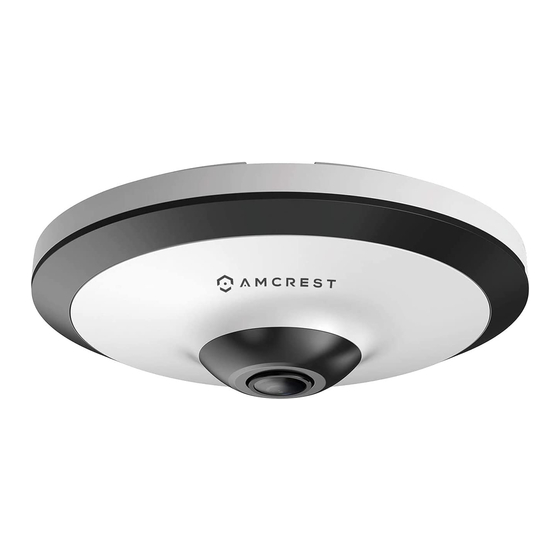
Page 5: Device Overview
Device Overview The image below shows the structure of the camera. The images below show the dimensions for the camera. The measurements are in millimeters (mm): Technical Specifications Model IP5M-F1180EW-V2 Camera Image Sensor 1/2.7”5Megapixel progressive CMOS Effective Pixels 2592 (H) × 1944 (V) - Page 6 Note: The DORI distance calculated based on sensor specification and lab test result 62676-4 which defines the criteria for Detect, Observe, Recognize, and Identify. Smart Event Heat Map Supported Intelligent Alerts IVS (Perimeter Protection) Tripwire; intrusion Support people counting in area, and displaying and outputting People Counting yearly/monthly/daily reports (matching devices are needed);...
-
Page 7: Connection & Installation
CGI; Milestone; Genetec; P2P User/Host 20 (Total Bandwidth: 64 MB) Storage Amcrest Cloud, FTP, NAS, MicroSD Card (Up to 256GB) Amcrest Surveillance Pro, Amcrest View Pro (iOS/Android), Amcrest Cloud, Management Software Amcrest Blue Iris, most mainstream web browsers including Google Chrome, Mozilla Firefox, Microsoft Edge, Safari, etc. - Page 8 Removing the Mounting Plate The mounting plate will be in the “open” state by default. Ensure that it stays “open” when installing the camera and adjust it to the close position after installation. Fixing the Mounting Plate When installing the mounting plate, use the included mounting template that was included with your camera. If you do not have the mounting template, line the mounting screws with the holes provided on the mounting plate.
-
Page 9: Microsd Card Installation Guide
Installing the Camera To install the camera onto a wall, follow the steps below: Using a drill, drill out the holes of the provided positioning map aligning the arrows on the mounting plate and positioning map. Insert the provided wall anchors into the holes. If the camera’s cables are being ran through the mounting surface, use a 1”... -
Page 10: Basic Wiring Overview
2. Open the hatch to expose the microSD card/factory reset button. 3. Place a microSD card into the provided microSD card slot, gold pins down, and press to secure. Note: To perform a factory reset on the camera, hold the WPS/Reset switch for 30 seconds allowing the device to reset. -
Page 11: Default Username And Password
1. Download and open the Amcrest Cloud app from the App Store or Play Store. Note: Connect your mobile device to the same network that your camera is on. 2. Register for an Amcrest Cloud account. To register click on Sign Up and fill out the form to complete registration. - Page 12 3. Tap on Add Camera 4. Give your camera a name (Ex. Garage, Living Room, Kitchen, etc.) and tap Next to continue. 6. If you are adding a new camera that does not have a 5. Scan the QR code on the back/side/bottom of set password the app will automatically detect that a the camera or manually enter the camera’s serial...
- Page 13 Download and install the Amcrest View Pro app for the App Store or Google Play Store. Open the app on your mobile device and allow the app to load.
- Page 14 3. Tap “Start”. 4. Tap “POE Camera”.
-
Page 15: Desktop Access Setup
The default username and password will be admin. Tap “Start Live View”. For more information about Amcrest View Pro and its functionalities visit amcrest.com/support Desktop Access Setup This camera features the latest in Java script technology which allows you to access your camera using a wide variety of web browsers including, Google Chrome, Firefox, Safari, or other mainstream web browsers using your PC or Mac. - Page 16 To access your camera from your computer you will need to first locate the camera’s IP address. To locate the camera’s IP address is it highly recommended to download our free Amcrest IP Config Tool software. The Amcrest Config Tool can be downloaded at the following web page: amcerest.com/downloads...
- Page 17 Enter in login details into the username and password fields and click login. Port Forwarding Remote Web Access Setup Port Forwarding is an alternative method to setting up remote access for Amcrest cameras. This method should only be used if the UPnP/DDNS Remote Access method did not work.
-
Page 18: Operation And Interface
For example, if the DDNS domain name is http://abc123456789.AmcrestDDNS.com and your HTTP Port is 33333, the URL would be http://abc123456789.AmcrestDDNS.com:33333 Enter in login details into the username and password fields and click login. If the process above is not working, please contact Amcrest Support via one of the following options: Visit http://amcrest.com/contact and use the email form. - Page 19 Section 5: This section allows the user to have quick access to Live view, Playback and Cloud Storage options. If you select Cloud Storage you will be directed to amcrestcloud.com to access or register an Amcrest Cloud account.
- Page 20 Section 6: This section allows the user to access Setup menus, Alarm, and log out the web user interface. For more information on the Setup menu, refer to section 5.4 Setup. Section 7: This section allows the user to view and adjust fisheye settings associated with the camera such as installation modes and play modes.
-
Page 21: Playback
Provides a six layered view of the live feed with one sub image. The sub image is used to control the corresponding layered views. Each view is depicted with different colors: Feed 1: Neon Green, Feed 2: Blue, Feed 3: Yellow, Feed 4: Purple, Feed 5: Turquoise, Feed 6: Red. Provides an eight layered image view of the live feed with one central control center. -
Page 22: Cloud Storage
PC. Cloud Storage The Cloud Storage tab allows the user quick access to the Amcrest Cloud website. At this website (amcrestcloud.com) users can register for new accounts as well as view or modify existing accounts. -
Page 23: Camera
There are 3 main sections to note in the Setup tab: Menu Bar: The menu bar is composed of menu sections, which when clicked display any menu items that fall under their category. Menu Items: These menu items each open a different menu that allows the user to change specific settings for the camera. - Page 24 • Profile: This dropdown box allows the user to select which profile to modify. The 3 options are Day, Night, and Normal. • Anti-Flicker: These radio buttons allow the user to select what type of anti-flicker technology should be used for the video feed.
- Page 25 • Regional Customized: Allows the user to select a specific region of the live feed to apply white balance settings. To reset to default settings, click the Reset Defaults button. To refresh the screen, click on Refresh. To save the settings, click the Save button.
-
Page 26: Video
To reset to default settings, click the Reset Defaults button. To refresh the screen, click on Refresh. To save the settings, click the Save button. Profile Management This option allows the user to set day and night profiles for the camera Below is an explanation for each of the fields on the Profile Management tab in the Configuration menu item: •... - Page 27 • Resolution: This dropdown box allows the user to set the resolution. The system supports various resolutions and they can be selected from this dropdown list. • Frame Rate (FPS): This dropdown box allows the user to select a frame rate. Frame rate settings are measured in frames per second (FPS) and can range from 1f/s to 25f/s in PAL mode and 1f/s to 30f/s in NTSC mode.
- Page 28 The menu on the left allows the user to select which overlay to modify. Privacy Masking, Channel Title, Time, and Text Overlay can all be modified in this menu. For Privacy Masking, the radio button enables or disables the feature. To set a privacy mask, click one of the boxes in the live view window, and position or resize it as needed.
- Page 29 • The Live Snapshot field allows the user to select where to save live snapshots to. Click the Browse button to select a different destination folder. • The Live Record field allows the user to select where to save live recordings to. Click the Browse button to select a different destination folder.
-
Page 30: Network
Enable: This checkbox allows the user to enable audio recording. Encode Mode: This dropdown box allows the user to select what audio format the audio should be recorded in. Sampling Frequency: This dropdown box allows the user to select a sampling frequency for the audio. The options are 8k and 16k. -
Page 31: Connection
QR code scanning feature cannot be used. • QR Code: This image is a Quick Response (QR) code. By scanning this image using the Amcrest View app, this camera can establish a connection with the app. - Page 32 Below is an explanation of the fields on the Connection settings tab: • Max Connections: This field allows the user to specify the maximum number of users that can be connected to the camera at the same time. The maximum number of users the camera can support at one time is 20. •...
- Page 33 For purposes of this guide, AmcrestDDNS will be used. AmcrestDDNS is a free DDNS service provided by Amcrest, and it must be renewed every year. A renewal reminder email will be sent to the email entered in the username field below.
- Page 34 Below is an explanation of fields on the SMTP (Email) settings screen: • SMTP Server: SMTP stands for Simple Mail Transfer Protocol. This field allows the user to enter the SMTP server used by the email service. • Port: This field allows the user to enter the port that corresponds to the selected SMTP server. •...
- Page 35 • Recipients: This field allows the user to enter the receiver email address. These email addresses are the ones that will receive any emails pertaining to alert and alarm emails sent by the camera. Up to 3 email addresses can be entered in this field.
-
Page 36: Event
For more information on how to setup HTTPS in the web user interface visit https://www.youtube.com/watch?v=gkjlaf-Iuso Event This menu section allows the user to change different settings for triggering events including setting up perimeter protection (IVS), people counting, heat map, and other useful features. Video Detection The video detection menu has two tabs: Motion Detect and Video Tamper. - Page 37 Click and drag to set motion detection for certain days of the week. Also, periods of motion detection can be set for each day and enabled using the period settings on the bottom half of the screen. There are a total of 6 periods that can be set.
- Page 38 • Record: This checkbox allows the user to enable the camera to record video when a motion detection alarm is triggered. • Record Delay: This field specifies in seconds how long the delay between alarm activation and recording should be. •...
- Page 39 ● Enable: This checkbox enables an audio detection alarm for the camera. Enable Intensity Change: This checkbox enables intensity change for the camera audio. o Sensitivity is the amount of change required to increase the audio detected by a percentage. The lower the sensitivity, the more audio variance is required to trigger an alarm. ●...
-
Page 40: Ivs
Setting an IVS Rule All IVS rules can only be set and/or modified using the web user interface. They cannot be set using the Amcrest View Pro app or any other platforms associated with your device. For more information on setting IVS rule, refer to the information below. - Page 41 No.: Provides the order in which the IVS rules will be displayed in the menu. Name: Allows the user to customize a name for their rule. Double click the name in the Rule column to modify. Rule Type: This dropdown menu allows the user to select an IVS rule type (Tripwire or Intrusion). Schedule: Allows the user to set a schedule in which the IVS rule will be triggered.
- Page 42 Below is a description of the features in this menu: No.: Provides the order in which the IVS rules will be displayed in the menu. Name: Allows the user to customize a name for their rule. Double click the name in the Rule column to modify. Rule Type: This dropdown menu allows the user to select an IVS rule type (Tripwire or Intrusion).
- Page 43 Draw Rule: This option allows the user to use their mouse to customize (draw) a rule/area on the screen. This will be the area or line in which an IVS rule will be triggered. Clear: This option is used to clear the drawn rule set on the live monitor screen. Target filter: Sets a maximum and minimum pixel size in which an event will be triggered.
- Page 44 Record: This checkbox allows the user to enable the camera to record video when the rule is triggered. Record Delay: This field specifies, in seconds, how long the delay between people counting events should be. The default is 10 seconds however this can be modified between 10~300 seconds. Relay Out: This checkbox allows the user to enable the camera to trigger a connected alarm (connected to the alarm port on the back of the camera) when a motion detection alarm is triggered.
- Page 45 Enable: Enable the Heat Map function Schedule: Set a period (if any) click Save to continue. To reset to default settings, click the Reset Defaults button. To refresh the page, click the Refresh button. To save the settings, click the Save button. Report Use the reports tab to view a report of the heat map.
- Page 46 Alarm This menu allows the user to set and schedule replay activated alarms. Below is a description of each field in this menu: • Enable: Allows the user to enable the relay activation function • Relay-In: Allows the user to set specific relayed alarms to the camera. •...
- Page 47 Below is an explanation of the fields on the SD Card settings tab: • Event Type: This dropdown box allows the user to select which SD card abnormality to set event triggers for. The 3 options are No SD Card, SD Card Error, and Capacity Warning. •...
-
Page 48: Storage
• Event Type: This dropdown box allows the user to select which Network abnormality to set event triggers for. The 2 options are Disconnection and IP Conflict. • Enable: This checkbox enables the Network abnormality trigger for the camera. • Record: This checkbox allows the user to enable the camera to record video when a network abnormality is detected. - Page 49 Schedule The schedule menu manages the recording schedule for the camera. This menu has 3 tabs: Record Schedule, Snapshot Schedule, and Holiday Schedule. Record Schedule This tab is where video recording settings are configured. Below is a screenshot of the Record Schedule settings screen: Below is an explanation of the fields on the Record Schedule settings tab: Record Type: These checkboxes allow the user to select which recording type they want to configure on the...
- Page 50 Snapshot Schedule This tab is where snapshot recording settings are configured. Below is a screenshot of the Snapshot Schedule settings screen: Below is an explanation of the fields on the Snapshot Schedule settings tab: • Record Type: These checkboxes allow the user to select which snapshot type they want to configure on the schedule.
- Page 51 • Record Type: These checkboxes allow the user to select which recording type they want to configure on the schedule. There are 2 types of recordings: Record: This checkbox is referring to video recording. Snapshot: This checkbox is referring to snapshot recording. •...
- Page 52 Below is an explanation of the fields on the SD Card settings tab: • Device Name: This column designates the name of the SD card that is currently in the camera. • Status: This column designates the status of the SD card. •...
- Page 53 Save button. Cloud Storage This menu redirects the user to the Amcrest Cloud web site. At this website (amcrestcloud.com) users can register for new accounts as well as view or modify existing accounts. For more information on Amcrest Cloud visit: amcrestcloud.com...
- Page 54 General This menu controls where general settings are configured. There are 2 tabs in this menu: General and Date & Time. General This tab is where the user can configure some basic camera settings. Below is a screenshot of the General tab: Below is an explanation of the fields on the General settings tab: •...
- Page 55 To reset to default settings, click the Reset Defaults button. To refresh the page, click the Refresh button. To save the settings, click the Save button. Manage Users This menu allows the user to change the user accounts on the camera. By default, the camera only has the admin account which has all rights/authorities.
- Page 56 This menu allows the user to upgrade the camera’s firmware. To upgrade the firmware for your camera, follow the steps provided below: • Go to amcrest.com/firmware • Search for the model number of your camera and download the latest firmware file. •...
- Page 57 Note: When upgrading the camera’s firmware, do not disconnect the internet or power from the camera. Information This menu section allows the user to view information about the camera for reference purposes. Version This screen allows the user to see various information about the camera’s software versions, as well as other information.
-
Page 58: Alarm
To use this menu, check the enable check box to enable remote log functionality. Enter the IP address, port number and device number of the device you would like to pull remote logs from. To save your settings, click Save. If you would like to refresh the screen to show applied settings, click Refresh. To set the screen back to its original default settings, click Reset Defaults. -
Page 59: Logout
The table on the right shows the alarm log and all the alarm instances that have occurred. The checkboxes allow the user to narrow down which alarms they want to see in the alarm log. Clicking the checkbox next to Prompt will cause the system to pop up a dialog box anytime an alarm is triggered. Clicking the checkbox next to Play Custom Alarm will use a custom alarm sound for the alarm prompt. - Page 60 The time and date settings may not be configured correctly. You can take the following steps to resolve the issue: • Log into your camera’s web user interface via a laptop or PC. • Navigate to Setup>>System>>General • Click on the Date & Time tab. •...
-
Page 61: Glossary Of Terms
• The alarm is not setup correctly. • The alarm cable is not connected correctly. • The alarm input signal is not correctly configured. • There are two loops connected to one alarm device. 11. Downloaded files cannot be played back. Below are a few possible reasons why this may be occurring: •... -
Page 62: Fcc Statement
• S/N – S/N stands for serial number. The S/N is unique to each camera and can be used to connect to different Amcrest apps and services to provide different methods of access to the camera. • Sensitivity – Sensitivity is the amount of change required to increase the motion detected by a percentage. The lower the sensitivity, the more movement is required to trigger an alarm. -
Page 63: Ic Warning Statement
RF exposure warning This equipment must be installed and operated in accordance with provided instructions and the antenna(s) used for this transmitter must be installed to provide a separation distance of at least 20 cm from all persons and must not be co-located or operating in conjunction with any other antenna or transmitter. - Page 64 To contact Amcrest support, please do one of the following: Visit http://amcrest.com/contact and use the email form Call Amcrest Support using one of the following numbers Toll Free US: (888) 212-7538 International Callers (Outside of US): +1-713-893-8956 USA: 713-893-8956 Canada: 437-888-0177...
Need help?
Do you have a question about the IP5M-F1180EW-V2 and is the answer not in the manual?
Questions and answers