
Related Manuals for Amcrest IP4M-1048EW


Summary of Contents for Amcrest IP4M-1048EW
- Page 1 Amcrest IP4M-1048EW / IP4M-1048EB 4MP POE AI Turret Camera User Manual Version 1.0.0 Revised December 19 , 2019...
-
Page 2: Table Of Contents
Destination ..........................75 System ............................78 Information ..........................83 Alarm ............................84 Logout ............................85 Remote Web Access Setup ......................85 Amcrest Cloud Desktop Setup ....................87 Web Access Setup (AmcrestView.com) ..................88 FAQs/Troubleshooting ......................89 Glossary of Terms........................90 FCC Statement ..........................92 IC Warning Statement .......................92 Appendix A: Toxic or Hazardous Materials or Elements .............93... -
Page 3: Welcome
To contact Amcrest support, please do one of the following: Visit http://amcrest.com/contacts Important Security Warning To keep your Amcrest camera secure and prevent unauthorized access, please make sure to follow the steps below: • Always make sure that your camera has the latest firmware as listed on www.amcrest.com/firmware... -
Page 4: Features And Specifications
Overview Amcrest provides an excellent digital surveillance product that can be useful to a wide variety of users. This camera connects uses an internet connection to allow the user to access all its features. It’s easy to use and can be viewed on a computer via the built-in web user interface or on your smartphone using the Amcrest View Pro app. -
Page 5: Device Overview
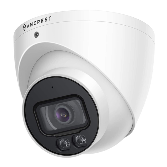
is imperative to make sure to mount the cameras properly and position them as efficiently as you can to the areas you wish to monitor. All positioning actions to the camera will have to be performed manually. Device Overview The image below shows the structure of the camera: The images below show the dimensions for the camera. -
Page 6: Connection Guide
Connection Guide The camera initially should be connected via the following method: Once connected to a PC or mobile device you will be able to configure the device to your network. For more information. Installation Guide To install the camera on a ceiling or wall, please reference the below diagram as well as the steps: Note: Prior to installation, please ensure that the installation environment can support at least 3x the weight of the camera and bracket. - Page 7 Figure 2-2 (b) Note: Due to specific hardware limitations within your camera it is important to note that these devices will not be able to automatically pan/tilt or pivot in either the app or via the web UI on a computer. For this reason, it is important to make sure to mount the cameras properly and manually position them as efficiently as you can to the areas you wish to monitor.
-
Page 8: Microsd Card Installation
How to Setup the Camera To make your experience with your Amcrest camera easy and simple, we've provided multiple ways to set up, view, and operate your camera depending on your needs. Please follow the instructions on this page to set up your... -
Page 9: App Setup
If you are setting up your camera for the first time, or you are setting up your camera for mobile viewing. Using the Amcrest Cloud app or Amcrest View app on your smartphone or tablet, you can view your camera live from anywhere, and access features such as taking snapshots, creating recordings, and more. - Page 10 Note: Connect your mobile device to the same network that your camera is on. 2. Register for an Amcrest Cloud account. To register click on Sign Up and fill out the form to complete registration. 3. Tap on Add Camera 4.
- Page 11 Make sure your camera is plugged into a power source and your Ethernet cable is connected from the camera to your router. • Make sure your camera and mobile device are on the same network during setup. Download and open the Amcrest View Pro app from the App Store or Play Store.
- Page 12 2. Open the app and tap on the + symbol in the middle 3. Tap on Add Device to add a new device to your app. of the screen to begin adding your PoE device. 4. Tap on PoE Camera Next, select a connection type.
- Page 13 9. Your camera is now set up and ready for use on the Amcrest View Pro app. Enter a password between 8 and 32 characters and confirm the password. Press OK to continue. For more information about Amcrest View Pro and its functionalities visit amcrest.com/support...
-
Page 14: Desktop Access Setup
To access your camera from your computer you will need to first locate the camera’s IP address. To locate the camera’s IP address is it highly recommended to download our free Amcrest IP Config Tool software. The Amcrest IP Config Tool can be downloaded at the following web page: amcerest.com/downloads... - Page 15 If this is the first-time logging into your device, you will be prompted to modify the password for your device. To modify the password, enter the new password you would like to use in the New Password field and confirm. The password used should be between 8 and 32 characters long with a combination of letters and numbers.
-
Page 16: Operation And Interface
By default, the interface opens on the Live tab. The live view tab allows the user to see a live video feed from the camera. The live view tab has five main sections: Section 1: These options allow the user quick access to the live view screen, playback, as well as to the Amcrest Cloud. -
Page 17: Playback
Section 6: This bar allows the user to change video settings for the live playback screen. See the below table for an explanation of the video settings: Button Function Name Function Description Image Adjustment This button opens the image adjustment toolbar, which allows the user to adjust brightness, contrast, saturation, and hue for the live feed’s picture. -
Page 18: Setup
Manual events. The “All” option will select all recording types in the interface. Cloud Storage The Cloud Storage tab allows the user quick access to the Amcrest Cloud website. At this website (amcrestcloud.com) users can register for new accounts as well as view or modify existing accounts. -
Page 19: Camera
There are 3 main sections to note in the Setup tab: 1. Menu Bar: The menu bar is composed of menu sections, which when clicked display any menu items that fall under their category. 2. Menu Items: These menu items each open a different menu that allows the user to change specific settings for the camera. - Page 20 Below is an explanation for each of the fields on the Configuration tab in the Configuration menu item: Picture • Profile: This dropdown box allows the user to select which profile to modify. The 3 options are Day, Night, and Normal.
- Page 21 Exposure This menu allows the user to select the exposure type for the video feed. Below is a screenshot of the exposure menu: • Profile: This dropdown box allows the user to select which profile to modify. The 3 options are Day, Night, and Normal.
- Page 22 • BLC: backlight compensation: Default will use the whole image to balance the lighting settings, and Customized will allow you to balance the lighting settings from the target area. • WDR: Wide Dynamic Range makes multiple scans of a scene to provide one balanced and unwashed image that is clear for the user.
- Page 23 To reset to default settings, click the Reset Defaults button. To refresh the screen, click on Refresh. To save the settings, click the Save button. Day & Night Day & Night profiles are used to determine when black and white mode is turned on in a dark environment. Below is a screenshot of this menu: •...
- Page 24 • B&W - Sets the picture to black and white, however when illumination is too dark it switches on IR mode. • Sensitivity: This option allows the user to change the Day/Night Sensitivity of the camera. The three options are Low, Middle, and High.
- Page 25 Profile: This dropdown box allows the user to select which profile to modify. The 3 options are Day, Night, and Normal. Mode: Allows the user to adjust defog settings. OFF: Allows the user to turn off defog mode, Manual: Allows the user to manually control defog settings, Auto: Allows the user to let the camera automatically detect defog settings.
- Page 26 Full Time means that the system sticks to one profile the entire time it is running. Schedule allows the user to dictate which times of the day are designated for the day profile and the night profile. Day/Night means that the system maintains one profile (Day or Night) for each mode set by the user.
- Page 27 Sub Stream is a lower quality stream that allows the feed to take up less resources and bandwidth when streaming. The Mainstream and the Sub Stream have the same fields. Sub Stream can be enabled by checking the box next to Enable. To reset to default settings, click the Reset Defaults button.
- Page 28 For Logo Overlay, the radio button enables or disabled the Amcrest logo from the live view screen. To reset to default settings, click the Reset Defaults button. To refresh the screen, click on Refresh. To save the settings, click the Save button.
- Page 29 • The Live Snapshot field allows the user to select where to save live snapshots to. Click the Browse button to select a different destination folder. • The Live Record field allows the user to select where to save live recordings to. Click the Browse button to select a different destination folder.
- Page 30 Below is an explanation for each of the fields on the Audio menu: • Enable: This checkbox allows the user to enable audio recording. • Encode Mode: This dropdown box allows the user to select what audio format the audio should be recorded in. •...
- Page 31 The P2P settings screen is where users can use a QR code to connect their smartphone or tablet to the camera. This feature needs to be enabled for use with the Amcrest View app, Amcrest Cloud, or AmcrestView.com. Below is a screenshot of the P2P settings tab:...
- Page 32 QR code scanning feature cannot be used. • QR Code: This image is a Quick Response (QR) code. By scanning this image using the Amcrest View app, this camera can establish a connection with the app.
- Page 33 For purposes of this guide, AmcrestDDNS will be used. AmcrestDDNS is a free DDNS service provided by Amcrest, and it must be renewed every year. A renewal reminder email will be sent to the email entered in the username field below.
- Page 34 Below is an explanation of fields on the IP Filter settings screen: • Trusted Sites: This checkbox allows the user to enable the IP Filter feature for trusted sites. • Add IP/MAC: This button opens a popup that allows the user to add IP or MAC addresses to the trusted site list. Note: When accessing the camera externally, please add the MAC address of the router on the PC end.
- Page 35 • Sender: This field allows the user to enter the sender email address. This email address will be the one that sends out all emails pertaining to the alerts and alarm emails sent by the camera. • Authentication: This dropdown box allows the user to select an encryption type. There are two types of email encryption protocols that are available.
-
Page 36: Event
The fourth column shows the Internal Port used by that service to establish communication from the router to the camera. To edit this, click the pencil button in the modify column for that line item. The fifth column shows the External Port used by that service to establish communication from the router to the internet. - Page 37 Video Detection The video detection menu has two tabs: Motion Detect and Video Tamper. Motion Detect This tab allows the user to modify motion detection settings. Below is a screenshot of the Motion Detect tab: Below is an explanation of the fields on the Motion Detect tab: Enable: This checkbox enables motion detection for the camera.
- Page 38 Click and drag to set motion detection for certain days of the week. Also, periods of motion detection can be set for each day and enabled using the period settings on the bottom half of the screen. There are a total of 6 periods that can be set.
- Page 39 Remember to click the save button on the motion detection settings screen, otherwise the motion detection zones will not go into effect. Clicking the cancel button to leave the motion detection zone and will not save the zone setup. • Record: This checkbox allows the user to enable the camera to record video when a motion detection alarm is triggered.
- Page 40 o Click and drag to set video tampering for certain days of the week. Also, periods of video tampering can be set for each day and enabled using the period settings on the bottom half of the screen. There are a total of 6 periods that can be set.
- Page 41 ● Enable: This checkbox enables an audio detection alarm for the camera. Enable Intensity Change: This checkbox enables intensity change for the camera audio. o Sensitivity is the amount of change required to increase the audio detected by a percentage. The lower the sensitivity, the more audio variance is required to trigger an alarm.
- Page 42 Click and drag to set audio tampering for certain days of the week. Also, periods of audio detection can be set for each day and enabled using the period settings on the bottom half of the screen. There are a total of 6 periods that can be set.
- Page 43 Setting an IVS Rule All IVS rules can only be set and/or modified using the web user interface. They can not be set using the Amcrest View Pro app or any other platforms associated with your device. For more information on setting IVS rule, refer to the information below.
- Page 44 Tripwire Tripwire allows the camera to trigger an event if an object, such as a human or vehicle, crosses the set tripwire line. Below is a screenshot of the Tripwire menu: Below is a description of the features in this menu: No.: Provides the order in which the IVS rules will be displayed in the menu.
- Page 45 Target filter: Sets a maximum and minimum size in which an event will be triggered. Draw Target: Allows the user to set a target area on the live monitor screen. An IVS event will not occur outside the target box. Clear: Clears the modified target area to draw the target area on the live monitoring screen.
- Page 46 Note: The target filtering and pixel counter can be used to refine the set rule however for optimal experience it is highly recommended to leave these settings as default To reset to default settings, click the Reset Defaults button. To refresh the page, click the Refresh button. To save the settings, click the Save button.
- Page 47 Record Delay: This field specifies, in seconds, how long the delay between IVS events should be. The default is 10 seconds however this can be modified between 10~300 seconds. Send Email: This checkbox allows the user to enable the camera to send an email when an IVS event is triggered. Snapshot: This checkbox allows a snapshot of the IVS event to be sent via Email when triggered.
- Page 48 To reset to default settings, click the Reset Defaults button. To refresh the page, click the Refresh button. To save the settings, click the Save button. Abandoned Object Abandoned Object allows the camera to trigger an event if an object is placed in a set area for a specified amount of time.
- Page 49 Below is a description of the features in this menu: No.: Provides the order in which the IVS rules will be displayed in the menu. Name: Allows the user to customize a name for their rule. Double click the name in the Rule column to modify. Schedule: Allows the user to set a schedule in which the IVS rule will be triggered.
- Page 50 To reset to default settings, click the Reset Defaults button. To refresh the page, click the Refresh button. To save the settings, click the Save button. Fast-Moving Fast-Moving allows the camera to trigger an event if an object, such as a human or vehicle, quickly moves in an area set by the user .
- Page 51 Below is a description of the features in this menu: No.: Provides the order in which the IVS rules will be displayed in the menu. Name: Allows the user to customize a name for their rule. Double click the name in the Rule column to modify. Schedule: Allows the user to set a schedule in which the IVS rule will be triggered.
- Page 52 To reset to default settings, click the Reset Defaults button. To refresh the page, click the Refresh button. To save the settings, click the Save button. Setting a Fast-Moving Rule 1. Select Fast-Moving from the Rule Type menu. Set a name for the rule by double clicking the mouse over the Name of the rule.
- Page 53 Below is a description of the features in this menu: No.: Provides the order in which the IVS rules will be displayed in the menu. Name: Allows the user to customize a name for their rule. Double click the name in the Rule column to modify. Schedule: Allows the user to set a schedule in which the IVS rule will be triggered.
- Page 54 Setting a Parking Detection Rule 1. Select Parking Detection from the Rule Type menu. Set a name for the rule by double clicking the mouse over the Name of the rule. 2. Click on Setup to set a schedule, set your periods (if any) and click Save to continue. 3.
- Page 55 Below is a description of the features in this menu: No.: Provides the order in which the IVS rules will be displayed in the menu. Name: Allows the user to customize a name for their rule. Double click the name in the Rule column to modify. Schedule: Allows the user to set a schedule in which the IVS rule will be triggered.
- Page 56 To reset to default settings, click the Reset Defaults button. To refresh the page, click the Refresh button. To save the settings, click the Save button. Setting a Crowd Gathering Rule 1. Select Crowd Gathering from the Rule Type menu. Set a name for the rule by double clicking the mouse on the Name of the rule.
- Page 57 Missing Object Missing Object allows the user to set a region around an object and if the object is moved or missing from the set region an alarm will be triggered. Below is a screenshot of the Missing Object menu: Below is a description of the features in this menu: No.: Provides the order in which the IVS rules will be displayed in the menu.
- Page 58 To reset to default settings, click the Reset Defaults button. To refresh the page, click the Refresh button. To save the settings, click the Save button. Setting a Missing Object Rule 1. Select Missing Object from the Rule Type menu. Set a name for the rule by double clicking the mouse over the Name of the rule.
- Page 59 Loitering Detection Loitering Detection is used to detect if a person or group are loitering in a specific area set by the user. Below is a screenshot of the Loitering Detection menu: Below is a description of the features in this menu: No.: Provides the order in which the IVS rules will be displayed in the menu.
- Page 60 To reset to default settings, click the Reset Defaults button. To refresh the page, click the Refresh button. To save the settings, click the Save button. Setting a Loitering Detection Rule 1. Select Loitering Detection from the Rule Type menu. Set a name for the rule by double clicking the mouse on the Name of the rule.
- Page 61 Below is a description of the features listed in this menu. Anti-Disturb Enable: These radio buttons allow the user to enable or disable anti-disturb. Anti-disturb is used to filter shaking leaves, water ripples, or any other disturbance that could affect IVS reporting. Sensitivity: This slider is used to adjust the sensitivity of the calibration settings used for IVS reporting.
- Page 62 Using Global Setup Global setup is a great tool to use to calibrate a detection area. This helps to increase the overall accuracy of the IVS rules being used as well as validate their It is highly recommended to use global access setup before setting up multiple IVS rules.
- Page 63 Note: The People Counting feature cannot be used simultaneously with IVS and/or Heat Map rules. These plans must be disabled in the Smart Plan menu and the people counting plan must be enabled to proceed. Below is a screenshot of the People Counting menu: Below is a description of the features listed in the People Counting menu: Enable: This checkbox is used to enable or disable the people counting feature.
- Page 64 Draw Rule: This option allows the user to customize the detection area on the live monitoring screen. This will be the area or line in which the feature will be triggered. Clear: This option is used to clear the detection area on the live monitor screen. A rectangular detection area is required for the camera to actively detect and count people.
- Page 65 Note: To disable this overlay, click on the IVS enable or disable icon ( ) located in the bottom portion of the live view screen. Report A people counting report can be generated that will graphically display the amount of people detected by the camera.
- Page 66 End Time: The date and time will end. Use the calendar and time boxes to enter an end time range. Flow Direction: These checkboxes can be used as filters for the report to show only certain criteria such as how many “Enters”, “Exits”, or “Display No.”...
- Page 67 The date and time range will be displayed on the top of the chart as well as a color-coded display and legend of the enters and exit statistics will be displayed as well. The left side of the chart will display the range of people that were reported.
- Page 68 Below is a description of the features listed in this menu: Enable: Enables the heat map function. This is enabled by default. Schedule: Allows the user to set a schedule in which the feature will be used. A Schedule must be set for the feature to function.
- Page 69 To reset to default settings, click the Reset Defaults button in the heat map menu. To refresh the page, click the Refresh button. To save the settings, click the Save button. Abnormality This menu allows the user to adjust abnormality event settings. This menu has 5 tabs: SD Card, Network, and Illegal Access, Voltage Detection, Security Exception.
- Page 70 Below is an explanation of the fields on the SD Card settings tab: • Event Type: This dropdown box allows the user to select which SD card abnormality to set event triggers for. The 3 options are No SD Card, SD Card Error, and Capacity Warning. •...
- Page 71 Illegal Access This tab allows the user to set the camera’s response to an Illegal Access related abnormality. Below is a screenshot of the Illegal Access tab screen: Below is an explanation of the fields on the Illegal Access settings tab: •...
-
Page 72: Storage
• Enable: This checkbox enables the voltage detection abnormality trigger for your camera. • Overlay: This checkbox allows an overlay to be triggered when the camera detects high amounts of input voltage. • Send Email: An email will be sent once the camera detects high levels of voltage input. To reset to default settings, click the Reset Defaults button. - Page 73 Below is an explanation of the fields on the Record Schedule settings tab: Record Type: These checkboxes allow the user to select which recording type they want to configure on the schedule. There are 3 types of recordings: General: General recording means that the camera captures all footage for the specified time period. General recording is represented by the color green.
- Page 74 Below is an explanation of the fields on the Snapshot Schedule settings tab: • Record Type: These checkboxes allow the user to select which snapshot type they want to configure on the schedule. There are 3 types of snapshots: General: General means that the camera will take snapshots during the specified time period. General recording is represented by the color green.
-
Page 75: Destination
Below is an explanation of the fields on the Holiday Schedule settings tab: • Record Type: These checkboxes allow the user to select which recording type they want to configure on the schedule. There are 2 types of recordings: Record: This checkbox is referring to video recording. Snapshot: This checkbox is referring to snapshot recording. - Page 76 • Record Type: These columns designate which recording type should be recorded to which event type. Check the box at the intersection of the record type and event type to designate where that recording should be sent to. To reset to default settings, click the Reset Defaults button. To refresh the page, click the Refresh button. To save the settings, click the Save button.
- Page 77 Below is an explanation of the fields on the FTP settings tab: • Enable: This checkbox allows the user to enable FTP uploading for the camera’s recorded media. • Server Address: This field allows the user to designate a DDNS address for the FTP server. •...
-
Page 78: System
Save button. Cloud Storage This menu redirects the user to the Amcrest Cloud web site. At this website (amcrestcloud.com) users can register for new accounts as well as view or modify existing accounts. For more information on Amcrest Cloud visit: amcrestcloud.com... - Page 79 General This menu controls where general settings are configured. There are 2 tabs in this menu: General and Date & Time. General This tab is where the user can configure some basic camera settings. Below is a screenshot of the General tab: Below is an explanation of the fields on the General settings tab: •...
- Page 80 Below is an explanation of the fields on the Date & Time settings tab: • Date Format: This dropdown box allows the user to change the date format used in the camera. • Time Format: This dropdown box allows the user to change the time format used in the camera. •...
- Page 81 • Description: This column shows a description of the account. • Modify: This column allows the user to modify the user account. • Delete: This column allows the user to delete a user account. Note: The admin account cannot be deleted. •...
- Page 82 This menu allows the user to upgrade the camera’s firmware. Below is a screenshot of the Upgrade screen: To upgrade the firmware for your camera, follow the steps provided below: • Go to amcrest.com/firmware-subscribe • Search for the model number of your camera and download the latest firmware file. •...
-
Page 83: Information
Information This menu section allows the user to view information about the camera for reference purposes. Version This screen allows the user to see various information about the camera’s software versions, as well as other information. Below is a screenshot of the camera’s version screen: On this screen, software version, web interface version, and ONVIF version are displayed. -
Page 84: Alarm
Remote Log The Remote Log menu allows users to retain log information from other remotely connected devices. Below is a screenshot of the Remote Log menu: Enable: Enables the remote log feature. IP Address: The IP address of the remote device Connection: The port number set for the remote device (1~65534) Device Number: The number of the device in the network segment. -
Page 85: Logout
Please refer to your router manufacturer’s documentation to learn how to enable uPnP on your router. Below is a step-by-step walkthrough that details how to setup Amcrest cameras for Remote Web Access using UPnP and DDNS: 1. - Page 86 7. Click the DDNS menu item on the left-hand menu, pick Amcrest DDNS from the drop down box, click the checkbox next to Server Type, and then click the Save button on the bottom right. 8. To set a custom DDNS name, fill out the Domain Name field and click Save.
-
Page 87: Amcrest Cloud Desktop Setup
Amcrest cameras can sync with Amcrest Cloud; a service that stores recorded video streams to enable long-term storage. Amcrest Cloud also allows the user to easily find and download recorded video for playback from any internet connected PC or Mac computer. -
Page 88: Web Access Setup (Amcrestview.com)
4. View your camera live or watch recorded clips using the menu button on the top of the page. You can also use the Amcrest Cloud app on iOS and Android to add more cameras, play recordings, and view your camera live, from anywhere. -
Page 89: Faqs/Troubleshooting
FAQs/Troubleshooting 1. The camera does not boot up properly. Below are a few possible reasons why this may be occurring: • The power input is not correct voltage. • The power cable connection is not secured correctly. • The firmware was upgraded incorrectly. 2. -
Page 90: Glossary Of Terms
• The client PC may have limited resources. • Multicast mode may be causing this issue. • A privacy mask or screensaver may be enabled. • The logged in user may not have enough rights to monitor real-time playback. • The camera’s local video output quality is not enough. - Page 91 • S/N – S/N stands for serial number. The S/N is unique to each camera and can be used to connect to different Amcrest apps and services to provide different methods of access to the camera. • Sensitivity – Sensitivity is the amount of change required to increase the motion detected by a percentage. The lower the sensitivity, the more movement is required to trigger an alarm.
-
Page 92: Fcc Statement
FCC Statement This device complies with Part 15 of the FCC Rules. Operation is subject to the following two conditions: (1) this device may not cause harmful interference, and (2) this device must accept any interference received, including interference that may cause undesired operation. The user’s manual or instruction manual for an intentional or unintentional radiator shall caution the user that changes, or modifications not expressly approved by the party responsible for compliance could void the user's authority to operate the equipment. -
Page 93: Appendix A: Toxic Or Hazardous Materials Or Elements
Appendix A: Toxic or Hazardous Materials or Elements Toxic or Hazardous Materials or Elements Component Name Cr VI PBDE Sheet ○ ○ ○ ○ ○ ○ Metal(Case) Plastic Parts ○ ○ ○ ○ ○ ○ (Panel) Circuit Board ○ ○ ○... - Page 94 All the designs and software here are subject to change without prior written notice. • All trademarks and registered trademarks mentioned are the properties of their respective owners. To contact Amcrest support, please do one of the following: Visit http://amcrest.com/contacts...
Need help?
Do you have a question about the IP4M-1048EW and is the answer not in the manual?
Questions and answers