Table of Contents
Advertisement
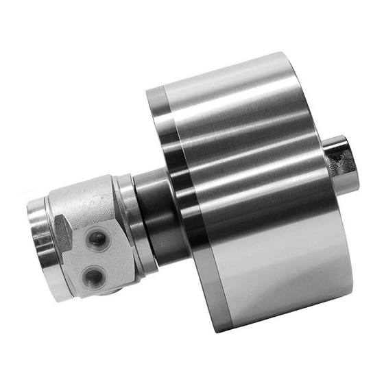
INSTRUCTION MANUAL
ROTARY HYDRAULIC CYLINDER
DANGER
・ This instruction manual is for production engineers and maintenance
personnel in charge of operation of this product. When a beginner
uses this product, receive instructions from experienced personnel,
the distributor or our company.
・ Before installing, operating or maintaining this equipment, carefully
read this manual and the safety labels attached to the equipment.
Failure to follow these instructions and safety precautions could result
in serious injury, death, or property damage.
・ Store this manual near equipment for future reference.
・ If any questions related to safety arise about this manual, please
confirm them with the distributor or our company.
Kitagawa Corporation
77-1,Motomachi,Fuchu -shi,Hiroshima,726 -8610,Japan
Y
type
CLOSED CENTER
TEL +81-(0)847 -40-0561
FAX +81-(0)847-45-8911
Version 1.12 (2021.07.07)
Original instructions
Advertisement
Table of Contents

Related Manuals for Kitagawa Y1530R


Summary of Contents for Kitagawa Y1530R
- Page 1 ・ Store this manual near equipment for future reference. ・ If any questions related to safety arise about this manual, please confirm them with the distributor or our company. Kitagawa Corporation 77-1,Motomachi,Fuchu -shi,Hiroshima,726 -8610,Japan TEL +81-(0)847 -40-0561 FAX +81-(0)847-45-8911...
- Page 2 MA0886RHG Preface This manual provides detailed information about how to safely and correctly use the cylinder (Y type) for a lathe. Before starting to use this cylinder, read this manual carefully and always follow the instructions and warnings in "Important Safety Precautions" and "Precautions for Use" at beginning of the manual.
- Page 3 The chuck and cylinder from Kitagawa Corporation should be used together. If you must use a part not made by Kitagawa, check with us or our distributor to be sure it is safe to do so. We will not be responsible for injury, death, damage or loss caused by use of a chuck or cylinder made by another company unless this use has been approved by Kitagawa or its distributor.
-
Page 4: Table Of Contents
MA0886RHG Table of Contents 1. Structural Drawing and Parts List ----------------------------------------------------------------------5 1-1. Type display 1-2. Structural drawing 1-3. Scope of product 1-4. Parts list Important Safety Precautions ----------------------------------------------------------10 3. Specifications ----------------------------------------------------------------------------------------------17 3-1. Specification table 4. Hydraulic Oil-------------------------------------------------------------------------------------------------19 5. Trial Operation----------------------------------------------------------------------------------------------21 6. - Page 5 MA0886RHG For Machine Tool Manufacturers (Chapter 9) 9. Attachment-------------------------------------------------------------------------------------------------- 9-1. Outline drawing of attachment 9-2. Production and attachment of cylinder adapter 9-3. Production and attachment of draw bar 9-4. Attachment of cylinder 9-5. Tightening torque of cylinder attaching bolt 10. About Hydraulic Circuit Design----------------------------------------------------------------------- 11.
-
Page 6: Type Display
MA0886RHG 1. Structural Drawing and Parts List 1-1. Type display Type display as shown below Example 5th digit and after that are not displayed for the standard cylinders. Abbreviated name of Y cylinders Nominal inside diameter of the cylinder Nominal piston stroke Cylinder with lock valve, relief valve RE Cylinder with lock valve, relief valve and proximity switch 5~7... -
Page 7: Structural Drawing
MA0886RHG 1-2. Structural drawing Y・R type Y・RE type Fig. 1 Note) Proximity switch is not included. Please prepare by yourself. -
Page 8: Scope Of Product
MA0886RHG 1-3. Scope of product This instruction manual is for the cylinder part. Fig. 2 ・ To prevent the work from flying, safe design, maintenance and erroneous action prevention of the hydraulic system to maintain the gripping force of the chuck is extremely important. -
Page 9: Parts List
MA0886RHG 1-4. Parts list Y・R type Fig. 3 Table 1 Part name Quantity Part name Quantity Lock valve Socket head cap screw 6,12or16 Relief valve Socket head cap screw Cylinder O-ring Rotary valve Sleeve O-ring Sleeve cover O-ring Piston O-ring Guide pin O-ring Oil seal... - Page 10 MA0886RHG Y・RE type Fig. 4 Table 2 Part name Quantity Part name Quantity Lock valve Socket head cap screw 6,12or16 Relief valve Socket head cap screw Cylinder O-ring Rotary valve O-ring Sleeve O-ring O-ring Piston O-ring Guide pin O-ring Set screw Oil seal Piston bar Oil seal...
-
Page 11: Important Safety Precautions
MA0886RHG Important Safety Precautions Important safety precautions are summarized below. Please read this section before first starting to use this product. Failure to follow the safety precautions below will result in DANGER serious injury or death. Turn off main power supply before attaching, inspecting or replacing cylinder, and before adding oil. - Page 12 MA0886RHG Important Safety Precautions Failure to follow the safety precautions below will result in ! DANGER serious injury or death. Do not allow the rotation speed of the chuck to exceed the maximum allowable speed limit. For All Users ・ If the rotation speed of the chuck exceeds the rotation speed limit, this is very dangerous as the chuck and work will fly out.
- Page 13 MA0886RHG Important Safety Precautions Failure to follow the safety precautions below will result in ! DANGER serious injury or death. Always tighten the bolts at the specified torque. (Refer to pages 37) For All Users ・ If the torque is insufficient or excessive, the bolt will break, which is dangerous as the cylinder or work will fly out.
- Page 14 MA0886RHG Important Safety Precautions Failure to follow the safety precautions below will result in DANGER serious injury or death. Use of a chuck and cylinder that cannot be used together safely may cause the cylinder to break at high pressure resulting in the chuck and work flying out.
- Page 15 MA0886RHG Important Safety Precautions Failure to follow the safety precautions below will result in ! DANGER serious injury or death. Provide sufficient strength for the draw bar (Refer to pages 32-33). Provide sufficient screw depth for the draw bar. Firmly tighten the draw bar. Apply adhesive to the thread part of the draw bar and screw it in at the specified torque.
- Page 16 MA0886RHG Important Safety Precautions Failure to follow the safety precautions below could result in WARNING serious injury or death. Do not modify the cylinder. For All Users ・ Doing so may damage the cylinder and cause oil leakage which could result in a fire. And if the hydraulic oil leaks, the gripping force of the chuck will lower and the work may fly out, which is dangerous.
- Page 17 ・ Dangerous since these lead to operation ・ Dangerous since it will be caught. mistakes and misjudgment. Do not attach the other than parts manufactured by Kitagawa Corporation to the cylinder. (Refer to pages 8-9, Fig.3-4) For Machine Tool Manufactures ・...
-
Page 18: Specifications
MA0886RHG 3. Specifications 3-1. Specifications table Y・R type (Cylinder with lock valve, relief valve) Table 3 Type Y0715R Y1020R Y1225R Y1530R Y2035R Piston stroke Push Piston surface area Pull Piston maximum Push 16.6 Pull 13.9 thrust force Maximum operating hydraulic pressure Maximum rotation speed 6000 6000... - Page 19 MA0886RHG Note 2) How to obtain the piston thrust force Operating Piston Operating - 0.25 Piston Maximum hydraulic pressure(MPa) × thrust force Thrust force Maximum operating - 0.25 (kN) (kN) hydraulic pressure(MPa) Note 3) When storing this product, the product should be subjected to the antirust treatment and stored in a place free from wetting, condensation, or freeze.
-
Page 20: Hydraulic Oil
MA0886RHG 4. Hydraulic Oil ○ To keep good operation of the cylinder, it is recommended to use hydraulic oil with a viscosity of 32cSt at 40℃. (ISO VG32 equivalent product) ○ Replace the hydraulic oil about once every six months. ○... - Page 21 MA0886RHG Safety information about hydraulic fluid and anti-rust oil Applicable range ・ Hydraulic fluid sealed in the product at the delivery. ・ Antirust agent applied to the product at the delivery. First aid measures After inhalation: Remove victim to fresh air. If symptoms persist, call a physician. After contact with skin: Wash off with mild cleaners and plenty of water.
-
Page 22: Trial Operation
MA0886RHG 5. Trial Operation Read safety precautions starting on page 10 before performing trial operation. (1) Check that the power voltage is at the specified voltage. (2) Set the pressure adjusting handle to the lowest state during trial operation, and check the turning direction of the pump in inching (shortly turn on and off the switch). - Page 23 MA0886RHG < Treatment when the cylinder cannot be operated > ○ Regardless of trial operation or normal operation, when the cylinder cannot be operated, try the operations specified below. 1. When the lathe spindle is rotating, stop rotation. 2. Turn the pressure adjusting handle of the pressure regulation valve for the chuck setting pressure (cylinder setting hydraulic pressure) at the hydraulic unit part, and raise the chuck setting pressure for about 0.5 MPa and repeat switching over the operation selecting switch of the cylinder to check the operation of the cylinder.
-
Page 24: Proximity Switch
MA0886RHG 6. Proximity switch 6-1. Specification ○ Y-RE type cylinder can be installed two pieces proximity switches for checking electrically the piston operation of a cylinder or for the detection of chucking/unchucking of a workpiece. The proximity switch is not included, so please prepare it by yourself by referring to the specifications of the proximity switch below. -
Page 25: Adjusting The Position Of A Proximity Switch
MA0886RHG 6-2. Adjusting the position of a proximity switch Read following instruction when you adjust the proximity switch. (Fig.7) ① Loosen the machine screw [31], then remove the cover [14]. ② Loosen the socket head cap screw [20] that fix the adjusting plate [15]. ③... -
Page 26: Maintenance And Inspection
MA0886RHG 7. Maintenance and Inspection 7-1. Maintenance and inspection of the cylinder If any malfunction occurs, return cylinder to our company for repair. If it is disassembled and reassembled at a place other than our company, it may not function correctly as well as cause precision failure. -
Page 27: Malfunction And Countermeasures
MA0886RHG 8. Malfunction and Countermeasures 8-1. In the case of malfunction Check the points specified below again and take measures. Table 8 Defective Measures Check that the hydraulic pressure is operating by the motion of the flexible hose, etc. Piston Operation Check that there are no mistakes in piping. -
Page 28: Where To Contact In The Case Of Malfunction
MA0886RHG ・ If the chuck failed due to a seizure or breakage, remove the chuck from the machine, following the disassembly steps in the chuck instruction manual, and then remove the cylinder by the reverse steps of "9. Attachment" after page 28. -
Page 29: For Machine Tool Manufacturers (Chapter 9)
MA0886RHG For Machine Tool Manufacturers Following pages are described for machine tool manufacturers (personnel who attach a cylinder to a machine). Please read following instruction carefully when you attach or detach a cylinder to machine, and please sufficiently understand and follow the instructions for safe operation. - Page 30 MA0886RHG ・ Attach the manual switching valve at a position where it is easy to operate for the attaching equipment. ・ Install the hydraulic unit at a position where the drain hose is not kinked and the needle of the pressure gauge is easily read. ・...
-
Page 31: Production And Attachment Of Cylinder Adapter
MA0886RHG 9-2. Production and attachment of cylinder adapter ・ Attach with the surface run-out of the cylinder adapter and the run-out of the spigot joint at 0.005 mm or less. (Fig. 10) Large run-out causes vibration and shortens the life of the cylinder significantly. ○... - Page 32 MA0886RHG Table 9 (Unit: mm) Socket head φA (F7) φB φC Type D (MAX) cap screw Y0715R 6-M6 Y0715RE01C Y1020R 6-M10 Y1020RE47 Y1225R 6-M12 Y1225RE47 Y1530R 12-M12 Y1530RE47 Y2035R 12-M16 Y2035RE47...
-
Page 33: Production And Attachment Of Draw Bar
MA0886RHG 9-3. Production and attachment of draw bar ○ Determine the length of the draw bar as shown below. ○ When screwing the draw bar into the piston, screw in a state that the piston comes inside. ・ Sufficiently degrease and apply adhesive on the thread part of the piston and the thread part of the draw bar, and then screw in and tighten. - Page 34 MA0886RHG The dimension L in Fig. 11 is determined from the distance A between the cylinder adapter and the back plate. Example) In the case of N-08, Y1225R, the cylinder adapter and back plate distance A = 800, The total length of the draw bar is to be L = A - 162 = 800 - 162 = 638. At the time of the screw process of the dimension C, the precision is to be JIS 6H and 6h, 6g matching the screw of the piston of the cylinder.
-
Page 35: Attachment Of Cylinder
MA0886RHG 9-4. Attachment of cylinder ・ When removing/installing the cylinder, use a lifting belt and perform as follows. (Fig.13) 1. To lift up the cylinder, engage a lifting belt with the draw bar and lift up the cylinder while supporting it. 2. - Page 36 MA0886RHG ・ To prevent the sleeve of the cylinder from rotating, provide a support by utilizing the screw of the sleeve. ・ After attaching the support to the lathe, provide clearance between the protrusion and the support so that force is not applied to the sleeve. ○...
- Page 37 MA0886RHG Cylinder attachment Cylinder adapter Fig. 15 Table 11 (Unit mm) Type Y0715R or equivalent 0.010 0.030 Y1020R or equivalent 0.010 0.030 Y1225R or equivalent 0.010 0.030 Y1530R or equivalent 0.010 0.030 Y2035R or equivalent 0.010 0.030 To obtain the above specified value of run-out, make the surface run-out of the cylinder adapter as small as possible.
-
Page 38: Tightening Torque Of Cylinder Attaching Bolt
MA0886RHG 9-5. Tightening torque of the cylinder attaching bolt Follow the figure below for the screw-in depth of the attaching bolt. Fig. 16 Table 12 Y0715R Y1020R Y1225R Y1530R Y2035R Type Y0715RE01C Y1020RE47 Y1225RE47 Y1530RE47 Y2035RE47 Bolt size Screw depth ※... -
Page 39: About Hydraulic Circuit Design
MA0886RHG 10. About Hydraulic Circuit Design ○ Consider the hydraulic circuit design so that the operation is easy and no mistakes in operation occur. Attempt failsafe for the circuit so as not to cause any accidents even in the case of blackout. - Page 40 MA0886RHG ○ It is incorporated with a mechanism to stop damage when the hydraulic oil filled inside the cylinder has increased its pressure due to the volume change (relief valve). Pay attention to the points specified below for functional maintenance of lock valve and relief valve.
- Page 41 MA0886RHG <Installation> The hydraulic pressure supply ports are port A (cylinder pushing side) and port B (cylinder pulling side) in Fig.18. Though both ports A and B have two ports each, connect the pipes to one port respectively and plug the reminders. For the size of each port, see Table 14. Table 14 Y0715R Y1020R...
-
Page 42: Other Information
MA0886RHG 11. Other information 11-1. About standards and orders This product is based on the following standards or orders. ・ Machinery directive:2006/42/EC Annex I ・ EN ISO12100:2010 ・ EN1550:1997+A1:2008 11-2. Information about markings of product Fig.18 11-3.About disposal Ultimate disposal of this product should be handled according to all national laws and regulations. - Page 43 EC Machinery Directive 2006/42/EC Annex VII part B. Product : Cylinder Model : Y-RE series (Models Y0715RE, Y0720RE, Y0725RE, Y1020RE, Y1030RE Y1225RE, Y1530RE, Y1550RE, Y2035RE, Y2050RE) Serial number : See original declaration Manufacturer...
- Page 44 The products herein are controlled under Japanese Foreign Exchange and Foreign Trade Control Act. In the event of importing and/or exporting the products, you are obliged to consult KITAGAWA as well as your government for the related regulation prior to any transaction.
Need help?
Do you have a question about the Y1530R and is the answer not in the manual?
Questions and answers