
Related Manuals for ARCBRO Scout 2 Series


Summary of Contents for ARCBRO Scout 2 Series
- Page 1 Service Support Spirit Scout-Ⅱ SERIES CNC Plate Cutting Machine install Manual Operator Manual ARCBRO| Revision 2 | English Date of issue: August, 2019 WWW.ARCBRO.COM Unique Solution...
- Page 2 No parts of this manual may be reproduced, stored in a retrieval system, or transmitted, in any form or by any means, electronically, mechanically, by photocopy, recording or otherwise, without the prior written permission of ARCBRO Company. This User’s Manual is only available for Scout 2 CNC Portable Cutting Machine.
-
Page 3: Technical Support
Service Support Spirit Technical Support Thank you very much to choose ARCBRO product, our whole engineer department work for you since the day you receive machine. When you have any questions during assembling or operating, it is free to contact us by Call, Email, Online help 7x24 hours. -
Page 4: Table Of Contents
Step 1: Unpack the equipment box and remove all items ........12 Step 2: Install longitudinal rail and control unit ............ 13 Step 3: Install crossbeam ..................18 Step 4: Install the flame cutting section ............... 20 Step 5: Install the plasma cutting section ............22 WWW.ARCBRO.COM Unique Solution... -
Page 5: Technical Parameters
Max cutting thickness 80mm Oxyfuel cutting torch 80mm neck ( Can update to 120mm neck if necessary ) Mechanical Torch Height Controller Optional cutting nozzle 4 nozzles ( #1, #2, #3, #4 ) for Acetylene or Propane Accuracy ±0.5mm WWW.ARCBRO.COM Unique Solution... -
Page 6: Notes
Note 5: Clean dust regularly to keep the rail and rack clean for smooth movement. Note 6: Avoid damage for the LED display screen of CNC system. Note 7: Equipment use environment: Ambient temperature: -10℃—+50℃ Environment humidity: 90﹪RH below Storage temperature: -20℃—+65℃ Sea level elevation: An altitude of 1000 m below WWW.ARCBRO.COM Unique Solution... -
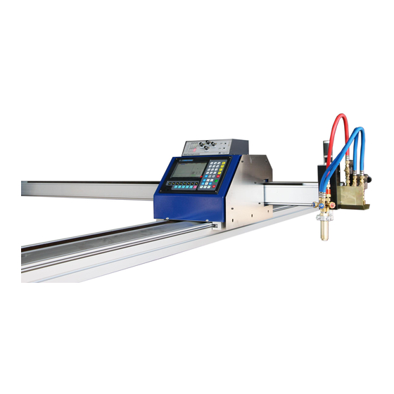
Page 7: Scout 2 Description
The Central Control Unit, containing the electronics commands ,the control panel, the display and keyboard, moves on these rails and hold the cross beam (X-Axis) supporting the cutting torch. WWW.ARCBRO.COM Unique Solution... -
Page 8: Safety
12. The gas supply has to be turn off in accordance with the following order in case of backfire or blockage of the nozzle. a) Turn off fuel valve b) Turn off pre-heating oxygen valve c) Turn off cutting oxygen valve 13. All valves must be turn off when Scout 2 is not in use. WWW.ARCBRO.COM Unique Solution... - Page 9 B. Put down, prevent hands and feet were clipped by machine; C. Be careful equipment dumping or tip over. 18. The machine should be each half a month for rack-and pinion with lubricating oil. 19: The machine put in place before the ground level, ensure WWW.ARCBRO.COM Unique Solution...
-
Page 10: Receive Your Package
Central Unit Electromagnetic value cable Electrical power cable Torch Lifter Holder Flame Torch Arc+/- &Arc start cable Torch mounting plate Fireproof plate Cross beam M8*45 T-bolt*4 M6X50 Cylinder head bolt*2 Tips of propane Aluminum Longitudinal rails Frame WWW.ARCBRO.COM Unique Solution... -
Page 11: Mechanical Assemble Steps
The whole machine weight is 120Kg, that needs 2 Part to finish assembling process. Please assemble according to below steps carefully. Any questions or help needed, please do not hesitate to contact ARCBRO after sale service engineer, we will provide help as soon as possible. -
Page 12: Step 1: Unpack The Equipment Box And Remove All Items
There are 15 parts in these two boxes, please check them one by one; if you have not bought software accessories, reduce one accordingly; Note: When unpacking the parts, do not scratch the equipment parts surface WWW.ARCBRO.COM Unique Solution... -
Page 13: Step 2: Install Longitudinal Rail And Control Unit
The machine is cut off. 1. Take out two sections of the longitudinal rails structure. Note: If the machine is 6 meters or there is a cut-off requirement, First the two bases need to be connect; WWW.ARCBRO.COM Unique Solution... - Page 14 3. Use bolts fix the Connecting plate to the rail base. Note: There are connecting plates on both sides of the base. 4. Use bolts fix the rack to the rail base. Note: There are connecting plates on both sides of the base. WWW.ARCBRO.COM Unique Solution...
- Page 15 1.Take the longitudinal rail out of the box and place it on the cutting table. 2.Remove the T-bolt from the accessories in the square box. T-bolt 3.Put the T-bolt into the gap under the longitudinal rail. Put T-bolts into the gaps at both ends of the longitudinal rail WWW.ARCBRO.COM Unique Solution...
- Page 16 Note: 1. When the T-bolt penetrates the longitudinal rail, it should be prevented from being crushed by the rail. 2. Tighten the T-bolt tightly with a nut to prevent vibrating during the operating of the machine and affect the cutting quality. WWW.ARCBRO.COM Unique Solution...
- Page 17 Side view of installation of the fireproof mounting bolts of the fire board and install board. the fireproof board. Note: When installing the fireproof board, use bolts to fix the fireproof board, and prevent your hands from being cut by the fireproof board. WWW.ARCBRO.COM Unique Solution...
-
Page 18: Step 3: Install Crossbeam
Service Support Spirit Step 3: Install crossbeam 1.Put the crossbeam into the control unit, the V-shaped wheel inside the control unit catches the optical axis above the crossbeam, and gently push the beam into the control box; WWW.ARCBRO.COM Unique Solution... - Page 19 Note: When passing plugs, insert in the hole inside the crossbeam at the inlet end of the crossbeam 3.Plug the aerial plug of the crossbeam control cable to the control aerial plug interface; Insert the crossbeam control cable into the control unit WWW.ARCBRO.COM Unique Solution...
-
Page 20: Step 4: Install The Flame Cutting Section
1.Remove the lifting body, flame torch placement plate, bolts and gaskets 2.Install flame torch Note: when installing the flame cutting torch, use a wrench to tighten the air pipe interface to prevent accidents caused by air leakage. WWW.ARCBRO.COM Unique Solution... - Page 21 2. Fix the lifting body with bolts Install the lifting body in front torch placement plate, bolts to fix the lifting body WWW.ARCBRO.COM Unique Solution...
-
Page 22: Step 5: Install The Plasma Cutting Section
3. Insert the beam plug in the lifting body and solenoid valve Connect the aviation plug to the lifting Connect the white plug to the lifting body body Step 5: Install the plasma cutting section 1.Insert the plasma torch cable into the circular hole inside the crossbeam WWW.ARCBRO.COM Unique Solution... - Page 23 3.Install the air pipe and cable in the plasma torch cable to the plasma power supply WWW.ARCBRO.COM Unique Solution...
- Page 24 4、Connect the arc starting signal line and arc voltage signal line to the control unit Plug starting signal cable into plasma signal plug socket. Insert the arc voltage signal cable into the reserved cable socket, ARC+ into the red cable, and ARC- into the blue cable WWW.ARCBRO.COM Unique Solution...
Need help?
Do you have a question about the Scout 2 Series and is the answer not in the manual?
Questions and answers