
Related Manuals for ARCBRO Stinger-PRO 5100 Series


Summary of Contents for ARCBRO Stinger-PRO 5100 Series
- Page 1 Service Support Spirit Stinger-PRO5100 SERIES High Definition Cutting Machine install Manual Operator Manual ARCBRO| Revision 2 | English Date of issue: August, 2020 WWW.ARCBRO.COM Unique Solution...
-
Page 2: Technical Support
Service Support Spirit Technical Support Thank you very much to choose ARCBRO product, our whole engineer department work for you since the day you receive machine. When you have any questions during assembling or operating, it is free to contact us by Call, Email, Online help 7x24 hours. - Page 3 No parts of this manual may be reproduced, stored in a retrieval system, or transmitted, in any form or by any means, electronically, mechanically, by photocopy, recording or otherwise, without the prior written permission of ARCBRO Company. This User’s Manual is only available for Stinger-PRO CNC Plate Cutting Machine.
-
Page 4: Table Of Contents
Step 3: Assemble each Side Board onto the frame leg ............18 Step 4: Assemble electrical box................... 19 Step 5: Assemble CNC System screen................20 Step 6: Adjust the flatness of the machine................21 Step 7: Plasma cutting part assemble................. 22 WWW.ARCBRO.COM Unique Solution... -
Page 5: Technical Parameters
English, Spanish, Russian, French, Japanese, Czech, Slovenia PLASMA CUTTING MODE Max cutting speed 15000mm/min Max cutting thickness Depends on plasma power source Plasma power source Support up to High definition plasma Arc voltage Auto Torch Height Controller Accuracy ±0.3mm WWW.ARCBRO.COM Unique Solution... -
Page 6: Notes
Note 5: Clean dust regularly to keep the rail and rack clean for smooth movement. Note 6: Avoid damage for the LED display screen of CNC system. Note 7: Equipment use environment: Ambient temperature: -10℃—+50℃ Environment humidity: 90﹪RH below Storage temperature: -20℃—+65℃ Sea level elevation: An altitude of 1000 m below WWW.ARCBRO.COM Unique Solution... -
Page 7: Safety
-2. The operator can’t load external program in internal storage of the machine in case of the virus. Only the special software recognized by ARCBRO can be applied. -3. During cutting period, when the floating voltage is too high, the operator should check the ground connection, neutral WWW.ARCBRO.COM... - Page 8 -8. Only trained personnel can be allowed to operate the equipment. Any maintenance should obey the user’s manual and before that the power should be cut off. Only experience technicist is allowed to change assemblies. WWW.ARCBRO.COM Unique Solution...
-
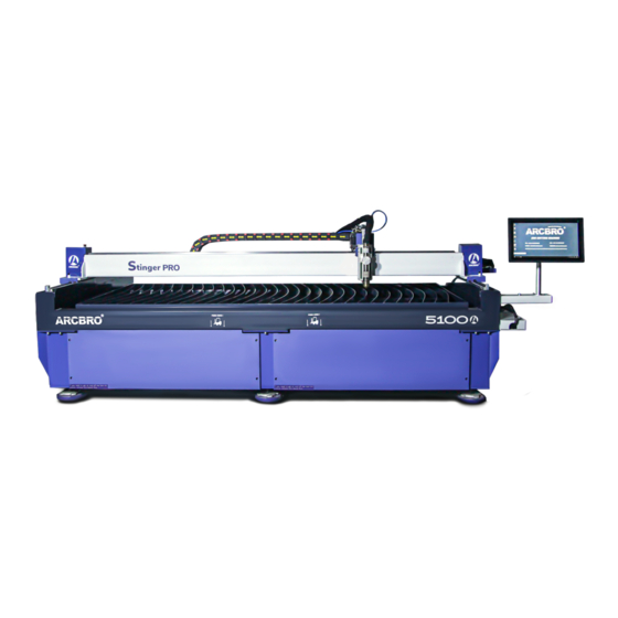
Page 9: Stinger-Pro Description
And it has been designed and built from the ground up by ARCBRO engineer team- ensuring a world class product with the quality and reliability you have come to expect. -
Page 10: Packing List
The Stinger-PRO transportation boxes contain: This accessory is standard configuration, if your machine is customized, the accessories are according to the order requirements. The bolts of the machine are fixed to the machine. Packing List: WWW.ARCBRO.COM Unique Solution... -
Page 11: Installation
This part describe how to install Stinger-PRO 1.5x3m portable CNC cutting machine step by step. Please assemble according to below steps carefully. Any questions or help needed, please do not hesitate to contact ARCBRO after sale service engineer, we will provide help as soon as possible. ... -
Page 12: Basic Assemble Steps
Step 3: Assemble each Side Board onto the frame leg. Step 4: Assemble electrical box. Step 5: Assemble CNC System screen. Step 6: Adjust the flatness of the machine. Step 7: Plasma cutting part assemble. WWW.ARCBRO.COM Unique Solution... -
Page 13: Step: Unpack The Equipment Box And Remove All Items
Step: Unpack the equipment box and remove all items Remove all the screws which are fixed the box, check and confirm all the spare parts be inside and well, and then move all the parts out safely. WWW.ARCBRO.COM Unique Solution... - Page 14 Service Support Spirit WWW.ARCBRO.COM Unique Solution...
-
Page 15: Step 1: Assemble The Legs Of The Gantry Frame
Forklift( Mind the drag chain and cables). 2. Install the leg to the frame. The support legs and the frame are marked with serial numbers, please install accordingly. Forklift lifting location WWW.ARCBRO.COM Unique Solution... - Page 16 Service Support Spirit Assemble Step: 3. Connect and fix all legs onto the Gantry Frame by screw. Note: Keep the machine stable. Frame assembled WWW.ARCBRO.COM Unique Solution...
-
Page 17: Step 2: Installation Of Dust Extraction Table
In order to install simply, an installation engineer is required to install the hopper at the bottom of the frame. Hopper Hopper 2--The two dust removal pipes of the hopper pass through the side board. Then connect to the dust collector. WWW.ARCBRO.COM Unique Solution... -
Page 18: Step 3: Assemble Each Side Board Onto The Frame Leg
Step 3: Assemble each Side Board onto the frame leg Fix each Side Board onto the frame leg by screws-4pcs. The Side Board and the frame are marked with serial numbers, please install accordingly. The Side Board assembled WWW.ARCBRO.COM Unique Solution... -
Page 19: Step 4: Assemble Electrical Box
1--Fix electrical box onto drag chain trough by screws; The electrical box Assemble Step: 1-- Fix electrical box onto drag chain trough by screws. NOTE: electric box is too heavy and requires two people to install it. The electrical box assembled WWW.ARCBRO.COM Unique Solution... -
Page 20: Step 5: Assemble Cnc System Screen
The motion controller Step 5: Assemble CNC System screen. 1-- Fix Screen support shelf onto frame by screws. 2-- Fix CNC System onto Screen support shelf by screws. CNC System screen assembled WWW.ARCBRO.COM Unique Solution... -
Page 21: Step 6: Adjust The Flatness Of The Machine
Adjust the flatness of the machine through the adjustment screw of the foot, to make sure: a- the 2 track on same horizontal level [The level precision request: ±0.5mm]; b- The overall flatness of the machine ≤ 1; The adjustment screw WWW.ARCBRO.COM Unique Solution... -
Page 22: Step 7: Plasma Cutting Part Assemble
Service Support Spirit Step 7: Plasma cutting part assemble. 1. Load the plasma torch to the holder. 2. Connected the plug to the IHS box. IHS wire Connection: Connect the IHS wire to the shield of the plasma torch. WWW.ARCBRO.COM Unique Solution... - Page 23 —DIV ARC+/- cable to Original Arc Voltage ports inside of the plasma power source. If HD plasma, -- Communication cable connected to the plasma. Note: Ref. your plasma power source handbook for recommended Torch Height for different thickness. WWW.ARCBRO.COM Unique Solution...
Need help?
Do you have a question about the Stinger-PRO 5100 Series and is the answer not in the manual?
Questions and answers