Table of Contents

Related Manuals for ARCBRO Stinger Series


Summary of Contents for ARCBRO Stinger Series
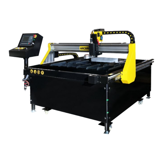
- Page 1 StinGEr SERIES CNC Plate Cutting Machine User’s Manual Reference: Revision: Date of issue: May, 22nd, 2017 Beijing ARCBRO LTD, Xinfang Industrial Park NO.218, ChaoYang District 100024, Beijing China Tel: +86 10 65798995 Fax: +86 10 65790867 http://www.ARCBRO.com...
- Page 2 There may be few differences between the pictures in this User’s Manual and the machine you re- ◆ ceived. Never hesitate to contact us for on-line technical service when you have any questions or you need ◆ help, and it's our pleasure to be there for help. Our E-mail is : support@arcbro.com...
-
Page 3: Technical Support
Technical Support Thank you very much for choosing ARCBRO products, our whole engineer team would love to work for you since the day you have received the machine. Whenever you have any questions during the process of assembling or operating, please feel free to contact us via Call, Email, or Online help 7x24. -
Page 4: Technical Parameter
Temperature Notes Note 1: Nesting software of ARCBRO Plate is not included in standard package. Note 2: The machine must be grounded reliably when it is working. (Connect the plate and the earth) Note 3: Clean dust regularly to keep the rail and rack clean for smooth movement. - Page 5 1.3. Programming and Nesting Using ARCBRO plate nesting software, you can edit and do the nesting process for your pattern de- signed by CAD, then generate a G-code cutting file in txt format. This txt cutting file can be recognized and carried out by our CNC system when you import it by a USB drive.Now, running Stinger , you can...
-
Page 6: Safety Information
2. The operator can’t load external program in internal stor- age of the machine in case of the virus. Only the special software recognized by ARCBRO can be applied. 3. During cutting period, when the floating voltage is too high, the operator should check the ground connection, neutral connection and insulation of the torch handle. - Page 7 The shipping list is in package, please check the part and quantity according to the list. Any damage or loss, please take pho- to and contact ARCBRO technical support department. The sooner you contact us, the better any problems can be resolved.
- Page 8 Mechanical Assembling Steps...
- Page 9 Assembling Step Assemble the legs of the Gantry Frame and the Water Table: Step 1: Unpacked the box, take out all assembles and leave the whole body (gantry frame with drag chain & wa- ter table) together; Step 2: Lift the whole body from the opposite of the drag chain by Forklift( Mind the drag chain with cables); Step 3: Connect and fix all legs onto the Water Table (each leg fixed by 2 bolts);...
- Page 10 Assembling Step Assemble the legs of the Gantry Frame and the Water Table: 【B 】 Step 5: Assemble Note: ; Pls fix the machine frame on the water table first, then install the cross beam Step 5: Fix each Side Board onto the frame leg by screws;...
- Page 11 Assembling Step Connect the machine Base to the Ground: Step 7: Fix each Side Board onto the frame leg by screws; Step 8: Adjust the [Level Bolts] according to the measurement of Level Gauge, to make sure: a- the Water Table level; b- the 2 track on same horizontal level [The level precision request: ±1mm] Step 9: Fix all the screws( Fix Bolt) to the Ex- pansion Bolt tightly.
-
Page 12: Wire Connection
Assembling Step Wire connection: Step 9: Connect the all cables accordingly: —Power Supply cable, —Ground wire to cutting plate, —ARC START cable to plug of the plasma power source, —DIV ARC+/- cable to Original Arc Voltage ports inside of the plasma power source. Note: Ref. - Page 13 Assembling Step Air Pressure connection for THC Lifter: Step 10: Connect the air pressure tube to the air compressor. Note: Both the Arc voltage and the Pneumatic THC mode need air pressure to keep the THC Lifter of Stinger on the proper position.
- Page 14 CNC System Instruction 1. Control Panel Unit Instruction: (1) System Control (Top left side) (2) Machine Control (Top right side) Emergency Button — Press for emergency stop; GREEN Indicator — Light up=Power Supply is on; Power Supply Key — Turn right =power supply on, Turn left=power supply off.
- Page 15 Parameter Set for Thick Plate Cut (Arc Voltage THC mode)
- Page 16 [PLASMA ] interface set: a. Press [F4] to enter [PLASMA] interface, Set each parameter according to pho- to shows below(2 pages): DO NOT change it randomly. b. Then press [F7] to save this set. Note: 1- Row 8th and Row 9th can be adjusted according to different thickness of plate. 2- Row 8th for the necessary time of piercing process;...
- Page 17 [CONTROL] interface set- Auto Plasma Cut Mode a. Press [F5] to enter [CONTROL] interface. b. Then press [F7] to save this set. Note: DO NOT change it randomly.
- Page 18 Auto Plasma Cutting Practice a. Back to the Main interface, Press [F6] to enter [LIBRARY] interface. b. Select a shape, press [ ] to enter the edit interface. c. Set dimension of the selected shape. d. Set the lead-in line length=ENGRY L; Lead-out ling length=DROP L e.
- Page 19 AUTO Arc- Voltage THC Pneumatic THC Switch On/Off Note: 1- Press the ARCON TEST button to double check the arc Plasma generating function; 2– During cutting, you can turn the screw of the “ARCVOLTAGE” to adjust the torch height. 3- Usually, 120 is the proper value of SET ARCVOLTAGE for 3-5mm thickness of carbon steel. Ref.
- Page 20 Import G-code(txt) Cutting File from USB flash drive a. Go to main interface, Press [F3] to enter [EDIT] interface. b. Press F6 [USB], then Press F1 [LOAD] to view the files in USB; c. Select the file and press [Enter] but- ton;...
- Page 21 Parameter Set for Thin Sheet Cut (Pneumatic THC mode) 1、Installation of pneumatic device 2、System data setting...
- Page 22 [CONTROL] interface set- Auto Pneumatic (Plasma) Mode Go to Main interface, Press [F4] to enter [SETUP] interface. a. Press [F4] to enter [CONTROL] interface. b. Set the 1st Row = 1 (We define “Plasma” mode in system as the pneumatic mode for thin sheet cut.) c.
- Page 23 [PLASMA] interface set a. Press [F3] to enter [PLASMA] interface. Set both the 【ARC-FEEDBACK(0/1)】 value as “0” c. Then press [F7] to save this set. Note: 1- Row 8th and Row 9th can be adjusted according to different thickness of plate. 2- Row 8th for the necessary time of piercing process;...
- Page 24 Thin Sheet Cutting Practice Pneumatic THC Co-assembling 1- Connect the air compressor to the Pneumatic TCH connector; the pressure can be 0.3- 0.5 kpa. 2– Mount the Pneumatic THC Lifter to replace AV THC Lifter and keep the red IHS wire’s tip away from any conductive stuff. 3–...
- Page 25 Pneumatic THC Lifter to replace AV THC Lifter ;【PLATEN】 5-Install the pneumatic holder 6– Install the water pipe and nozzle to ensure that the nozzle is aligned with the plasma cap 7– Install the plasma torch and adjust the height of the torch,height range 0.5-1mm(Switch into manual mode, Press【CUTOXY】, the torch goes down, adjust the torch height, tighten the hold- ing bolt , fix the plasma torch) 8–...
- Page 26 Pneumatic THC Lifter to replace AV THC Lifter ;【 Cooling cap】 Installation when using 【Cooling cap】: The Cooling cap is directly set in the plas- ma torch and then bolted; then the water pipe installed in the Cooling cap; Note: Ref.
- Page 27 Nesting Software Installation Assemble part Presentation Part No. Wizard software 1 pcs ARC153068 USB pen 1 pcs ARC153069 Computer 1 unit Your device The Wizard software package contains one CD and one dongle in it. The CD contains the software install files and the video about how to do the installation.
- Page 28 CNC System Instruction 2. Menu Features The design of hierarchy-based functional windows is adopted for system operating display. If a function is invoked in the main menu window, the corresponding sub window menu will pop up. Press [F1] to [F7] to select the corresponding function according to window prompt. Press ESC to abandon the selection and return to the upper level of menu.
- Page 29 CNC System Instruction 3. Automatic Function Interface Instruction: In the main menu, press 【F1】, to enter the automatic processing interface, as shown in sketch below: PIERCE SPEED:F*030%=1500 PROG: Square1.TXT PIERCE N: 0000 KERF : 0.0 M: SPEED= 0 TORCH UP TORCH DN System Command Program: cutting file...
- Page 30 CNC System Instruction 3.2 Function Menu Item Description: 3.2.1 SPEED In automatic mode, at the top left corner of the screen, it shows F× (multiplying factor of automatic machining speed)= set machining speed. In manual mode, at the top left corner of the screen, it shows F× (multiplying factor of manual speed)=manual speed. SPEED indicates the actual speed while the active speed multiplying factor is adjustable with [F↑] and [F↓].
- Page 31 CNC System Instruction Plasma machining case: execute M07 command. Note: This is a very important feature. It will be used repeatedly in pause, return and extend piercing opera- tions. When preheat is done, pressing [PIERCE] key will start up piercing operation directly. [SWOFF]: To shut off all the heavy-current output.
- Page 32 CNC System Instruction 3.3.4[F4] VIEW It is used to test the program for any error. When this feature is selected, the pattern of machining program will be dis- played with a cross cursor at the origin. [S] key is used to magnify the pattern, one times by one keystroke and eight times maximum by three keystrokes. [Q] key is used to return the pattern to original size.
- Page 33 CNC System Instruction 3.3.7.2Example The system is able to identify and calculate the rotation angle by measuring the origin point and the end point of an edge of steel plate(a straight line). The procedure is as follows: Determine the datum line. Take one borderline of steel plate as baseline and move the cutting torch to the origin point of this baseline.
- Page 34 CNC System Instruction Two starting methods in automatic mode: a) Press the green [START] key on the front panel. b) Press an external "START" key(See the definition of input/output ports). 3.5. Control and adjustment of cutting position in automatic mode 3.5.1 Only the following keys are enabled when the system starts automatic mode: [PAUSE]: If this key is pressed, the system will slow down and stop movement, shut off cutting oxygen (shut off arcing switch in plasma machining case), turn off the height controller(M39) and remain the current display still.
- Page 35 CNC System Instruction 1) ORI PATH RET(original path return) Return the cutting torch to the adjustment beginning point at speed G00 and wait for other operation; at this step, it is allowed to press an heavy-current function key such as IGN(ignition), PREHEA(piercing preheat), CUT(cutting oxygen), etc. Tip: The system will con- tinue to process from the breakpoint location if [PIERCE] key is pressed after preheating.
- Page 36 CNC System Instruction 3.6.4 Repeat the above operation procedure until the desired effect is achieved. 3.6.5 To exit machining mode In pause state, press [ESC] key to exit machining mode. 3.6.6 Total row number and beginning row in return process The program segment for return allows 300 rows maximum.
- Page 37 CNC System Instruction 3.8. SECTION(section selection) 3.8.1. Start SECTION function SECTION: to assign system to start up machining operation from any section or piercing point. Press [F1] to select SECTION function and the system will show a menu as shown in the figure below: Fig.
- Page 38 CNC System Instruction When MOVE HOLE option is taken, it needs to change the MOVE HOLE option to 1 in the parameter control menu, thus to enables the option. In this way, whenever it is time for piercing operation, the system will prompt an option menu as shown below: Fig.
- Page 39 CNC System Instruction 4. Manual Interface Instruction: In the main menu, press 【F2】, to enter the MAN interface, as shown in sketch below: PREHEAT SPEED:F*030%=1500 PROG: Square1.TXT PIERCE N: 0000 KERF : 3.0 M: SPEED= 0 TORCH UP TORCH DN Strong Electric Sys- Program: cutting file tem Command display...
- Page 40 CNC System Instruction 4.1. Description of Manual Mode Window The window display in manual mode is the same as it in automatic mode except that the multiplying factor is manually adjustable, which affects manual operation, return speed to reference point, move speed, etc.. There are some special operations in manual mode as follows: 4.
-
Page 41: Edit Mode
CNC System Instruction 5. EDIT Mode In the system main menu, press [F3] to enter EDIT menu as shown in the figure below: Program Row Number Program display and editing area Menu of EDIT interface Fig. 5.1 EDIT menu window 5.1. -
Page 42: Command System
CNC System Instruction 5.1.4. 【F4】DELE It is used to delete the program in the user program area. 5.1.5. 【F5】DELL To delete a full program line in editing area and improve editing efficiency. 5.1.6. 【F6】TRAN To transmit programs. This system supports to transmit programs with USB disk. Press [F6] key to enter the lower level of menu, as shown below. - Page 43 CNC System Instruction A Auxiliary variable F To designate machining speed for G01, G02 and G03 Note 1: The following rules are valid in the definitions below: X[U]n--- It is allowed to be either X or U and n stand for a value; 同理, Y[V]n----It is allowed to be either Y or V, and n stand for a value;...
- Page 44 CNC System Instruction 3) G20/G21: English/Metric Commands G20 stands for English system. Following G20, the values of X,Y,I,J,R,U,V,H and F are all in English unit; G21 stands for metric system. Following G21, the values of X,Y,I,J,R,U,V,H and F are all in metric unit; Format: G20 Format: G21 E.g.:G92 X0 Y0...
- Page 45 CNC System Instruction 6)G02/G03: Circular Cutting Commands This command is used for circular interpolation, including clockwise circular cutting command G02 and counterclockwise circular cutting command G03. See the figure below for the setting of directions. Format:G02[03] X[U]n Y[V]n In Jn [Fn] or G02[03] X[U]n Y[V]n Rn [Fn] G02[03]PPn In Kn [Fn] G02[03] PPn Rn [Fn] Example (G02):...
- Page 46 CNC System Instruction Format: G22 Ln_ (L to designate number of cycles) Loop (End mark of loop) Example: N000 G92 X100 Y100 N001 G00 X60 Y80 N002 G22 L5 - Level 1 loop starts. N003 G00 V50 U-25 N004 G22 L5 - Level 2 loop starts.
- Page 47 CNC System Instruction The operation sequence of M07 in flame cutting operation is as follows: Open acetylene(gas) valve and ignite the torch if the valve is not open. Lower the cutting torch(for time delay of torch lowering, see M71 command); Open the oxygen preheating valve and count preheating time delay.
-
Page 48: Parameter Description
CNC System Instruction M72: Loop of lifting the piercing torch At the end of preheating, this command is used to lift the cutting torch somewhat to prevent the torch nozzle from blocked by splashing slag. The operation sequence is as follows: turn on the torch lifting switch(M14); count the time delay of lifting the piercing torch(refer to 7.3 for flame parameter);... - Page 49 CNC System Instruction Plasma parameters Torch positioning delay, M commands for arc ignition, M commands for arc breaking, arc voltage test option, positioning test option and piercing delay. Control parameters Flame/plasma mode selection, machining speed limit, MOVE HOLE option, metric/English selection, etc. Height controller Arc voltage raising option, fine tuning of control speed, sensitivity of height controller, arc voltage height control, etc.
- Page 50 CNC System Instruction 7.2.2. System parameters In the SETUP submenu, press [F2] key to enter system parameters setting window, as shown in Fig.7.3. Fig. 7.3 System parameters setting Numerator/denominator ratio of electronic gear----The numerator/denominator ratio of electronic gear is pulse equivalency in micron. Numerator <...
- Page 51 CNC System Instruction 7.3. Flame Cutting Parameters In the SETUP submenu, press [F3] key to enter flame parameters setting window, as shown in Fig. 7.4. Fig. 7.4 Flame parameters setting Ignition delay——It is the time delay when turn on the high voltage ignition switch if M20 is executed in flame cutting operation. Preheating delay——It is the preheating time for piercing operation in second.
- Page 52 CNC System Instruction Positioning delay of cutting torch-----When positioning the plasma torch, lower the torch until it hits the lower limit siwtch. Turn on the torch lifting switch. After count the positioning delay of cutting torch, the lifting torch will stop(M75), in second. M commands for arc ignition-----To set the output port of arc ignition, M12 by default M commands for arc breaking-----To set the output port of arc breaking, M13 by default Notes:...
- Page 53 CNC System Instruction X-axis width of steel plate ---- The actual width of steel plate along X axis, which is enabled only in running extra large program. Y-axis height of steel plate ---- The actual height of steel plate along Y axis, which is enabled only in running extra large program. Common edge option——Since the system may control three kinematic axes, this option is used to determine the 3rd axis(Z axis) shares a common edge with X axis or with Y axis for the machine requiring double-edge drive.
- Page 54 CNC System Instruction 8.2. Selection of Pattern Elements So far, this system provides 24 pattern elements, which is expandable at any time as per client requirement. It is al- lowed to select the interested pattern by pressing [↑], [↓], [←] and/or [→] key to move the cursor to right position and press [ENTER] to acknowledge the selection.
-
Page 55: Output Check
CNC System Instruction 9. Diagnose In the system main menu, press [F5] to enter DIAGNIZE main window, as shown in the figure below: In Plasma Operation In Flame Operation Check Input/output Ports The system diagnosis will show the hardware resources available. In DIAGNOSE window, it is allowed to check the state of input/output port. -
Page 56: Appendix I: Instructions For Software Upgrading Operation Of
CNC System Instruction Appendix I: Instructions for Software Upgrading Operation of SH-2012AH Functions: The system software is allowed to upgrade through an USB disk. The specific operation procedure is as follows: 1.File upgrading Copy the upgrading file titled STARTCNC.EXE to an USB disk. 2.Operation procedure Push and hold the button between the red button 0 and the USB port.
Need help?
Do you have a question about the Stinger Series and is the answer not in the manual?
Questions and answers