Table of Contents
Advertisement
Quick Links
Advertisement
Table of Contents

Related Manuals for ARCBRO Voyager Series


Summary of Contents for ARCBRO Voyager Series
- Page 1 「Voyager Series」 CNC Portable Cutting Machine User’s Manual Reference: P 218-3 Issue: Revision: Date of issue: January, 2017 ARCBRO Xinfang Industrial Park NO.218, ChaoYang District, 100024 Beijing, China Tel: +86 10 65798995; Fax: +86 10 65790867 http://www.ARCBRO.com...
- Page 2 No parts of this manual may be reproduced, stored in a retrieval system, or transmitted, in any form or by any means, electronically, mechanically, by photocopy, recording or otherwise, without the prior written permission of ARCBRO Company. This User’s Manual is only available for Voyager CNC Portable Cutting Machine.
-
Page 3: Table Of Contents
8.1.8[1] BLOWUP ....................28 8.1.9 [2] RESTIT ....................28 8.1.10 [X] TEST ..................... 28 8.1.11 [Y] AU-SPD ....................29 8.2. Function selection in AUTO mode ..............29 8.2. 1[F1] SECTION ....................29 8.2.2[F2] MAN ...................... 29 8.2.3[F3] RESBREK ....................29 Unique Solution WWW.ARCBRO.COM... - Page 4 9.1.4 [F2]P-START, [F3]P-END and Calibration function ........41 9.1.5 【F6】 CLS-CO ..................42 9.1.6 【F5】 MDI ..................42 9.1.7 Speed ....................... 42 10. EDIT Mode ......................43 ..........................43 10.1. Description of EDIT Menu ................43 10.1.1. 【F1】NEW .................... 43 10.1.2. 【F2】LOAD ................... 43 Unique Solution WWW.ARCBRO.COM...
- Page 5 13.4. User Defined Module ..................64 14. Diagnose ......................... 65 14.1 Check Input/output Ports ................65 14.2 Output Check ....................66 14.3 Input Check ....................66 Appendix I: Instructions for Software Upgrading Operation of SH-2012AH ....67 Appendix II: Troubleshooting..................68 Unique Solution WWW.ARCBRO.COM...
-
Page 6: Technical Parameters
80mm neck ( can update to 180mm neck if necessary ) Manual/ Capacitance auto height controller (optional) Optional cutting nozzle 4 nozzles ( #1, #2, #3, #4 ) for Acetylene or Propane ( standard package only include propane nozzle) WWW.ARCBRO.COM Unique Solution... -
Page 7: Notes
Note 5: Clean dust regularly to keep the rail and rack clean for smooth movement. Note 6: Avoid damage for the LED display screen of CNC system. Note 7: Equipment use environment: Ambient temperature: -10℃—+50℃ Environment humidity: 90﹪RH below Storage temperature: -20℃—+65℃ Sea level elevation: An altitude of 1000 m below WWW.ARCBRO.COM Unique Solution... -
Page 8: Voyager Description
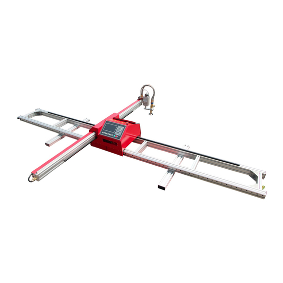
Voyager as well. 1.4. Composition Voyager consists of a support structure and a central control unit. The support structure composed of two longitudinal rails (Y Axis). The stability and rigidity of the rails are guaranteed by two transversal beams. WWW.ARCBRO.COM Unique Solution... -
Page 9: Safety
17. Handling means: because of equipment base guide at both ends long enough, with a handheld parts, meanwhile, weight at about 75kg equipment two young people can raise, note carefully handled and must ensure that equipment in a horizontal position(show as next picture) WWW.ARCBRO.COM Unique Solution... -
Page 10: Caution Sign
⑶: Be careful equipment dumping or tip over. 18. The machine should be each half a month for rack-and pinion with lubricating oil. 19: The machine put in place before the ground level, ensure 2.2 Caution sign WWW.ARCBRO.COM Unique Solution... -
Page 11: Packing List
The boxes have to be carried with care always and with the top cover up during handling and transportation. 3.2. Packing List Open the top cover of the boxes, and remove all the screws fixing the cover to the box body. The Voyager transportation boxes contain: Name Name WWW.ARCBRO.COM Unique Solution... -
Page 12: Installation
Service Support Spirit CNC control system Cross beam Frame rail ARCBRO customized USB pen ARCBRO Wizard auto nesting software Voyager User Manual Sliding blocks Torch height controller (THC) Torch holder: Mechanical control holder (Auto Ground wire control holder for plasma is optional) - Page 13 4. Take out the 16 bolts, plug in 8 pieces for each side, and tighten them with the corresponding nut show as picture 3. Picture3 tighten all the screws one by one Picture 4 the connected rail 5. Overturn the rail (upside down) 180 degree to make the rail facing downward. show as picture 5 WWW.ARCBRO.COM Unique Solution...
- Page 14 Repeat the last step, assemble the other longitudinal cushion block, and have the centre of the Transversal cushion block fixed to the joint of the frame. Picture 6 the assembly for the Transversal cushion blocks on the joint of the rails WWW.ARCBRO.COM Unique Solution...
- Page 15 2 channels from the end of the frame. show as picture 8 Repeat the last step, assemble another Transversal cushion block, and have them fixed to the point that 1000mm to each end of the frame. WWW.ARCBRO.COM Unique Solution...
-
Page 16: Installation Of The Cnc Controller
2. Align the wheels of the Controller unit and the guiding rail, Push the Controller unit to slide in along the Guide Rail, Show as Picture 4 and Picture 5. Push the Central Unit to the direction show as the picture Central Unit installation- detail picture WWW.ARCBRO.COM Unique Solution... -
Page 17: Ground Wire Connection
Find the Ground wire point on the longitudinal rail frame (100mm from the end); Plug the nut into the channel and screw it up; Clamp its other end to the plate you want to cut. 9.5 Cable Connection instruction for Auto Plasma cut WWW.ARCBRO.COM Unique Solution... - Page 18 9.5.3 Torch installation and height adjustment: Adjust the screw of the torch holder to insert the Torch; Fix the torch vertically in right position; Connect the THC cable and attach the red IHS wire onto torch Shield. WWW.ARCBRO.COM Unique Solution...
-
Page 19: Connection Instruction For Auto Flame Cut
Propane cutting nozzles 4 pcs ARC153065 9.6.1 Device Instruction Function: Automatically adjust the torch Height according to level difference of the steel plate. Work theory: To feel the distance between the capacity ring sensor and the steel plate, then WWW.ARCBRO.COM Unique Solution... - Page 20 Push down the knob on Wiring Panel of Controller for Flame mode; Set the proper SET VOLTAGE (default value is 220 for Carbon Steel thickness range 10-30mm), IHS value by the screw on the THC, you can go to the Controller to start an Auto flame cut. WWW.ARCBRO.COM Unique Solution...
-
Page 21: Installation Of Nesting Software
1 unit Your device The ARCBRO Wizard nesting software package contains one CD and one dongle. The software installation file and function instruction videos are written in the CD for your reference. Match with the PC system: WINDOWS XP, WIN7, WIN8, WIN8.1 and WIN10, and Parallel. -
Page 22: Functional Overview
Compatible with many blanking software such as IBE(Germany), FASTCAM, etc. Operation menu both in Chinese and English, dynamic graphic display, 8-times zoom, free point automatic tracking, USB disk program and timely software upgrade. WWW.ARCBRO.COM Unique Solution... -
Page 23: Technical Specifications
1 to 65535 Memory space: 32M-64M oversized memory capacity for user program and no restriction to machining program Machine case size: 298×202×95.2(mm) Operation temperature: 0 to +40℃; storage temperature: -40 to +60℃ WWW.ARCBRO.COM Unique Solution... -
Page 24: Main Menu
[F2] MAN : To manually control the position of cutting nozzle [F3] Edit : To edit/modify/input/output the machining program [F4] SETUP : To set system parameters [F5] DIAGNOSE : To check the input/output information of cutting machine [F6] LIBMINIT : To set normal pattern and plan material WWW.ARCBRO.COM Unique Solution... - Page 25 [G] [G] [3] Initial Setting : A dialog box as follows will appear: File format: to format user's program space; Parameter: To restore the factory parameter setting; ENGLISH: Alternating between Chinese and Fig.7.2 Initial setting dialog box WWW.ARCBRO.COM Unique Solution...
-
Page 26: Automatic Function(Auto)
In the main menu, press [F1] to enter the automatic function window, as shown in the figure below. Piercing Hole Program Active speed Kerf multiplying factor Heavy-current control Pattern Function Display Space Input/output indication Machining Coordinate Work mode parameter indication Plasma Mode Machining Program Flame mode Fig. 8.1 Automatic Function (AUTO) Window WWW.ARCBRO.COM Unique Solution... -
Page 27: Description Of Automatic Mode Window
The bottom indicators show the status of 8 output ports, ○ indicating no signal output and ● indicating signal output. See the description of DIAGNOSE function for the definitions of input/output ports. 8.1.5 Machining Parameters Indication This zone indicates various parameter values in the current machining mode. WWW.ARCBRO.COM Unique Solution... -
Page 28: Selection Of Coordinate Unit
If [X] key is pressed, the system will run the program at top speed without executing M command. This feature is often used to position quickly or check the working size of steel plate. This operation can be paused at any moment or cancelled by pressing [X] key one more times. WWW.ARCBRO.COM Unique Solution... -
Page 29: Y] Au-Spd
[Q] key is used to return the pattern to original size. The display position of pattern is moveable by pressing [↑], [↓], [←] and/or [→] key. 8.2.5[F5] KERF This key is used to reminder input of kerf compensating width; if no necessary to compensate (usually in blanking), simply enter 0. WWW.ARCBRO.COM Unique Solution... -
Page 30: F6] Assi
Aim the cutting torch at the baseline and press [F3] to set the end point of measurement. 3) At this moment, the rotation angle of the datum line is calculated. After the rotate function WWW.ARCBRO.COM Unique Solution... -
Page 31: F4] Mirr
[F], [F↑] and [F↓] key. 8.3.2Machining Speed Automatic multiplying factor is used to adjust machining speed. Machining Speed= machining speed limit * machining multiplying factor, where the automatic multiplying factor is adjustable with [F], [F↑] and [F↓] key. WWW.ARCBRO.COM Unique Solution... -
Page 32: 3Start Of Automatic Mode
4) [Emergency Stop] key: It is an external key with signal received from the input port(refer to "External Input Ports" for details). If emergency stop is validated, all the movement will stop and no output will go on. It is used for emergency case. WWW.ARCBRO.COM Unique Solution... -
Page 33: Adjustment Of Cutting Position
IGN(ignition), PREHEA(piercing preheat), CUT(cutting oxygen), etc. Tip: The system will continue to process from the breakpoint location if [PIERCE] key is pressed after preheating. WWW.ARCBRO.COM Unique Solution... -
Page 34: Original Path Return
8.5.2 Return at G00(when reach a piercing point) In the process of return, the cutting torch will stop at G00 or a piercing point for operator to select going on return or advancing. WWW.ARCBRO.COM Unique Solution... -
Page 35: Repeat The Above Operation Procedure Until The Desired Effect Is Achieved
WWW.ARCBRO.COM Unique Solution... -
Page 36: Breakpoint Restoration Process
CUT(cutting oxygen), etc. Tip: The system will continue to process from the breakpoint location if [PIERCE] key is pressed after preheating. If press [ESC] key when a breakpoint is found, the system will exit machining mode. WWW.ARCBRO.COM Unique Solution... -
Page 37: 2Attention
2) For the latter case, the reference point is used for positioning(REF POSITION option). 3) For these two options, the system will prompt an option menu as shown below after start-up: Fig. 8.6 Option dialog box prompted by the system after machining start if SECTION machining is selected WWW.ARCBRO.COM Unique Solution... -
Page 38: Move Hole For Thick Plate
Fig. 8.7 Option dialog box prompted by the system after reach piercing point if edge piercing method is selected 8.8.1HOLE To pierce at the original position, which is often used for boring. WWW.ARCBRO.COM Unique Solution... -
Page 39: Move Hole
2) Press [START] key at the end of preheat. The cutting torch will reach the piercing point along a straight line at selected cutting speed and then go on machining. 8.8.3 NO HOLE Instead of piercing, the system moves through the current piercing position to next, and new piercing prompt appears. WWW.ARCBRO.COM Unique Solution... -
Page 40: Man(Manual Mode)
Pattern Function Display keys Space Input/output indication Workmode Coordinates Machining indicating zone Parameters Indication Main menu of manual function Manual mode window (plasma cutting operation) Manual mode window (flame cutting operation) Fig.9.1 Manual mode window WWW.ARCBRO.COM Unique Solution... -
Page 41: Description Of Manual Mode Window
Pick up two points([F2] for setting P-START and [F3] for P-END). The system will calculate automatically the rotation angle. Select the ROTATE function in automatic mode. After acknowledged, the system will start the machining program at the appointed rotation angle. Note: Counter clockwise direction is taken as positive angle. WWW.ARCBRO.COM Unique Solution... -
Page 42: F6】 Cls-Co
It is allowed to adjust the speed quickly by pressing [F] key in this window. A pull-down menu will appear with 8 speed multiplying factors available for selection with [↑] and/or [↓] key: 5%, 20%, 30%, 40%, 50%, 60%, 80% and 100%. And then, press RETURN key to acknowledge the selection. WWW.ARCBRO.COM Unique Solution... -
Page 43: Edit Mode
[ESC] key is pressed, the load function will be abandoned. 10.1.3【F3】SAVE To save program. After a program is edited and ready to save, the system will prompt: Enter program name: 1234.TXT WWW.ARCBRO.COM Unique Solution... -
Page 44: F4】Dele
[F1] Input: to transmit program from USB disk to the machining program space. [F2] output: to output the machining program to USB disk from the machining program space. 10.1.7. 【F7】SEARCH STRING This feature is not provided yet. It is reserved for subsequent upgrading. WWW.ARCBRO.COM Unique Solution... -
Page 45: Command System
Note 2: In command execution, the previous program has higher priority than the following one; for the same program, M, S and T command haver higher priority than G command. 11.2. Coordinate System This CNC system uses standard rectangular coordinate system, as shown in the figure below. WWW.ARCBRO.COM Unique Solution... -
Page 46: G: Basic Preparatory Commands
Machining to point(600,200) along a straight line, equivalent G01/U500/V100 Exemple 2: G92 X0 Y0 Absolute coordinate system, by default G00 X100 Y100 Quickly reach point(100, 100) G01 X600 Y200 Machining to point(600,200) along a straight line 3) G20/G21: English/Metric Commands WWW.ARCBRO.COM Unique Solution... - Page 47 This command makes the torch cut to a designated position along a straight line. As machining movement command, it allows uniaxial or biaxial linear interpolation movement. The feed speed is designated by F command. Format: G01 X[U]n Z[W]n [Fn] G01 PPn [Fn] WWW.ARCBRO.COM Unique Solution...
- Page 48 R is the radius of circle(R is a positive value and can be used to represent radius where circular arc ≤180°). Alternatively, if I and J are designated, R will be not necessary; if R is designated, I and J WWW.ARCBRO.COM Unique Solution...
- Page 49 (L to designate number of cycles) Loop (End mark of loop) Example: N000 G92 X100 Y100 N001 G00 X60 Y80 N002 G22 L5 - Level 1 loop starts. N003 G00 V50 U-25 N004 G22 L5 - Level 2 loop starts. WWW.ARCBRO.COM Unique Solution...
- Page 50 Since cutter compensation is made automatically, there must be G00 Quick Move command before G41 or G42 commands so as to assure the position of cutting torch is corrected. Behind G40 the end mark of cutter compensation, a G00 command is necessary to adjust the position back. WWW.ARCBRO.COM Unique Solution...
-
Page 51: M Auxiliary Commands
Lower the cutting torch(and count the time delay of lowering torch, see M71); 2. If hole positioning option is enabled(refer to SETUP), the cutting torch will move down until hit the lower limit switch. Then the cutting torch will move up until the hole positioning time delay is up. WWW.ARCBRO.COM Unique Solution... - Page 52 This command is used before piercing operation, opposite to M70 in function and little bit smaller in value. Because of gravity, the lowering action is faster than lifting action. Operation sequence: turn on the torch lowering switch(M16), count the time delay of WWW.ARCBRO.COM Unique Solution...
- Page 53 (M14). After count the time delay of torch positioning (refer to 7.4 for plasma parameter), the lifting torch will stop(M15). M80: Master switch All the output ports will be turned off if the command of M80 is executed. WWW.ARCBRO.COM Unique Solution...
-
Page 54: Setup (Parameter Setting)
Torch positioning delay, M commands for arc ignition, M commands for arc breaking, arc voltage test option, positioning test option and piercing delay. Control parameters Flame/plasma mode selection, machining speed limit, MOVE HOLE option, metric/English selection, etc. WWW.ARCBRO.COM Unique Solution... -
Page 55: Setup(Parameter Setting)
Maximum speed limit----The top speed of running system in manual control mode and in execution of G00 command, in mm/min. or inch/min. Machining speed limit-----The top machining speed in flame/plasma machining operation, in mm/min. or inch/min. WWW.ARCBRO.COM Unique Solution... -
Page 56: System Parameters
Fig. 12.2 Speed parameters setting 8) Circular corner transitional radius ---- Refer to circular corner transitional option. 12.2.2. System parameters In the SETUP submenu, press [F2] key to enter system parameters setting window, as shown in Fig.12.3. WWW.ARCBRO.COM Unique Solution... - Page 57 Mechanical origin ---- A special point on the machine set with proximity switch. If mechanical origin is not to be used, set it to zero. Unit: mm(or inch) Reference point ---- It is defined as the machining origin of program and established automatically when a program is run(G92). Unit: mm(or inch). WWW.ARCBRO.COM Unique Solution...
-
Page 58: Flame Cutting Parameters
Lowering delay of cutting torch——The time delay when M71 command is executed, in second. Refer to 6.4 for M auxiliary commands. Lifting delay of piercing torch——The time delay when M72 command is executed, in second. Refer to 6.4 for M auxiliary commands. WWW.ARCBRO.COM Unique Solution... -
Page 59: Plasma Parameters Setting
Height control disabling distance at corner ----- At the transition or corner of two program segments, speed and arc voltage might change, causing unexpected nozzle knock; therefore, the system will automatically disable the height control in such a distance from the endpoint of program segment, in mm. WWW.ARCBRO.COM Unique Solution... -
Page 60: Control Parameters Setting
Remarks SETUP zone main menu Fig. 12.6 Control parameters menu Flame/plasma option——Take 0 for flame machining and 1 for plasma machining. Move hole option——0 stands for disabling the option and 1 for enabling the option. WWW.ARCBRO.COM Unique Solution... - Page 61 English system(G20). Take 1 for English system, which will have parameters, display and coordinates expressed in English unit (inch), though it supports machining program in metric program(G21). Attention: Please be cautious to make any change if no idea of the specific application of a parameter! WWW.ARCBRO.COM Unique Solution...
-
Page 62: Libminit (Library Of Patterns)
2) When the parameters are entered, the control system will drawn the pattern based on the entered parameters, which is very helpful to graphic check. In the system main menu, press [F6] to enter the LIBMINIT(Library of Patterns). Fig. 13.1 LIBMINIT Feature(Library of Patterns) WWW.ARCBRO.COM Unique Solution... -
Page 63: Selection Of Pattern Elements
Row number----Row number of machined parts array Column number----Column number of machined parts array Row pitch----Distance between rows. Column pitch----Horizontal distance between machined parts Row offset----The deviation of raw misplacement, as shown in Fig. 13.3. Fig. 13.2 Pattern setting menu WWW.ARCBRO.COM Unique Solution... -
Page 64: User Defined Module
Simply copy this program into the file system. The 17th pattern element is self-defined. If no new module is self-defined, the system will take the old module automatically. This module is allowed to use for Layout and Rotate features, but no parameter to set . WWW.ARCBRO.COM Unique Solution... -
Page 65: Diagnose
Output state Input port Input state In Plasma Operation In Flame Operation 14.1 Check Input/output Ports The system diagnosis will show the hardware resources available. In DIAGNOSE window, it is allowed to check the state of input/output port. WWW.ARCBRO.COM Unique Solution... -
Page 66: Output Check
Let the system to show the state of active optical isolation input ports. 0 stands for low potential(grounding) while 1 stands for high potential(24V or overhead). See "Definitions of Input/output Ports" for the symbol definitions of input ports. WWW.ARCBRO.COM Unique Solution... -
Page 67: Appendix I: Instructions For Software Upgrading Operation Of Sh-2012Ah
USB disk. If these two factors are assured, try to upgraded the program again following the specific operation procedure. WWW.ARCBRO.COM Unique Solution... -
Page 68: Appendix Ii: Troubleshooting
Motor fails t ed is zero or too hig arameters before making any m o run h, the speed regulatio odification. n time is too short an d the electronic gear or pulse equivalency is appropriate to be zer WWW.ARCBRO.COM Unique Solution... - Page 69 G, G and 3 in the system main n manual/aut window successively. Save the p omatic mod arameters in parameter setting mode. Restart the system and fi ll the recorded value of electron WWW.ARCBRO.COM Unique Solution...
- Page 70 The system Initialize the system if Initialize the system parameters. can only any parametric probl machine straight line WWW.ARCBRO.COM Unique Solution...
- Page 71 25. Check if the four rela Replug or replace the relays. No system ys on the rear panel output are reliably connecte d, if the relay operati on is normal and if t he contact is function WWW.ARCBRO.COM Unique Solution...
Need help?
Do you have a question about the Voyager Series and is the answer not in the manual?
Questions and answers