Advertisement
Quick Links
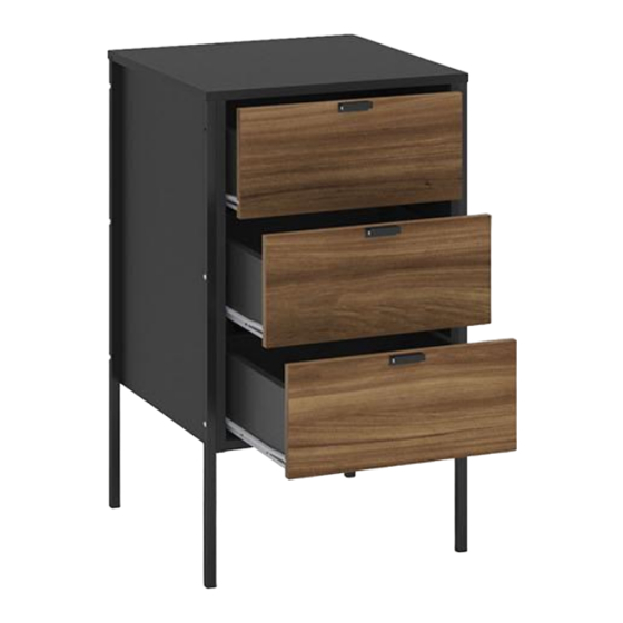
Assembly Instructions
Thank you for
purchasing a
Birlea product.
Are you happy with your purchase?
Yes:
That's great, we would love to hear more from you. Please leave us a review on
our social media channels or Trustpilot. Your feedback will be greatly appreciated.
No:
If for any reason there is something missing, indifferent or incorrect with
your order, please contact the retailer you purchased the item from. We will
work with the retailer to resolve your issue as quickly as possible.
For a chance to win a Love 2 Shop voucher
simply post a picture of your new product
on your preferred social channels tagging
Birlea Furniture and using the hashtag
#ShareYourStyle and #Birlea. One winner
will be selected at random each month.
To view our full terms and conditions please visit our website. www.birlea.com
www.birlea.com
Advertisement

Subscribe to Our Youtube Channel
Related Manuals for Birlea OPUS 3 DRAWER STORAGE CABINET


Summary of Contents for Birlea OPUS 3 DRAWER STORAGE CABINET
- Page 1 #ShareYourStyle and #Birlea. One winner Birlea product. will be selected at random each month. To view our full terms and conditions please visit our website. www.birlea.com Are you happy with your purchase? Yes: That’s great, we would love to hear more from you. Please leave us a review on our social media channels or Trustpilot.
- Page 2 Assembly Video For a step by step guide on how to build our Opus 3 Drawer Storage Cabinet visit our YouTube channel BirleaFurnitureLtd ’ or alternatively scan the below code on your smart phone. How to scan a QR code from an apple device Step One: Open up the camera app Step Two:...
-
Page 3: Health And Safety
ASSEMBLY INSTRUCTIONS OPUS 3 DRAWER STORAGE CABINET IMPORTANT: READ THESE INSTRUCTIONS CAREFULLY BEFORE ASSEMBLING OR USING YOUR OPUS 3 DRAWER STORAGE CABINET. PLEASE KEEP THESE INSTRUCTIONS FOR FUTURE REFERENCE. HEALTH & SAFETY: DO NOT use this item if any parts are missing, damaged or worn. - Page 4 Vendor: S000139 Parts List Part Descripion Bottom Base Left Side Right Side Front of Drawer Drawer Back Drawer of Bottom Coast Left Side of Drawer Right Side of Drawer Page of...
- Page 5 Vendor: S000139 Hardware List Part Descripion Flanged head screw Glue Flat head screw Union head screw Flat head screw Bushing 8 x 30 mm Wooden Dowel Strap Handle Foot F18A Union flat head screw F18B Union flat head screw Structural Screw Allen Key Structural Screw Cover Simple Minifix Screw...
- Page 6 Vendor: S000139 Step 1: Insert hardware parts E using small mallet (not provided). DO NOT use any power tools as this may damage the frame and will invalidate any claim. Step 2: Insert hardware parts VB using hardware part P5 and screwdriver (not provided). Insert hardware part E using a small mallet (not provided).
- Page 7 Vendor: S000139 Step 4: Insert hardware part J using the a screwdriver (not provided). DO NOT use any power tools as this may damage the frame and will invalidate any claim. Step 5: Attach the hardware part J to the Drawer Front (05) using the a screwdriver (not provided). Then attach the hardware part E to the Drawer Back (06) using a mallet (not provided).
- Page 8 Vendor: S000139 Step 7: Attach the Bottom Base (02) to the Left Side (03) using hardware part G, H and I. DO NOT use any power tools as this may damage the frame and will invalidate any claim. Step 8: Attach the feets F12 to the Left Side (03) using hardware part F18A and F18B and the a screwdriver (not provided).
- Page 9 Vendor: S000139 Step 9: Join the Right Side (04) to the assembled section using hardware part H, G and I. DO NOT use any power tools as this may damage the frame and will invalidate any claim. Step 10: Attach the feets F12 to the Right Side (04) using hardware part F18A and F18B and the a screwdriver (not provided).
- Page 10 Vendor: S000139 Step 11: Join the Coast (16) to the assembled section. DO NOT use any power tools as this may damage the frame and will invalidate any claim. PAINTED SIDE DOWN Step 12: Join the Top (01) to the assembled section using hardware part L and a screwdriver (not provided). DO NOT use any power tools as this may damage the frame and will invalidate any claim.
- Page 11 Vendor: S000139 Step 13: Insert hardware part o1 and A8 using the a screwdriver (not provided). DO NOT use any power tools as this may damage the frame and will invalidate any claim. 1º 2º Step 14: To secure the item to the wall use hardware parts A, B3 and E9 using a drilling machine (not provided) and a screwdriver (not provided).Then attach hardware part S to the item with a screwdriver (not provided).
- Page 12 Vendor: S000139 Step 15: Attach the Left Side of Drawer (78) and the Right Side of Drawer (79) to the drawer back (06) and the bottom of drawer (07) using the hardware part O and a screwdriver (not provided). DO NOT use any power tools as this may damage the frame and will invalidate any claim. Step 16: Attach the Front of Drawer (05) using the hardware part L and A1 and a screwdriver (not provided).
- Page 13 Vendor: S000139 Step 17: Attach the hardware part E16 to the Front of Drawer (05) using hardware part A16 and A17 and a screwdriver (not provided). Insert the hardware part M to the Left Side of Drawer (78) and the Right Side of Drawer (79).
-
Page 14: Additional Information
If you have any issues with your item please contact the retailer directly you purchased it from who will be able to resolve any issues with Birlea. Why don't you send us photos of your assembled furniture to info@birlea.com to be shared in our #birleahome feature on Instagram.
Need help?
Do you have a question about the OPUS 3 DRAWER STORAGE CABINET and is the answer not in the manual?
Questions and answers