Table of Contents
Advertisement
Quick Links
Familiarising yourself with the moped
4
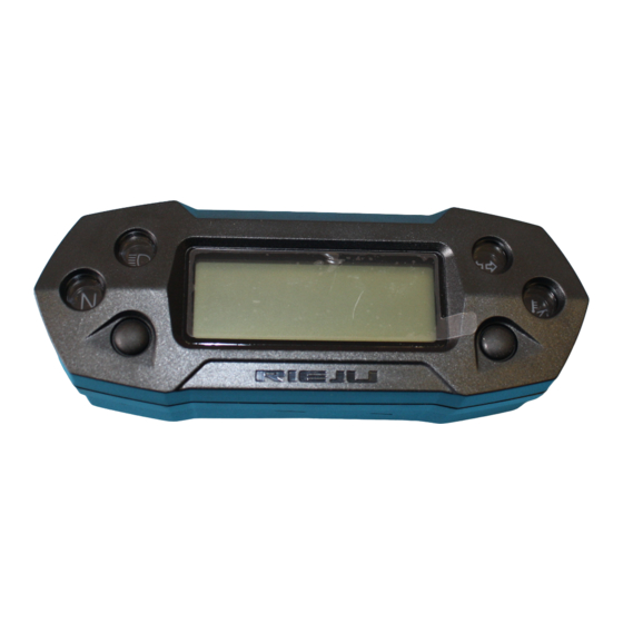
KOSO
3
INSTRUMENT PANEL
1-
Turn indicators indicator light
This indicator light flashes when the turn indicator switch is moved to the left or to
the right.
2-
Oil temperature indicator light
This indicator light comes on when the oil temperature is too high.
3-
"N" neutral indicator light
This indicator light comes on when the transmission is in the neutral position.
4-
Main beam indicator light.
This indicator light comes on when the headlight is on main beam.
Chassis
1
2
F-9
Advertisement
Table of Contents

Subscribe to Our Youtube Channel
Related Manuals for RIEJU KOSO


Summary of Contents for RIEJU KOSO
- Page 1 Familiarising yourself with the moped Chassis KOSO INSTRUMENT PANEL Turn indicators indicator light This indicator light flashes when the turn indicator switch is moved to the left or to the right. Oil temperature indicator light This indicator light comes on when the oil temperature is too high.
- Page 2 Electrical system Chassis DIAGRAM OF THE KOSO INSTRUMENT PANEL SENSORS Checking the functioning of the indicator lights. Temperature and oil indicator: Checking these requires making a bridge to earth with each cable corresponding to the graphic for the instrument panel.
- Page 3 Electrical system Chassis PROGRAMMING KOSO INSTUMENT PANEL N.B.: The notes contain detailed information about the installation. ( ) Processes to be followed is obligatorily to avoid the problems caused by an incorrect installation. PRESS PRESS THE BUTTON DOWN FOR THREE SECONDS...
- Page 4 Electrical system Chassis Adjustment of the speed measurement unit. On the main screen, hold down the selection and adjustment buttons for 3 seconds to access the adjustment of the speed measure- ment unit. Press the adjustment button to select the unit of measurement.
- Page 5 Electrical system Chassis Press the selection button to access the tyre circumference adjustment. E.g.: The tyre circumference is 1,300 mm. Press the selection button to change to the digit to be adjusted. E.g.: The original adjust- ment is 1,000mm. The 1 flashes. N.B.: Tyre circumference adjustment interval: 300~2,500 mm;...
- Page 6 Electrical system Chassis E.g.: the sensor point to be adjusted is 6. Press the selection button to change to the digit to be adjusted. E.g.: the original setting is 1 point. The 0 flashes. N.B.: Sensor point adjustment interval: 1~60 points.
- Page 7 Electrical system Chassis KOSO WIRING DIAGRAM...
Need help?
Do you have a question about the KOSO and is the answer not in the manual?
Questions and answers