Table of Contents
Advertisement
Quick Links
User Manual of EM730/EM730E Series Inverter
Thank you for choosing SINEE's EM730/EM730E series inverter.
Document No.: 31010183
Release time: June 2020
Version: 100
The EM730/EM730E series inverter is a high-reliable and small-sized universal inverter
launched by SINEE. EM730 supports three-phase AC asynchronous motors, while EM730E
supports permanent magnet synchronous motors. They support a variety of drive control
technologies, such as the vector VF (VVF) control and speed sensorless vector control (SVC);
speed output and torque output; and Wi-Fi access and background software debugging.
Features of the EM730/EM730E series inverter:
Support debugging by the mobile phone APP or monitoring of the inverter status;
Support Wi-Fi module or serial port access;
Rich and convenient PC background software functions;
No need for derating at the ambient temperature of 50 ℃;
Support "one-key shuttle" for fast and accurate speed adjustment;
Perfect protections: Protections against the short circuit, overcurrent, overvoltage,
overload, overheating, etc.
Before using the EM730/EM730E series inverter, please read this manual carefully
and keep it properly.
While connecting the inverter to motor for the first time, please select the motor type
(asynchronous or synchronous) correctly and set the motor nameplate parameters: rated
power, rated voltage, rated current, rated frequency, rated speed, motor connection, rated
power factor, etc.
Since we are committed to continuously improving our products and product data, the data
provided by us may be modified without prior notice.
For the latest changes and contents, please visit www.sinee.cn.
Preface
1
Advertisement
Table of Contents

Related Manuals for Sinee EM730 Series


Summary of Contents for Sinee EM730 Series
- Page 1 Version: 100 The EM730/EM730E series inverter is a high-reliable and small-sized universal inverter launched by SINEE. EM730 supports three-phase AC asynchronous motors, while EM730E supports permanent magnet synchronous motors. They support a variety of drive control technologies, such as the vector VF (VVF) control and speed sensorless vector control (SVC);...
- Page 2 User Manual of EM730/EM730E Series Inverter Safety precautions Safety definition: Safety precautions are divided into the following two categories in this manual: Danger: The dangers caused by nonconforming operations may include serious injuries and even deaths. Warning: The danger caused by nonconforming operations, including moderate or minor injuries and equipment damage.
- Page 3 User Manual of EM730/EM730E Series Inverter from combustibles; otherwise, a fire may be caused! Do not loosen the fixing bolts of components, especially those with red marks! Warning Never make wire connectors or screws fall into the inverter; otherwise, the inverter may be damaged! Install the inverter in a place with little vibration and exposure to direct sunlight.
- Page 4 User Manual of EM730/EM730E Series Inverter Before power-on: Danger Make sure that the voltage level of the input power supply is consistent with the rated voltage of the inverter; and the input terminals (R, S, T) and output terminals (U, V, W) of the power supply are connected correctly.
- Page 5 User Manual of EM730/EM730E Series Inverter During operation: Danger Do not touch the cooling fan, radiator and discharge resistor to feel the temperature; otherwise, burns may be caused! Non-professional technicians must not test signals when the controller is in operation; otherwise, personal injury or equipment damage may be caused! Warning Prevent any object from falling into the inverter in operation;...
- Page 6 User Manual of EM730/EM730E Series Inverter Operation above power frequency This inverter can provide the output frequency of 0.00Hz to 600.00Hz/0.0Hz to 3000.0Hz. When the motor needs to operate above the rated frequency, please consider the capacity of the mechanical device. About motor heat and noise Since the inverter outputs PWM waves, containing some harmonics, the temperature rise, noise and vibration of the motor will be slightly more than those in operation at the power frequency.
- Page 7 User Manual of EM730/EM730E Series Inverter Contents Preface ......................1 Safety precautions ................... 2 Precautions ........................2 Precautions ........................5 Chapter 1 Overview ..................10 1.1 Model and Specification of EM730/EM730E Series Inverter ........10 1.2 Detailed Introduction to Running Status of EM730/EM730E series Inverter ... 13 Chapter 2 Installation ...................
- Page 8 User Manual of EM730/EM730E Series Inverter 5.1 Inverter Commissioning Process ................57 5.2 Confirmation before Power-on ................. 58 5.3 Inverter Status Confirmation after Power-on ............58 5.4 Precautions for Application Macro Setting ............... 58 5.5 Start and Stop Control ....................59 5.6 Common Process Parameters of Inverter..............
- Page 9 User Manual of EM730/EM730E Series Inverter 7.20 F19 protection record parameter group ..............279 7.21 F27 winding and unwinding application macro parameter group ......282 Chapter 8 Motor Parameter Self-identification ........298 8.1 Motor Parameter Self-identification ............... 298 8.2 Precautions before Self-identification ..............299 8.3 Self-identification Steps ..................
- Page 10 User Manual of EM730/EM730E Series Inverter Chapter 1 Overview 1.1 Model and Specification of EM730/EM730E Series Inverter Rated voltage of power supply: Three-phase AC 340-460V, three-phase/single-phase AC 200V-240V; Applicable motor: Three-phase AC asynchronous motor (EM730) and permanent magnet synchronous motor (EM730E).
- Page 11 User Manual of EM730/EM730E Series Inverter EM730/EM730E-160-3 ★ Correct selection of the inverter: The rated output current of the inverter is greater than or equal to the rated current of the motor, taking into account the overload capacity. ★ The difference between the rated power of the inverter and that of the motor is usually recommended not to exceed two power segments.
- Page 12 User Manual of EM730/EM730E Series Inverter accuracy Acceleration and 0.01 s to 600.00 s / 0.1 s to 6,000.0 s / 1 s to 60,000 s deceleration time Voltage/frequency Rated output voltage: 20% to 100%, adjustable characteristics Reference frequency: 1Hz to 600Hz/3,000Hz Fixed torque boost curve Torque boost Any V/F curve is acceptable.
- Page 13 User Manual of EM730/EM730E Series Inverter Multi-function output of one open collector and one relay Digital output Maximum output current of the collector: 50 mA; terminal Relay contact capacity: 250VAC/3A or 30VDC/1A, EA-EC: normally open; EB-EC: normally closed Analog output One multi-function analog terminal output terminal M1: 0-10V/0-20mA multi-function analog output terminal...
- Page 14 User Manual of EM730/EM730E Series Inverter Normal running status: Upon receiving a valid start command (from the keyboard, control terminal and communication), the inverter will have the output based on the set input requirements, driving the motor to rotate. ...
- Page 15 User Manual of EM730/EM730E Series Inverter Setting of main frequency source A 0: synthetic frequency of main Setting of auxiliary and auxiliary channels frequency source B Setting of main and auxiliary operations Synthetic 1: AI1 * synthetic frequency of main Options of Setting of main frequency...
- Page 16 User Manual of EM730/EM730E Series Inverter If the terminals are unavailable, the current setting channel is determined by the function code F00.04, and final settings are obtained through UP/DOWN setting calculation. 0: digital frequency setting F00.07 1:AI1*F00.16 2:AI2*F00.16 5: HDI*F00.16 Gain of 6: SCI*F00.16 auxiliary...
- Page 17 User Manual of EM730/EM730E Series Inverter The digital setting, analog input setting, high-speed pulse input setting, communication setting, digital potentiometer setting or multi-segment torque setting can be applied. Fig. 1-5 details the input modes of EM730/EM730E series inverters with the set torque. Torque of the n segment Compensation for...
- Page 18 User Manual of EM730/EM730E Series Inverter Running Running command command Reverse Stop Forward Forward Stop Reverse Stop Stop 0: closed 1: disconneted 0: closed 1: disconneted (a) Two-line running mode 0 (F00.03=0) (b) Two-line running mode 1 (F00.03=1) Run button Forward Stop button button...
- Page 19 User Manual of EM730/EM730E Series Inverter Chapter 2 Installation 2.1 Product check Danger Never install the inverter damaged or with some parts missing. Otherwise, injuries may be caused. When you get the product, please check it according to Table 2-1. Table2-1 Check Items Item to be confirmed Confirming methods...
- Page 20 User Manual of EM730/EM730E Series Inverter EM730-4R0-3B Product series: M730:EM730 inverter B: Built-in braking unit EM730E:EM730E inverter Power (kW) of the supporting motor Input power voltage level: of inverter 2: Single/three-phase 220V Example: 4R0: 4.0kW 3: Three-phase 380V 0.37:37kW 2.2 Outline dimensions and installation dimensions EM730/EM730E series inverters involve 25 specifications, two types of appearance and ten installation sizes, as shown in Fig.
- Page 21 User Manual of EM730/EM730E Series Inverter (b) Appearance of EM730/EM730E-030-3B to EM730/EM730E-075-3 inverters...
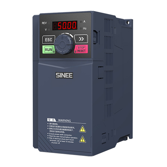
- Page 22 User Manual of EM730/EM730E Series Inverter Appearance of EM730/EM730E-090-3 to EM730/EM730E-160-3 inverters 70.6 (d) EM730 keyboard appearance Fig.2-1 Outline Dimensions of EM730/EM730E Series Inverter and Keyboard...
- Page 23 User Manual of EM730/EM730E Series Inverter Table 2-2 Outline and Installation Dimensions of EM730/EM730E Series Inverter Specifications EM730/EM730E-0R4-2B EM730/EM730E-0R7-2B EM730/EM730E-1R5-2B EM730/EM730E-2R2-2B EM730/EM730E-0R7-3B EM730/EM730E-1R5-3B EM730/EM730E-2R2-3B EM730/EM730E-4R0-3B EM730/EM730E-5R5-3B EM730/EM730E-7R5-3B EM730/EM730E-011-3B EM730/EM730E-015-3B EM730/EM730E-018-3B EM730/EM730E-022-3B EM730/EM730E-030-3 EM730/EM730E-030-3B EM730/EM730E-037-3 EM730/EM730E-037-3B EM730/EM730E-045-3 EM730/EM730E-055-3 EM730/EM730E-075-3 EM730/EM730E-090-3 EM730/EM730E-110-3 EM730/EM730E-132-3 EM730/EM730E-160-3...
- Page 24 User Manual of EM730/EM730E Series Inverter 2.3 Installation Site Requirements and Management Attention 1 、 When carrying the inverter, hold its bottom. If you hold the panel only, the body main fall to hit your feet. 2 、 Install the inverter on non-flammable boards (e.g. metal). If the inverter is installed on a flammable object, a fire may occur.
- Page 25 User Manual of EM730/EM730E Series Inverter 2.3.3 Preventive measures Take protective measures to the inverter during installation to prevent metal fragments or dust generated in drilling and other processes from falling into the inverter. Remove the protection after installation. 2.4 Installation Direction and Space The EM730/EM730E-1R5-3B inverters and above are equipped with the cooling fan for forced air cooling.
- Page 26 User Manual of EM730/EM730E Series Inverter Chapter 3 Wiring 3.1 Connection of Peripheral Device The standard connection between the EM730/EM730E series inverter and peripheral devices is shown in Fig.3-1. Power supply Circuit breaker or leakage protection switch Contactor AC input reactor BR 100 Braking unit Input-side noise filter Braking resistor...
- Page 27 User Manual of EM730/EM730E Series Inverter 3.2 Wiring of Main Circuit Terminal 3.2.1 Composition of main circuit terminal The main circuit terminal of the EM730/EM730E series inverter consists of the following parts: Three-phase AC power input terminals: R, S, T ...
- Page 28 User Manual of EM730/EM730E Series Inverter b) Schematic Diagram of Terminals (380V, 2.2kW-4.0kW) c) Schematic Diagram of Terminals (380V, 5.5kW-22kW) (with slight difference in the grounding position)
- Page 29 User Manual of EM730/EM730E Series Inverter d) Schematic Diagram of Terminals (380V, 30kW-37kW) e) Schematic Diagram of Terminals (380V, 45kW-110kW)
- Page 30 User Manual of EM730/EM730E Series Inverter f) Schematic Diagram of Terminals (380V, 132kW-160kW) Fig.3-2 Schematic Diagram of Main Circuit Terminal Layout 3.2.2 Functions of main circuit terminals The functions of the main circuit terminals of the EM730/EM730E series inverter are shown in the following table.
- Page 31 User Manual of EM730/EM730E Series Inverter 3.2.3 Standard wiring diagram of main circuit The standard wiring diagram of the main circuit of the EM730/EM730E series inverter is shown in Fig. 3-3. Wiring of built-in brake unit Wiring of external brake unit B r a k i n g r e s i s t o r (o p t i o n a l Braking resistor...
- Page 32 User Manual of EM730/EM730E Series Inverter MCCB Inverter Fault relay contact Fig.3-4 Connection of Input Circuit Breaker Installation of leakage circuit breaker Since the inverter outputs high-frequency PWM signals, a high-frequency leakage current will be generated. Please use the dedicated leakage circuit breaker with the current sensitivity above 30 mA.
- Page 33 User Manual of EM730/EM730E Series Inverter will cause damage to the rectifier part of the inverter. In this case, please connect a three-phase AC reactor (optional) to the input side of the inverter. This will not only suppress the peak current and voltage, but also improve the power factor of the system.
- Page 34 User Manual of EM730/EM730E Series Inverter MCCB Ordinary noise Inverter filter Other control devices MCCB Inverter Other control Ordinary noise devices filter Fig. 3-6 Incorrect Installation of Noise Filter 3.2.5 Output side wiring of main circuit Wiring of inverter and motor Connect the output terminals (U, V, W) of the inverter to those (U, V, W) of the motor.
- Page 35 User Manual of EM730/EM730E Series Inverter Prohibition of short circuit or grounding of output terminal Do not directly touch the output terminals, or short-circuit the output cable and inverter housing; otherwise, electric shock and short circuit may be caused. In addition, never short-circuit the output cable.
- Page 36 User Manual of EM730/EM730E Series Inverter Solution to inductive interference To suppress the inductive interference on the output side, all output cables can be laid in the grounded metal tubes, in addition to the aforesaid installation of the noise filter. When the distance between the output cable and signal line is greater than 30 cm, the impact of inductive interference will decrease significantly, as shown in Fig.
- Page 37 User Manual of EM730/EM730E Series Inverter When the motor wiring distance exceeds 50 m, connect the output terminals (U, V, W) of the inverter with the dedicated AC reactor (phase capacity: the same as that of the inverter) for inverter output.
- Page 38 User Manual of EM730/EM730E Series Inverter EM730/EM730E-090-3 17.0 ~ 22.0 EM730/EM730E-110-3 EM730/EM730E-132-3 R, S, T, P, +, -, U, V, W EM730/EM730E-160-3 Table 3-1 Cable Dimensions and Terminal Screw Specifications Note: 1: The specifications of the wire are dependent on its voltage drop. Under normal circumstances, the voltage drop calculated by the following formula should be less than 5V.
- Page 39 User Manual of EM730/EM730E Series Inverter 3.2.8 Installation and wiring of braking resistor and braking unit Refer toChapter 10 for the selection and wiring of the braking resistor and braking unit. For the inverter with a built-in braking unit, connect the braking resistor between the inverter terminal (+) and PB terminal.
- Page 40 User Manual of EM730/EM730E Series Inverter grounding terminal output -10V to 10V, 50kΩ input impedance, bipolar Analog voltage input analog voltage input Analog Current or voltage type current/voltage Input range: 0/4-20mA or 0-10V input Analog Analog output voltage/current 0-10V/0-20mA; output accuracy: ± 2% output Program the corresponding terminals by setting function codes, to realize the input...
- Page 41 User Manual of EM730/EM730E Series Inverter keyboard port terminal The upper computer can also be connected through this port for background software debugging. 3.3.3 Wiring of analog input terminal Wiring of AI1 and AI2 terminals with analog voltage signal: When the AI2 terminal is in the mode of analog voltage signal input, the switch J8 on the control panel is set to the voltage mode, as shown in Fig.
- Page 42 User Manual of EM730/EM730E Series Inverter terminal block is set to the current mode. Fig.3-13 Wiring Diagram of External Current Source and AI2 Terminal 3.3.4 Wiring of multi-function input terminal The multi-function input terminals of EM730/EM730E series inverters support the access in the NPN or PNP mode.
- Page 43 User Manual of EM730/EM730E Series Inverter 3.3.5 Wiring of multi-function output terminals The multi-function output terminal Y1 is powered on by the internal 24V power supply of the inverter or an external power supply, as shown in Fig. 3-15: +24V +24V Relay Relay...
- Page 44 User Manual of EM730/EM730E Series Inverter M1 is for analog voltage output Inverter M1 is for analog current output 3.3.7 Wiring of 485 communication terminals The communication terminals A+ and A- are the RS485 communication interfaces of the inverter. The online control of the host (PC or PLC controller) and inverter is performed through the connection and communication with the host.
- Page 45 User Manual of EM730/EM730E Series Inverter RS485 communication interface of host + terminal - terminal Inverter Inverter Inverter Inverter Fig. 3-17 Wiring of Communication Terminals of Multiple Inverters Connection to the host via RS485/RS232 adapter for communication: RS232 Inverter communicatio RS485/RS232 n interface of...
- Page 46 User Manual of EM730/EM730E Series Inverter in the control circuit. The wiring distance should be less than 50 m. Prevent the shield screen from contact with other signal lines and enclosures. The exposed shield screen can be wrapped with insulating tapes. ...
- Page 47 User Manual of EM730/EM730E Series Inverter should be 0.5N.m. 3.4 Extension wiring of keyboard 1) The external keyboard needs to be ordered separately. 2) The external keyboard is connected to the RJ45 port via an ordinary network cable (plug: meeting the EIA/TIA568B standards) prepared by the customer. 3) Connect the RJ45 port of the keyboard to that of the control panel via a network cable.
- Page 48 User Manual of EM730/EM730E Series Inverter Chapter 4 KEYBOARD OPERATIONS 4.1 Keyboard Functions 4.1.1 Structure of LED keyboard The control panel of EM730/EM730E series inverter is a pluggable LED keyboard The LED keyboard has one five-digit LED digital display, four operation buttons, one digital potentiometer, and six status and unit indicators.
- Page 49 User Manual of EM730/EM730E Series Inverter Turn it counterclockwise to select the function code and menu group or decrease the parameter value. Decrease the currently valid reference digital input data. Click it to enter the lower-level menu. Confirm and save the parameter modification, and enable the function code following the current function code.
- Page 50 User Manual of EM730/EM730E Series Inverter Fig. 4-2 Flowchart of Menu Mode Selection 4.2.1 Full menu mode (--A--) In the full menu mode, press the ENTER key to enter the Level 2 menu and select any function code. Then press the ENTER key to enter the Level 3 menu and view or modify the function code.
- Page 51 User Manual of EM730/EM730E Series Inverter Flicker Flicker Flicker bit Flicker bit Flicker bit Flicker bit Flicker bit Flicker bit Flicker bit Flicker bit Flicker bit Flicker bit Flicker bit Fig. 4-3 Flowchart from Power-on to F03.28=5.28 Setting In all menu modes, the user needs to press the ENTER key to save parameter modifications.
- Page 52 User Manual of EM730/EM730E Series Inverter In the Level 3 menu, press the ESC key to abandon parameter modifications. 4.2.2 User-defined mode (--U--) Enter the F11 group of function codes from the full menu mode. Then the user can arbitrarily set the shortcut for the parameter to be accessed frequently. When F11.00 is enabled for the first time, U00.00 will be displayed by default, meaning that the function code defined by default for F11.00 is F00.00.
- Page 53 User Manual of EM730/EM730E Series Inverter code F11.01, and so on to F11.31, 32 in total. Function code modification in the Level 3 menu is equivalent to that in the full menu mode, and the modification method is also the same. In the Level 2 menu of the user-defined mode, turn the potentiometer key on the keyboard, to change the function code defined by F11.00 to that defined by F11.31.
- Page 54 User Manual of EM730/EM730E Series Inverter Flicker bit Flicker bit Flicker bit Flicker bit Fig. 4-5 Function Code Modification in Non-default Mode 4.2.4 Protection information display mode (--E--) In the protection information display mode, press the ENTER key to enter the Level 2 menu.
- Page 55 User Manual of EM730/EM730E Series Inverter parameter will automatically change from the current value to that indicated by F12.33. When the inverter changes from the running status to stop status, the monitoring parameter will automatically change from the current value to that indicated by F12.34. 4.4.2 Editing Mode Quick change in the monitoring mode: When F00.04 is set to “0: digital frequency setting F00.07”, turn the potentiometer key...
- Page 56 User Manual of EM730/EM730E Series Inverter the inverter, and the STOP/RESET key to stop the inverter. 4.6 Other Warning Prompts 4.6.1 P.-ON prompt The P.-ON prompt will be displayed after power-on initialization. 4.6.2 P.-OFF prompt When the voltage drops to 250V (with the soft start disconnected), P-OFF will be displayed, and the keyboard can be operated freely to exit the P.-OFF display and display normal information.
- Page 57 User Manual of EM730/EM730E Series Inverter Chapter 5 Trial run 5.1 Inverter Commissioning Process Fig. 5-1 Inverter Commissioning Flowchart...
- Page 58 User Manual of EM730/EM730E Series Inverter 5.2 Confirmation before Power-on Please confirm the following items before turning on the power supply: Item to be confirmed Confirmation content Check whether the input power voltage is consistent with the voltage of the inverter. Confirm that the circuit breaker has been connected to the Power wiring power supply circuit, and the power cables are correctly...
- Page 59 User Manual of EM730/EM730E Series Inverter 5.5 Start and Stop Control Functio Function code Default Parameter description Attribute n code name setting Options of 0: keyboard control 〇 F00.02 command 1: Terminal control source 2: Communication control F00.02=0: keyboard control The start and stop of the inverter are controlled by the RUN key, STOP key on the keyboard.
- Page 60 User Manual of EM730/EM730E Series Inverter 5.5.1 Terminal control of start and stop Functio Function code Default Parameter description Attribute n code name setting 0: terminal RUN (running) and F/R (forward/reverse) 1: terminal RUN (forward) and F/R Options of (reverse) 〇...
- Page 61 User Manual of EM730/EM730E Series Inverter (c) F00.03=1 two-line control wiring (d) F04.19=0, F00.03=1: forward/reverse running logic Fig. 5-2 Two-line Control When the start/stop value of F00.03 is set to 0 or 1, even if the terminal RUN is available, the inverter can be stopped by pressing the STOP key or sending an external stop command to the terminal.
- Page 62 User Manual of EM730/EM730E Series Inverter (c) Wiring diagram of three-line control (F00.03=3) (d) Forward/reverse running logic (F04.19=0, F00.03=3) Fig. 5-3 Three-line Control The three-line control logic of the EM730/EM730E series inverter is consistent with the conventional electrical control. The keys and knob switches should be used correctly as shown in the schematic diagram.
- Page 63 User Manual of EM730/EM730E Series Inverter settings. Refer to the F02 and F03 groups in the function table. 5.7 Motor Parameter Identification For the better control performance, motor parameters must be identified. Identification Method Application Identification Effect F01.34=01 Static self-learning of It is applied where the motor and load asynchronous motor cannot be separated easily and rotary...
- Page 64 User Manual of EM730/EM730E Series Inverter Or, set F01.34=12 and press the RUN key. The inverter will start the rotary self-identification of the motor. It takes about two minutes to complete the self-identification of the motor. Then the system will return to the initial power-on status from the “tune” interface. ...
- Page 65 User Manual of EM730/EM730E Series Inverter F14 Parameter group of P106;P250 F15 Auxiliary function group P113;P253 motor 2 F16 Customization P116;P265 F17 Virtual I/O function group P117;P272 function group F18 Monitoring parameter P120;P276 F19 Protection record group P123;P279 group F27 Winding/unwinding application macro parameter group ★...
- Page 66 User Manual of EM730/EM730E Series Inverter Function code settings before delivery, or values after parameter restoration (F12.14=1). This is mainly described by the following three categories. Number (e.g. Refer to each power segment. The function code is set to 50.00) the current value by default.
- Page 67 User Manual of EM730/EM730E Series Inverter (percentage) 7: main frequency communication setting (direct frequency) 8: digital potentiometer setting 0: digital frequency setting F00.07 1:AI1 2:AI2 3: retention 4: retention 5: high frequency pulse input (X5) Options of auxiliary frequency 6: auxiliary frequency communication setting 〇...
- Page 68 User Manual of EM730/EM730E Series Inverter Synthetic gain of main and ● F00.12 0.0~300.0 100.0 auxiliary frequency sources 0: synthetic frequency of main and auxiliary channels 1: AI1 * synthetic frequency of main and auxiliary channels 2: AI2 * synthetic frequency of main and auxiliary Analog adjustment of synthetic 〇...
- Page 69 User Manual of EM730/EM730E Series Inverter Noise suppression of carrier 0: Invalid 〇 F00.25 frequency 1: valid ● F00.26 Noise suppression tone 20~200 ● F00.27 Noise suppression intensity 10~150 0: parameter group of motor 1 〇 F00.28 Options of motor parameter group 1: parameter group of motor 2 〇...
- Page 70 User Manual of EM730/EM730E Series Inverter motor 0.1-6000.0 (rated power of motor: > 75kW) on the motor type Depending 0.01 to 600.00 (rated power of motor: ≤ 75 kW) Leakage inductance of 〇 F01.11 on the asynchronous motor 0.001 to 60.000 (rated power of motor: > 75 kW) motor type Depending 0.1 to 6000.0 (rated power of motor: ≤...
- Page 71 User Manual of EM730/EM730E Series Inverter Options of X1 digital input 0: no function 〇 F02.00 function 1: terminal running (RUN) 2: running direction (F/R) Options of X2 digital input 〇 F02.01 3: stop control in three-line operation function 4: forward jog (FJOG) Options of X3 digital input 〇...
- Page 72 User Manual of EM730/EM730E Series Inverter 41: process PID pause 42: process PID integral pause 43: PID parameter switching 44: PID positive/negative switching 45: stop and DC braking 46: DC braking at stop 47: immediate DC braking 48: fastest deceleration to stop 49: retention 50: external stop 51: switching of main frequency source to digital...
- Page 73 User Manual of EM730/EM730E Series Inverter ● F02.22 X3 valid delay time 0.000-30.000 0.000 ● F02.23 X3 invalid delay time 0.000-30.000 0.000 ● F02.24 X4 valid delay time 0.000-30.000 0.000 ● F02.25 X4 invalid delay time 0.000-30.000 0.000 ● F02.26 Minimum input pulse frequency 0.00 to maximum input pulse frequency F02.28 0.00 –100.0 - +100.0...
- Page 74 User Manual of EM730/EM730E Series Inverter ● F02.41 Minimum input of curve 3 0.00V - F02.43 0.10 –100.0 - +100.0 ● F02.42 Minimum input setting of curve 3 Input of inflection point 1 of curve ● F02.43 F02.41 - F02.45 2.50 Input setting of inflection point 1 –100.0 - +100.0...
- Page 75 User Manual of EM730/EM730E Series Inverter 6: jog 7: inverter protection 8: inverter ready to run (READY) 9: reach the upper frequency limit 10: reach the lower frequency limit 11: valid current limit 12: valid overvoltage stall 13: complete simple PLC cycle 14: reach the set count value 15: reach the specified count value 16: Length reached (in meters)
- Page 76 User Manual of EM730/EM730E Series Inverter 0: valid in jogging 1: invalid in jogging ● F03.09 Y1 valid delay time 0.000~30.000 0.000 ● F03.10 Y1 invalid delay time 0.000~30.000 0.000 ● F03.13 R1 valid delay time 0.000~30.000 0.000 ● F03.14 R1 invalid delay time 0.000~30.000 0.000 ●...
- Page 77 User Manual of EM730/EM730E Series Inverter 0: 0~10V Selection of analog output M1 〇 F03.34 1: 4~20mA type 2: 0~20mA Start/stop control parameter group Start-up 0: direct start 〇 F04.00 method 1: start of speed tracking Start 〇 F04.01 0.00 - 10.00 0.00 frequency Start...
- Page 78 User Manual of EM730/EM730E Series Inverter Acceleration 0: linear acceleration and deceleration 〇 F04.14 1: acceleration and deceleration of continuous S curve deceleration 2: acceleration and deceleration of intermittent S curve mode Starting time 0.00~30.00(F15.13=0) ● F04.15 of S curve in 0.0~300.0(F15.13=1) 1.00 acceleration...
- Page 79 User Manual of EM730/EM730E Series Inverter of terminal start command Zero speed ● F04.29 check 0.00 - 5.00 0.25 frequency Initial magnetic 0: Invalid pole search ● F04.30 mode of 1: Mode 1 synchronous motor V/F control parameter group 0: straight line V/F 1: multi-point broken line V/F 2: 1.3-power V/F 3: 1.7-power V/F...
- Page 80 User Manual of EM730/EM730E Series Inverter Voltage point V3 of ● F05.06 0.0-100.0 10.0 multi-point 0: digital setting of VF separation voltage 1 : AI1 Voltage 2 : AI2 source of VF 〇 F05.07 4: High-frequency pulse (X5) separation 5 : PID mode 6: Communication setting Note: 100% is the rated voltage of the motor.
- Page 81 User Manual of EM730/EM730E Series Inverter Flux compensatio ● F05.18 n gain of 0.00~500.00 0.00 synchronous motor Filtering time constant of flux ● F05.19 compensatio 0.00 - 10.00 0.50 n of synchronous motor Change rate of VF ● F05.20 separate -500.0~+500.0 power supply setting...
- Page 82 User Manual of EM730/EM730E Series Inverter output Vector ● F06.08 control slip 50.00-200.00 100.00 gain 0: set by F06.10 and F06.11 1: AI1 2: AI2 Upper limit 3: retention source 4: retention 〇 F06.09 selection of speed control 5: Communication setting (percentage) torque 6: the larger of AI1 and AI2 7: The smaller of AI1 and AI2...
- Page 83 User Manual of EM730/EM730E Series Inverter cy processing 2: seal the tube zero-frequen 〇 F06.18 50.0-400.0 (100.0 is the no-load current of the motor) 100.0 cy braking current Voltage ● F06.20 feedforward 0 - 100 gain Flux 0: Invalid weakening 〇...
- Page 84 User Manual of EM730/EM730E Series Inverter Injection current of 20.0 ● F06.29 0.0-60.0 (100.0 is the rated current of the motor) 40.0-(F16.0 frequency 0=2) band Regulator gain of low frequency ● F06.30 0.00 - 10.00 0.50 band of injection current Regulator integral time of low...
- Page 85 User Manual of EM730/EM730E Series Inverter saturation coefficient of synchronous motor Stiffness ● F06.37 coefficient of 0~20 speed loop Gain coefficient of sliding mode 〇 F06.38 1.00~3.70 3.50 synchronous motor Error width of sliding 〇 F06.39 mode of 0.005~0.100 0.100 synchronous motor Amplitude of...
- Page 86 User Manual of EM730/EM730E Series Inverter pole Initial lead angle of 〇 F06.45 0.0~359.9 ° 30.0 magnetic pole Speed tracking proportional 〇 F06.46 0.00 - 10.00 1.00 gain of synchronous motor Speed tracking integral gain 〇 F06.47 0.00 - 10.00 1.00 synchronous motor...
- Page 87 User Manual of EM730/EM730E Series Inverter factor of stator resistor asynchronous motor Low speed correction factor of ● F06.77 rotor resistor 10.0~500.0 100.0 asynchronous motor Slip gain switching 〇 F06.78 frequency of 0.10~Fmax 5.00 asynchronous motor Protection function setting group Protection 〇...
- Page 88 User Manual of EM730/EM730E Series Inverter Instantaneous stop/no-stop ● F07.09 Instantaneous stop/no-stop operating voltage to 100.0 86.0 recovery voltage Check time instantaneous ● F07.10 0.00-100.00 0.50 stop/no-stop recovery voltage 0: Invalid Current limit 〇 F07.11 1: limit mode 1 control 2: limit mode 2 Current limit ●...
- Page 89 User Manual of EM730/EM730E Series Inverter protection Load loss ● F07.22 detection 0.0-100.0 20.0 level Load loss ● F07.23 detection 0.0 - 60.0 time Options of 0: trip protection, free stop load loss 〇 F07.24 1: trip protection, stop according to stop mode protection 2: Continue to run, with DO status output action...
- Page 90 User Manual of EM730/EM730E Series Inverter Multi-segme ● F08.02 0.00 to maximum frequency F00.16 10.00 nt speed 3 Multi-segme ● F08.03 0.00 to maximum frequency F00.16 15.00 nt speed 4 Multi-segme ● F08.04 0.00 to maximum frequency F00.16 20.00 nt speed 5 Multi-segme ●...
- Page 91 User Manual of EM730/EM730E Series Inverter 1: reverse Tens place: Acceleration and deceleration time options 0: acceleration and deceleration time 1 1: acceleration and deceleration time 2 2: acceleration and deceleration time 3 3: acceleration and deceleration time 4 Running time ●...
- Page 92 User Manual of EM730/EM730E Series Inverter fifth segment 0: forward 1: reverse Tens place: Acceleration and deceleration time options 0: acceleration and deceleration time 1 1: acceleration and deceleration time 2 2: acceleration and deceleration time 3 3: acceleration and deceleration time 4 Running time ●...
- Page 93 User Manual of EM730/EM730E Series Inverter segment Ones place: Running direction options 0: forward 1: reverse Setting of the Tens place: Acceleration and deceleration time options ● F08.35 nineth 0: acceleration and deceleration time 1 segment 1: acceleration and deceleration time 2 2: acceleration and deceleration time 3 3: acceleration and deceleration time 4 Running time...
- Page 94 User Manual of EM730/EM730E Series Inverter Running time ● F08.42 of the twelfth 0.0 - 6000.0 s/min segment Ones place: Running direction options 0: forward 1: reverse Setting of the Tens place: Acceleration and deceleration time options ● F08.43 thirteenth 0: acceleration and deceleration time 1 segment 1: acceleration and deceleration time 2...
- Page 95 User Manual of EM730/EM730E Series Inverter 3: Reserved 4: retention 5: PULSE, high-frequency pulse (X5) 6: Communication setting Digital PID ● F09.01 0.0 to PID setting feedback range F09.03 setting 1: AI1 2: AI2 PID feedback 3: Reserved 〇 F09.02 source 4: retention 5: PULSE, high-frequency pulse (X5)
- Page 96 User Manual of EM730/EM730E Series Inverter Initial PID ● F09.14 0.00-100.00 0.00 value PID initial ● 0.00 ~ 650.00 F09.15 value holding 0.00 time Upper limit ● F09.16 F9.17~+100.0 100.0 of PID output Lower limit –100.0~F9.16 ● F09.17 of PID output ●...
- Page 97 User Manual of EM730/EM730E Series Inverter options 2: sleep at lower frequency limit 3: sleep with tube sealed Sleep action 0.00-100.00 (100.00 corresponds to the PID setting ● F09.28 100.00 point feedback range) Sleep delay ● F09.29 0.0 - 6500.0 time Wake-up 0.00-100.00 (100.00 corresponds to the PID setting...
- Page 98 User Manual of EM730/EM730E Series Inverter action point Pipeline network ● F09.41 0.0 to pressure sensor range F09.03 90.0 alarm overpressure Overpressure ● F09.42 protection 0-3600 (0: invalid) time PID reverse 0: no limit 〇 F09.43 limit 1: limit Communication function group Local Modbus 〇...
- Page 99 User Manual of EM730/EM730E Series Inverter 1: host (Modbus protocol broadcast transmission) 0: output frequency 1: set frequency Data sent by 2: output torque 〇 F10.07 host 3: set torque 4: PID setting 5: output current Proportional factor of ● F10.08 0.00-10.00 (multiple) 1.00...
- Page 100 User Manual of EM730/EM730E Series Inverter parameter 6 User-selected ● F11.06 U00.14 parameter 7 User-selected ● F11.07 U00.15 parameter 8 User-selected ● F11.08 U00.16 parameter 9 User-selected ● F11.09 U00.18 parameter 10 User-selected ● F11.10 U00.19 parameter 11 User-selected ● F11.11 U00.29 parameter 12...
- Page 101 User Manual of EM730/EM730E Series Inverter User-selected ● F11.27 U19.03 parameter 28 User-selected ● F11.28 U19.04 parameter 29 User-selected ● F11.29 U19.05 parameter 30 User-selected ● F11.30 U19.06 parameter 31 User-selected ● F11.31 U19.12 parameter 32 Keyboard and display function group 0: no function 1: forward jog 2: reverse jog...
- Page 102 User Manual of EM730/EM730E Series Inverter 0: No operation Restoration 1: restoration of factory defaults (excluding the motor 〇 F12.14 of factory parameters, inverter parameters, manufacturer parameters, defaults running and power-on time record) Cumulative F12.15 power-on 0~65535 × time (h) Cumulative F12.16 power-on...
- Page 103 User Manual of EM730/EM730E Series Inverter XX.XXX F12.28 Serial No. 1 XX.XXX × F12.29 Serial No. 2 XXXX.X XXXX.X × F12.30 Serial No. 3 XXXXX XXXXX × 0: Chinese ● F12.31 language 1: English options 2: retention Running status display parameter 1 ●...
- Page 104 User Manual of EM730/EM730E Series Inverter of Mode 1 (LED stop status display parameter 4) large-line ● F12.38 0.00 - 99.99 18.00 display parameter 1 large-line ● F12.39 0.00 - 99.99 18.06 display parameter 2 large-line ● F12.40 0.00 - 99.99 18.09 display parameter 3...
- Page 105 User Manual of EM730/EM730E Series Inverter torque setting 1: AI1 source 2: AI2 3: retention 4: retention 5: high frequency pulse input (X5) 6: Communication setting 7: retention 8: digital potentiometer setting (Full range of the items 1-6, corresponding to F13.02 digital torque setting) Digital ●...
- Page 106 User Manual of EM730/EM730E Series Inverter Frequency range of ● F13.12 static friction 0.00 - 50.00 1.00 compensatio Dynamic friction ● F13.13 torque 0.0-100.0 compensatio Reverse ● F13.18 speed limit 0 - 100 options Reverse torque ● F13.19 control options Parameter group of motor 2 0: ordinary asynchronous motor 〇...
- Page 107 User Manual of EM730/EM730E Series Inverter motor Rotor 1-60000 (rated power of motor: ≤ 75 kW) resistance of Depending on mΩ 〇 F14.10 asynchronous 0.1-6000.0 (rated power of motor: > 75kW) the motor type motor Leakage 0.01 to 600.00 (rated power of motor: ≤ 75 kW) inductance of Depending on 〇...
- Page 108 User Manual of EM730/EM730E Series Inverter motor d-axis 0.01~600.00 (rated power of motor: ≤ 75 kW) inductance of Depending on 〇 F14.20 synchronous 0.001~60.000 (rated power of motor: > 75kW) the motor type motor q-axis 0.01~600.00 (rated power of motor: ≤ 75 kW) inductance of Depending on 〇...
- Page 109 User Manual of EM730/EM730E Series Inverter Switching ● F14.41 Switching frequency 1 to maximum frequency F00.16 10.00 frequency 2 No-load ● F14.42 current gain 50.0~300.0 50.0 of motor 2 Filtering time constant of ● F14.43 0.000 - 0.100 0.001 speed loop output Vector ●...
- Page 110 User Manual of EM730/EM730E Series Inverter Stiffness coefficient of ● F14.52 0~20 speed loop of motor 2 0: braking 〇 F14.53 zero-frequenc 1: not processed y processing 2: seal the tube zero-frequenc 〇 F14.54 50.0-400.0 (100.0 is the no-load current of the motor) 100.0 y braking current...
- Page 111 User Manual of EM730/EM730E Series Inverter injection current Injection current of ● F14.65 0.0-60.0 (100.0 is the rated current of the motor) 20.0 frequency band Regulator gain of low frequency ● F14.66 0.00 - 10.00 0.50 band of injection current Regulator integral time of low...
- Page 112 User Manual of EM730/EM730E Series Inverter Maximum 〇 F14.78 frequency of 20.00~600.00 motor 2 Upper frequency Lower limit frequency F00.19 to maximum frequency ● F14.79 limit of F14.78 motor 2 0: straight line V/F 1: multi-point broken line V/F 2: 1.3-power V/F V/F curve 3: 1.7-power V/F 〇...
- Page 113 User Manual of EM730/EM730E Series Inverter correction factor of rotor resistor asynchronous motor 2 Slip gain switching 〇 F14.98 frequency of 0.10~Fmax 5.00 asynchronous motor 2 Auxiliary function group ● F15.00 Jog frequency 0.00 to maximum frequency F00.16 5.00 0.00 - 650.00 (F15.13=0) 0.0 - ●...
- Page 114 User Manual of EM730/EM730E Series Inverter switching of 1: valid acceleration deceleration time Switching frequency of ● F15.11 0.00 to maximum frequency F00.16 0.00 acceleration time 1 and 2 Switching frequency of ● F15.12 0.00 to maximum frequency F00.16 0.00 deceleration time 1 and 2 Acceleration...
- Page 115 User Manual of EM730/EM730E Series Inverter Output frequency 〇 F15.23 0.00 to maximum frequency F00.16 20.00 detection FDT2 FDT2 -(Fmax-F15.23) ~ F15.23 〇 F15.24 2.00 hysteresis Options of analog level 0:AI1 ○ F15.25 1 : AI2 detection Analog level ● F15.26 detection 0.00-100.00...
- Page 116 User Manual of EM730/EM730E Series Inverter options of 1: valid (5-segment PWM modulation) modulation mode Switching frequency of ● F15.37 0.00 to maximum frequency F00.16 15.00 modulation mode Options of 0: no compensation dead zone 〇 F15.38 1: compensation mode 1 compensation 2: compensation mode 2 mode...
- Page 117 User Manual of EM730/EM730E Series Inverter Pulses per ● F16.02 0.1 - 6553.5 100.0 meter Set count ● F16.03 F16.04 - 65535 1000 value Specified ● F16.04 1 - F16.03 1000 count value Set time of ● F16.05 regular 0.0-6500.0, 0.0 is invalid running Agent ●...
- Page 118 User Manual of EM730/EM730E Series Inverter options VX2 virtual input 〇 F17.01 function options VX3 virtual input 〇 F17.02 function options VX4 virtual input 〇 F17.03 function options VX5 virtual input 〇 F17.04 function options VX6 virtual input 〇 F17.05 function options VX7 virtual...
- Page 119 User Manual of EM730/EM730E Series Inverter VX1 valid ● F17.11 0.000-30.000 0.000 delay time VX1 invalid ● F17.12 0.000-30.000 0.000 delay time VX2 valid ● F17.13 0.000-30.000 0.000 delay time VX2 invalid ● F17.14 0.000-30.000 0.000 delay time VX3 valid ●...
- Page 120 User Manual of EM730/EM730E Series Inverter positive/nega 0: positive logic, valid in the closed state/invalid in the open tive logic state 1: Negative logic, invalid in the closed state/valid in the open state Control VY8 VY7 VY5 VY4 VY2 VY1 options of 0: Depending on the status of terminal X1-X5 (without 〇...
- Page 121 User Manual of EM730/EM730E Series Inverter Torque F18.05 -200.0 - 200.0 × setting 0.00 to 650.00 (rated power of motor: ≤ 75 kW) Output F18.06 × current 0.0 to 6500.0 (rated power of motor: > 75 kW) Output F18.07 current 0.0-300.0 (100.0 = the rated current of inverter) ×...
- Page 122 User Manual of EM730/EM730E Series Inverter state F18.26 0.0-100.0 × F18.27 0.0-100.0 × High-freque ncy pulse F18.31 input 0.00-100.00 × frequency: High-freque ncy pulse F18.32 input 0~65535 × frequency: F18.33 Count value 0~65535 × Actual F18.34 0~65535 × length Remaining time of F18.35 0.0 - 6500.0...
- Page 123 User Manual of EM730/EM730E Series Inverter Saved electric 0 ~ 65535 F18.69 High cumulative cost saving (*1000) × charge (1,000 yuan) Saved 0.0 ~ electric F18.70 Low cumulative cost saving × charge 999.9 (yuan) Power-frequ ency power 0 ~ 65535 MWh F18.71 Power-frequency power consumption MWH ×...
- Page 124 User Manual of EM730/EM730E Series Inverter E43: Material cutoff protection E44: Cable protection E57: Overpressure in pipeline network E58: Under-pressure in pipeline network E76: Short-circuit protection to ground Output F19.01 frequency in 0.00 to upper frequency limit 0.00 × protection Output 0.00 to 650.00 (rated power of motor: ≤...
- Page 125 User Manual of EM730/EM730E Series Inverter Output F19.13 frequency in 0.00 × protection Output F19.14 current in 0.00 × protection Bus voltage F19.15 × in protection Operating F19.16 status in Same as F19.04 parameter description × protection Working F19.17 time in ×...
- Page 126 User Manual of EM730/EM730E Series Inverter Feedforward ● F27.06 gain filter 0~1000 time Feedforward ● F27.07 0.00 to feedforward range 1 4.00 range 0 Feedforward ● F27.08 Feedforward range 0 to feedforward range 2 12.00 range 1 Feedforward ● F27.09 Feedforward range 1 to feedforward range 3 23.00 range 2...
- Page 127 User Manual of EM730/EM730E Series Inverter detection terminal (straight wire drawing machine) Thousands place: Brake mode 0: mode 0 1: mode 1 Myriabit: Reverse unwinding mode 0: No speed limit 1: Reverse speed limit by F27.24 Material cutoff ● F27.21 0.0~10.0 detection delay...
- Page 128 User Manual of EM730/EM730E Series Inverter signal Filtering time for ● F27.30 material 1~100 cutoff detection Current value of F27.36 -500.0~500.0 × feedforward gain...
- Page 129 User Manual of EM730/EM730E Series Inverter Chapter 7 Function Code Details 7.1 Basic Function Parameter Group of F00 Group Function Function code Default Parameter description Unit Attribute code name setting 0: V/F control (VVF) Drive control 〇 F00.01 1: Speed sensorless vector control mode of motor 1 (SVC) F00.01=0: V/F control (VVF)
- Page 130 User Manual of EM730/EM730E Series Inverter running status. If the green LED indicator above the RUN key is ON, it indicates that the inverter is in the running status. If this indicator is flickering, it means that the inverter is in the status of deceleration to stop.
- Page 131 User Manual of EM730/EM730E Series Inverter Enable/Disable the terminal RUN to control the start and stop of the inverter, and the terminal F/R to control the forward/reverse running. If F00.21 is set to 1 and reverse running is disabled, the F/R terminal will not be available. If the mode of deceleration to stop is selected, the logic diagram is as shown in Fig.
- Page 132 User Manual of EM730/EM730E Series Inverter running status until the terminal RUN is disabled and then enabled. Three-line control: F00.03=2: the terminal RUN controls forward running, the terminal Xi is for stop, and the terminal F/R is in the reverse status. The terminal RUN is normally ON for forward running, and the terminal F/R is normally ON for reverse running, with valid pulse edges.
- Page 133 User Manual of EM730/EM730E Series Inverter (c) Wiring diagram of three-line control (F00.03=3) F04.19=0, F00.03=3: forward/reverse running logic Fig. 7-7 Three-line Control The three-line control logic of the EM730/EM730E series inverter is consistent with the conventional electrical control. The keys and knob switches should be used correctly as shown in the schematic diagram.
- Page 134 User Manual of EM730/EM730E Series Inverter corresponding percentage of terminal input pulse frequency is set by F02.06-F02.29. 100.00% is the percentage relative to the set value of F00.16 (maximum frequency). F00.04=6 or 7: main frequency communication setting The main frequency source A depends on the communication, etc. ...
- Page 135 User Manual of EM730/EM730E Series Inverter Table 7-3 Detailed Setting of Main Frequency Source A Terminal Function Status Description Priority 11-14: multi-segment speed If one is valid, the multi-segment speed mode will be terminals 1-4 enabled (F08.00-F08.14). 51: switching of main Valid, depending on the digital frequency setting frequency source to digital F00.07, the same as the function code F00.04=0...
- Page 136 User Manual of EM730/EM730E Series Inverter meaning. 100.00% is the percentage to the set value of F00.16 (maximum frequency). F00.05=5: High-frequency pulse input (X5) The auxiliary frequency B is determined by HDI (percentage) * F00.16. For the details of AI1-AI2 and X5, refer to the F00.04 description. They have the same meaning.
- Page 137 User Manual of EM730/EM730E Series Inverter 2. The process PID and simple PLC modules will not be valid until they are selected. Function Function code Default Parameter description Unit Attribute code name setting 0: main frequency source A 1: auxiliary frequency source B 2: main and auxiliary operation results 3: switching between main frequency Options of...
- Page 138 User Manual of EM730/EM730E Series Inverter operation results The final set frequency is determined by the status of the input function “26: Frequency source switching”: invalid, depending on the auxiliary frequency source B; valid, depending on the main and auxiliary operation results. Refer to the description of the function code F00.08. Function Default Function code name...
- Page 139 User Manual of EM730/EM730E Series Inverter or negative. That is, the result of the forward 20.00Hz and reverse 40.00Hz is reverse 40.00Hz. Function Default Function code name Parameter description Unit Attribute code setting Reference options of 0: relative to he maximum auxiliary frequency frequency 〇...
- Page 140 User Manual of EM730/EM730E Series Inverter Fig. 7-8. Both the main frequency source A and the auxiliary frequency source B have a set gain. When synthesis is selected via the function code F00.06, a synthetic gain will be generated. The final setting is limited by the analog adjustment and upper and lower frequency limits. Synthetic F00.06, etc.
- Page 141 User Manual of EM730/EM730E Series Inverter The acceleration time is the time for the output frequency to rise from 0.00Hz to the set value Fbase of F15.09 (reference frequency of the acceleration and deceleration time); and the deceleration time is the time for the output frequency to fall from Fbase to 0.00Hz, regardless of forward and reverse running.
- Page 142 User Manual of EM730/EM730E Series Inverter Lower frequency ● F00.19 0.00 to upper frequency limit F00.18 0.00 limit F00.17=0: set by F00.18 The upper frequency limit is set by F00.18. F00.17=1:AI1 F00.17=2:AI2 The upper frequency limit depends on AI (percentage) * F00.18. For the details of AI1 and AI2, refer to the F00.04 description.
- Page 143 User Manual of EM730/EM730E Series Inverter 1. The upper and lower frequency limits should be set carefully according to the nameplate parameters and operating conditions of the actually controlled motor, and the motor should be prevented from long-time operation at the low frequency; otherwise, the motor life may be shortened due to overheat.
- Page 144 User Manual of EM730/EM730E Series Inverter the inverter will work at 0.00Hz within the duration of the forward and reverse dead zone (F00.22) and then in the opposite direction to the set frequency. See Fig. 7-10. Output frequenc Time Duration of Duration of forward and forward and...
- Page 145 User Manual of EM730/EM730E Series Inverter Table 7-4 Relationship between Rated Power and Carrier Frequency Setting of Inverter 11kW ~ 55kW ~ 110kW ~ Inverter power Pe≤4kW 5.5kW ~ 7.5kW 45kW 90kW 560kW Rated carrier 4.0kHz 2.0kHz frequency Maximum allowable 16.0 kHz 10.0kHz 8.0kHz...
- Page 146 User Manual of EM730/EM730E Series Inverter parameter group 1: parameter group of motor The EM730/EM730E series inverter supports time-sharing control of two motors. The motor parameters and control parameters can be set separately. The corresponding parameters of the motor 1 are in the F00 group, F01 group and F06 group, and those of the motor 2 are in the F14 group.
- Page 147 User Manual of EM730/EM730E Series Inverter Default Function code Function code name Parameter description Unit Attribute setting 0: 380V 〇 F00.35 Power supply voltage selection 1: 440V F00.55=0: 380V The voltage of the applied power supply is 380V. F00.55=1: 440V The voltage of the applied power supply is 440V.
- Page 148 User Manual of EM730/EM730E Series Inverter on the motor type Depending Motor winding on the 〇 F01.06 1:Δ connection motor type Depending Rated power on the 0.600 ~ 1.000 〇 F01.07 factor of motor motor type Depending on the F01.08 Motor efficiency 30.0 ~ 100.0 〇...
- Page 149 User Manual of EM730/EM730E Series Inverter No-load 0.01 to 600.00 (rated power of motor: ≤ 75 Depending excitation on the 〇 F01.13 current of 0.1 to 6000.0 (rated power of motor: > 75 motor asynchronous type motor The function codes F01.09 to F01.13 are the parameters of the asynchronous motor. They are usually unavailable to users.
- Page 150 User Manual of EM730/EM730E Series Inverter coefficient 4 of asynchronous motor Magnetic saturation 〇 F01.18 coefficient 5 of 10.00 - 100.00 70.00 asynchronous motor The magnetic saturation coefficient of the asynchronous motor is automatically set during the motor parameter self-identification. Users do not need to set it under normal circumstances. Function Function code Default...
- Page 151 User Manual of EM730/EM730E Series Inverter asynchronous motor 2: rotation self-learning of asynchronous motor 11: static self-learning of synchronous motor 12: rotary self-learning of synchronous motor F01.34=0 : not identified F01.34=1 : the asynchronous motor remains stationary during parameter self-identification. Prior to the static self-learning of the asynchronous motor, please set the motor type (F01.00) and motor nameplate parameters (F01.01 to F01.08) correctly.
- Page 152 User Manual of EM730/EM730E Series Inverter 1. Motor parameter self-learning is valid only in the keyboard-controlled start/stop mode (F00.02=0): Set F01.34 to the corresponding value, and press the ENTER key for confirmation and then the RUN key to start motor parameter self-learning.
- Page 153 User Manual of EM730/EM730E Series Inverter function status is dependent on the “OR logic” of the two terminals. In the case of F02.00=1 and F02.04=1, once one of the terminals X1 or X5 is valid, the “RUN” function of the inverter will be enabled.
- Page 154 User Manual of EM730/EM730E Series Inverter the UP/DOWN on the keyboard. If this function terminal is valid during inverter operation, the Free stop output will be blocked, the inverter will stop in the free status, and the motor will not be controlled by the inverter. If the inverter is subject to protection and the faulty point is Reset protection eliminated, you can use this terminal to reset the inverter.
- Page 155 User Manual of EM730/EM730E Series Inverter Multi-segment PID setting 3 (F09.34) The 4-segment torque setting can be performed via these two Multi-segment terminals, as detailed in the following table (0/1: the current torque terminal 1 function terminal is invalid/valid). Multi-segment torque setting Depending on the torque setting source option (F13.01) Multi-segment...
- Page 156 User Manual of EM730/EM730E Series Inverter “E14” and freely stop running. Switching of RUN The current command channel depends on the status of these command to two terminals and setting of F00.02. The priority is as follows: “24: switching of RUN command to keyboard” > “25: keyboard switching of RUN command to communication”...
- Page 157 User Manual of EM730/EM730E Series Inverter function. This is the pulse input terminal that has a length counting Length counter function, the input pulse frequency is limited to 250Hz or input (≤250Hz) below, and only one terminal can be set with this function. See the description of the function codes F16.01 to F16.02.
- Page 158 User Manual of EM730/EM730E Series Inverter braking DC braking at the current frequency. The braking current is dependent on the DC braking current (F04.21) in stop. Fastest deceleration The inverter will stop running within the minimum allowable to stop acceleration and deceleration time. Reserved When this terminal is valid, the inverter will stop running External stop...
- Page 159 User Manual of EM730/EM730E Series Inverter 2: When the function of 69# input terminal is available and/or F00.21=1, 68# input terminal is available, and reversing is disabled, that is, reversion is not allowed; otherwise, reversing disabling is not disabled, that is, reversing is allowed. Prohibition of When this terminal is valid, its function is the same as that in reversing...
- Page 160 User Manual of EM730/EM730E Series Inverter Xi input Close Positive logic sampling Valid Invalid Negative logic sampling Invalid Valid Fig. 7-12 Schematic Diagram of Positive/Negative Logic Sampling of Terminal When the bit is set to 0, the multi-function input terminal is valid in the closed status and invalid in the open status;...
- Page 161 User Manual of EM730/EM730E Series Inverter Sampling clock Xi input Note: It is Interference: assumed that greater than the number of the number anti-shake Interference: less Anti-interference waves is “2” by of anti-shake than the number of processing waves default. anti-shake waves Fig.
- Page 162 User Manual of EM730/EM730E Series Inverter Xi input Delay processing Invalid delay Valid delay Fig. 7-14 Schematic Diagram of Terminal Delay Sampling In the event of changes in the status of the function terminal, a response will be made with delay according to the function code settings.
- Page 163 User Manual of EM730/EM730E Series Inverter When the input voltage of the terminal is within [1V, 3V], its corresponding logic status will remain unchanged. Logic Voltage Fig. 7-10 Correspondence between Analog Input Terminal Voltage and Current Logic Status If it is used as an analog input terminal, the filter time and corresponding offset curve can be set via F02.32 to F02.60.
- Page 164 User Manual of EM730/EM730E Series Inverter Minimum input setting of –100.0 - +100.0 ● F02.42 curve 3 Input of inflection point 1 of ● F02.43 F02.41 - F02.45 2.50 curve 3 Input setting of inflection point –100.0 - +100.0 ● F02.44 25.0 1 of curve 3...
- Page 165 User Manual of EM730/EM730E Series Inverter input lines or excessive on-site interference resulting in significant input fluctuations. In principle, this function code should be minimized. Function Default Function code name Parameter description Unit Attribute code setting 0: 0~10V Selection of analog input 〇...
- Page 166 User Manual of EM730/EM730E Series Inverter mode) AI2 is the current type, with a range of 0-20mA. The input current (0-20mA) corresponds to the setting 0%-100%. 0mA corresponds to 0%, and 20mA corresponds to 100%. F02.63 =4: 0~5V AI2 is the voltage type, with a range of 0-5V. The input voltage (0-5V) corresponds to the setting 0%-100%.
- Page 167 User Manual of EM730/EM730E Series Inverter aforesaid statuses and invalid in other statuses. When the |output frequency-set frequency| is less than or equal to the frequency detection width (F15.20) in the running status, the current output will be valid. When the Up to output inverter is not in the running status, or the |output frequency (FAR)
- Page 168 User Manual of EM730/EM730E Series Inverter be valid. When the inverter is not suitable for running, the current output will be invalid. When the inverter is in the JOG or slave running status, the output frequency (F18.00) is greater than or equal to the Reach the upper upper frequency limit (F00.17||F00.18), and the set frequency limit...
- Page 169 User Manual of EM730/EM730E Series Inverter When the input pulse count value (F18.34) is greater than Reach the specified or equal to the specified count value (F16.04), the current count value output will be valid; otherwise, the output will be invalid. See the description of function codes F16.03 to F16.04.
- Page 170 User Manual of EM730/EM730E Series Inverter When it reaches the regular running time, the current output Up to the set time will be valid; otherwise, the output will be invalid. See the description of the function code F16.09. When the inverter is in the JOG or slave running status and Running at zero the output frequency (F18.00) is less than or equal to the speed...
- Page 171 User Manual of EM730/EM730E Series Inverter the multi-function output ports will be in the invalid status. If the selected function is enabled, the electronic switch will be ON, and the multi-function output ports will be in the valid status. The open collector can be powered on internally or by an external power supply (12-30V). The relay output is from the internal relay of the inverter.
- Page 172 User Manual of EM730/EM730E Series Inverter The digital output terminal Y1 and relay output terminal R1 have two output types: level and single pulse, as shown in Fig. 7-. For the level output, the output status of the function terminal is consistent with the function status; and for the single pulse output, the active level of a certain pulse width will not be outputted until the function is enabled.
- Page 173 User Manual of EM730/EM730E Series Inverter Function Function code Default Parameter description Unit Attribute code name setting D7 D6 D5 D4 Output status * REV FAR RUN 〇 F03.08 00000 control in jog 0: valid in jogging 1: invalid in jogging It is usually not necessary for DO to output certain statuses during jog running.
- Page 174 User Manual of EM730/EM730E Series Inverter Function i Valid Invalid output Level output Valid Invalid Invalid delay Valid delay Single pulse output Valid Invalid Pulse output width Fig. 7-15 Schematic Diagram of Level and Single Pulse Output of Digital Output Terminal When the status of the selected function changes, the corresponding output terminal will make a response with delay based on the function code settings.
- Page 175 User Manual of EM730/EM730E Series Inverter Fig. 7-. Function Default Function code name Parameter description Unit Attribute code setting F03.21 Options analog SeeTable 7-9 Function List of 〇 output M1 Multi-function Analog Output Terminal M1 is a multi-function analog output terminal. Its functions can be defined separately by setting the value of the function code F03.21.
- Page 176 User Manual of EM730/EM730E Series Inverter 0.00kW to 2*Pe, corresponding to the output 0.0% to Output power 100.0% Output the actual input voltage, instead of the offset result. 0.0% to 100.0%, corresponding to the output 0.0% to 100.0% High-frequency pulse input (with The function codes F02.26-F02.28 correspond to the 100% corresponding output 0.0%-100.0%.
- Page 177 User Manual of EM730/EM730E Series Inverter the gain by “k”, actual output by “Y” and standard output by “X”, the actual output is: Y=kX + In order to meet the needs of different instruments or external devices, the full-scale voltage of M1 is actually 10.9V and the full-scale current is actually 22mA.
- Page 178 User Manual of EM730/EM730E Series Inverter The inverter is started at the starting frequency, following the DC braking (not suitable when F04.04=0) and pre-excitation (not suitable when F04.07=0). The starting frequency will change to the set frequency after the holding time. F04.00=1: start with speed tracking The inverter is smoothly started from the current rotation frequency of the motor, following the speed tracking (size and direction).
- Page 179 User Manual of EM730/EM730E Series Inverter When multiple motors are driven by a single inverter, this function can be applied. Function Function code Default Parameter description Unit Attribute code name setting Pre-excitation 50.0-500.0 (100.0 = no-load 〇 F04.06 100.0 current current) 〇...
- Page 180 User Manual of EM730/EM730E Series Inverter If the units place of F04.08 is 2, tracking will be performed from the power frequency. This mode can be applied during switching from the power frequency. If the tens place of F04.08 is 0, search will be performed only in the command direction after speed tracking is enabled.
- Page 181 User Manual of EM730/EM730E Series Inverter (F15.13=2) 0.00 to system acceleration time/2 (F15.13=0) Ending time of 0.0 to system acceleration time/2 ● F04.16 S curve in 1.00 (F15.13=1) acceleration system acceleration time/2 (F15.13=2) 0.00 to system deceleration time/2 (F15.13=0) Starting time 0.0 to system deceleration time/2 ●...
- Page 182 User Manual of EM730/EM730E Series Inverter Output frequency Linear acceleration deceleration S-curve acceleration deceleration Acceleration time Deceleration time Fig. 7-16 Acceleration/Deceleration Time Control Diagram Function Default Function code name Parameter description Unit Attribute code setting 0: slow down to stop 〇...
- Page 183 User Manual of EM730/EM730E Series Inverter If the free stop terminal has been set and enabled, the inverter will be immediately in the free stop status. Even if this terminal is disabled, the inverter will not restart running. Instead, the running command must be entered again to start the inverter. Function Default Function code name...
- Page 184 User Manual of EM730/EM730E Series Inverter Output frequency Output frequency Time Time Motor speed Motor speed Time Time Braking current Braking current Degaussing time Time Time Brake time Degaussing time Brake time Fig. 7-17 DC Braking Process for Start Fig. 7-18 DC Braking Process for Stop In the presence of heavy loads, the motor cannot be stopped completely through normal deceleration due to inertia.
- Page 185 User Manual of EM730/EM730E Series Inverter setting (F04.26=0), or set to the speed tracking start (F04.26=1). For the stop mode, see the description of the function code F04.00. Function Default Function code name Parameter description Unit Attribute code setting 0: Not required for Second confirmation of 〇...
- Page 186 User Manual of EM730/EM730E Series Inverter motor. Function Function code Default Parameter description Unit Attribute code name setting 0: straight line V/F 1: multi-point broken line V/F 2: 1.3-power V/F 3: 1.7-power V/F 4: square V/F V/F curve 〇 F05.00 5: VF complete separation mode (Ud setting = 0, Uq = K * t = voltage of...
- Page 187 User Manual of EM730/EM730E Series Inverter V/F=2*X* (rated voltage of the motor)/(rated frequency of the motor) Function Function code Default Parameter description Unit Attribute code name setting Frequency point F1 ● F05.01 0.00 - F05.03 0.50 of multi-point VF 0.0 ~ 100.0 (100.0 = Rated Voltage point V1 of ●...
- Page 188 User Manual of EM730/EM730E Series Inverter Output voltage Rated voltage of motor Output frequency (%) Rated frequency of motor Fig. 7-19 Schematic Diagram of Multi-point Polyline V/F Curve Function Default Function code name Parameter description Unit Attribute code setting 0: digital setting of VF separation voltage 1: AI1 2: AI2...
- Page 189 User Manual of EM730/EM730E Series Inverter F05.07=2:AI2 F05.07=4: High-frequency pulse (X5) The VF separation output voltage depends on AI/HDI (percentage) * F05.08 (digital setting of VF separation voltage). For the details of AI1-AI2 and X5, refer to the F00.04 description. They have the same meaning.
- Page 190 User Manual of EM730/EM730E Series Inverter Output voltage Rated voltage of motor VF separation voltage Actual rise time Time t Set rise time Fig. 7-20 Rise Time Description of VF Separation Voltage Function Default Function code name Parameter description Unit Attribute code setting...
- Page 191 User Manual of EM730/EM730E Series Inverter suppression cutoff frequency This parameter can be adjusted to suppress motor oscillations during the open loop control (VVF). When the motor does not oscillate, this parameter should not be adjusted as little as possible or properly reduced. If the motor oscillates obviously, this parameter can be increased properly.
- Page 192 User Manual of EM730/EM730E Series Inverter ASR_P1 Speed integral time 0.000 - 30.000, 0.000: no ● F06.01 0.200 constant ASR_T1 integral Speed proportional gain ● F06.02 0.00-100.00 8.00 ASR_P2 Speed integral time 0.000 - 30.000, 0.000: no ● F06.03 0.300 constant ASR_T2 integral 0.00 to switching...
- Page 193 User Manual of EM730/EM730E Series Inverter PID parameters P1,Ti1 P2,Ti2 Feedback Switching Switching frequency 1 frequency frequency 2 Fig. 7-21 Schematic Diagram of PI Parameters 1. The parameters F06.00 to F06.05 need to be adjusted carefully. They should not be adjusted under normal circumstances. 2.
- Page 194 User Manual of EM730/EM730E Series Inverter versa. Function Default Function code name Parameter description Unit Attribute setting code 0: set by F06.10 and F06.11 1: AI1 2: AI2 Upper limit source 5: Communication 〇 F06.09 selection of speed control setting (percentage) torque 6: the larger of AI1 and 7: The smaller of AI1...
- Page 195 User Manual of EM730/EM730E Series Inverter F06.09=6: the larger of AI1 and AI2 The formula for torque upper limit calculation is the same as described above, except that the percentage of AI is the larger of AI1 and AI2. F06.09=7: the smaller of AI1 and AI2 The formula for torque upper limit calculation is the same as described above, except that the percentage of AI is the smaller of AI1 and AI2.
- Page 196 User Manual of EM730/EM730E Series Inverter Function Default Function code name Parameter description Unit Attribute code setting Voltage feedforward ● F06.20 0 - 100 gain In the vector control mode, voltage feedforward adjustment is added to automatically increase the torque, i.e. the compensation for stator voltage drop. Function Default Function code name...
- Page 197 User Manual of EM730/EM730E Series Inverter weakening current adjustment may cause instability. This does not need to be changed manually under normal circumstances. Function Default Function code name Parameter description Unit Attribute code setting Self-learning gain at ● F06.27 0 - 200 initial position This parameter is used to determine the amplitude of the high-frequency current injected during the initial position identification.
- Page 198 User Manual of EM730/EM730E Series Inverter Injection current F06.29 High frequency band Low frequency band F06.33 F06.28 F06.32 Frequency Fig. 7-22 Schematic Diagram of High Frequency Injection The injection current depends on F06.29 in the low frequency band (output frequency <F06.28) and F06.33 in the high frequency band (output frequency>...
- Page 199 User Manual of EM730/EM730E Series Inverter processing of synchronous 1: IF motor 2: IF in start and VF in stop Open-loop low-frequency 〇 F06.42 processing range of 0.0 - 50.0 synchronous motor 〇 F06.43 IF injection current 0.0 - 600.0 80.0 The default settings of low frequency optimization options of the synchronous motor are suitable for most applications.
- Page 200 User Manual of EM730/EM730E Series Inverter As shown in the table below: Table 7-10 Detailed Definition of Protection Shield Bits Protection code Correspond ing bit Settings For example: To shield the E07 protection, you only need to set the first bit corresponding to E07 to 1, i.e.
- Page 201 User Manual of EM730/EM730E Series Inverter 0: Invalid options 1: deceleration 2: deceleration to stop Tens place: Overvoltage stall function options 0: Invalid 1: valid Voltage of 110.0 - 150.0 (380V, 131.0 〇 F07.07 overvoltage stall 100.0=537V) (703V) control F07.06=0X: Invalid The overvoltage stall is invalid.
- Page 202 User Manual of EM730/EM730E Series Inverter DC bus voltage Voltage of overvoltage stall Invalid voltage of overvoltage stall Output frequency Treatment of regenerated overvoltage Time t Fig. 7-23 Schematic Diagram of Overvoltage Stall Protection Function Default Function code name Parameter description Unit Attribute code...
- Page 203 User Manual of EM730/EM730E Series Inverter voltage is higher than the instantaneous stop/non-stop recovery voltage (F07.09), the inverter will not slow down. When the cumulative time reaches the judgement time for instantaneous stop/non-stop recovery voltage (F07.10), the inverter will start to acceleration, and the frequency will gradually return to the set value.
- Page 204 User Manual of EM730/EM730E Series Inverter F07.11=1: limit mode 1 F07.11=2: limit mode 2 When the output current reaches the current limit level (F07.12) and the current limit control is valid (F07.11=1) during operation, the current limit function of the inverter will be enabled.
- Page 205 User Manual of EM730/EM730E Series Inverter Function Function code Default Parameter description Unit Attribute code name setting Protection 〇 F07.14 0-20; 0: Disable protection retry retries Options of digital output 0: no action 〇 F07.15 action in 1: action protection retries Interval of ●...
- Page 206 User Manual of EM730/EM730E Series Inverter protection retries will be carried out based on the last count. Function Function code Default Parameter description Unit Attribute code name setting E21 E16 E15 E14 E13 E08 E07 Action 〇 F07.19 option 1 of 0: free stop 00*00 protection...
- Page 207 User Manual of EM730/EM730E Series Inverter Function Default Function code name Parameter description Unit Attribute code setting 0: Invalid 〇 F07.27 AVR function 1: valid 2: automatic F07.27=0: invalid The automatic voltage regulation (AVR) function is invalid. F07.27=1: valid The AVR function is continuously valid. If the input voltage is lower than the rated input voltage, and the output frequency is greater than the corresponding frequency on the VF curve, the inverter will output the output the maximum voltage to maximize the power output of the motor.
- Page 208 User Manual of EM730/EM730E Series Inverter speed 6 F00.16 Multi-segment 0.00 to maximum frequency ● F08.06 30.00 speed 7 F00.16 Multi-segment 0.00 to maximum frequency ● F08.07 35.00 speed 8 F00.16 Multi-segment 0.00 to maximum frequency ● F08.08 40.00 speed 9 F00.16 0.00 to maximum frequency ●...
- Page 209 User Manual of EM730/EM730E Series Inverter speed 6 Multi-segment Invalid Valid Valid Valid F08.06 speed 7 Multi-segment Valid Invalid Invalid Invalid F08.07 speed 8 Multi-segment Valid Invalid Invalid Valid F08.08 speed 9 Multi- speed Valid Invalid Valid Invalid F08.09 Multi-segment Valid Invalid Valid...
- Page 210 User Manual of EM730/EM730E Series Inverter four running modes in total, as detailed in Table 7-13. Table 7-13 Details of PLC Running Mode F08.15 Description The inverter will be stopped after running in the last segment. The inverter will run cyclically and be stopped after the set cycles. The number of cycles depends on the function code F08.16.
- Page 211 User Manual of EM730/EM730E Series Inverter 1: memory (from the moment of stop) Tens place: Power-down memory options 0: no memory (from the first segment) 1: Memory (from the power-down moment) The PLC stop memory is to record the current simple PLC running times (F18.10), running stage (F18.11), and running time at the current stage (F18.12).
- Page 212 User Manual of EM730/EM730E Series Inverter deceleration time 3 3: acceleration and deceleration time 4 Running time of the ● F08.20 0.0 - 6000.0 s/min first segment Ones place: Running direction options 0: forward 1: reverse Tens place: Acceleration and deceleration time options Setting of the second 0: acceleration and...
- Page 213 User Manual of EM730/EM730E Series Inverter 0: acceleration and deceleration time 1 1: acceleration and deceleration time 2 2: acceleration and deceleration time 3 3: acceleration and deceleration time 4 Running time of the ● F08.26 0.0 - 6000.0 s/min fourth segment Ones place: Running direction options...
- Page 214 User Manual of EM730/EM730E Series Inverter seventh segment direction options 0: forward 1: reverse Tens place: Acceleration and deceleration time options 0: acceleration and deceleration time 1 1: acceleration and deceleration time 2 2: acceleration and deceleration time 3 3: acceleration and deceleration time 4 Running time of the ●...
- Page 215 User Manual of EM730/EM730E Series Inverter 3: acceleration and deceleration time 4 Running time of the ● F08.36 0.0 - 6000.0 s/min ninth segment Ones place: Running direction options 0: forward 1: reverse Tens place: Acceleration and deceleration time options Setting of the tenth 0: acceleration and ●...
- Page 216 User Manual of EM730/EM730E Series Inverter deceleration time 1 1: acceleration and deceleration time 2 2: acceleration and deceleration time 3 3: acceleration and deceleration time 4 Running time of the ● F08.42 0.0 - 6000.0 s/min twelfth segment Ones place: Running direction options 0: forward 1: reverse...
- Page 217 User Manual of EM730/EM730E Series Inverter 0: forward 1: reverse Tens place: Acceleration and deceleration time options 0: acceleration and deceleration time 1 1: acceleration and deceleration time 2 2: acceleration and deceleration time 3 3: acceleration and deceleration time 4 Running time of the ●...
- Page 218 User Manual of EM730/EM730E Series Inverter PID control is a kind of closed-loop control. The output signal (Out) of the object controlled by the system is fed back to the PID controller, and the output of the controller is adjusted after PID operation, thus forming one or more closed loops. This function is to make the output value (Out) of the object controlled by the system consistent with the set target value (Ref).
- Page 219 User Manual of EM730/EM730E Series Inverter The PID setting depends on the digital PID setting (F09.01), and the specific percentage is F09.01/F09.03 * 100.00%. F09.00=1:AI1 F09.00=2:AI2 For the details of AI1 to AI2, refer to the description of F00.04. For PID setting, the percentage is directly given, and the maximum output is 100.00%.
- Page 220 User Manual of EM730/EM730E Series Inverter 100.00%. F09.02=5: PULSE high-frequency pulse (X5) The set percentage of PID is directly dependent on the HDI (percentage). For the details of AI1-AI2 and X5, see the description of F00.04. When used as the PID setting, the percentage will directly turn the set value, and the maximum output is 100.00%.
- Page 221 User Manual of EM730/EM730E Series Inverter inverter should decrease for PID balance. Take the water supply control as an example. When the pressure increases, the pressure feedback will increase. The output frequency of the inverter must be decreased to reduce the pressure and keep the constant pressure.
- Page 222 User Manual of EM730/EM730E Series Inverter Table 7-15 Description of PID Parameter Options Method Description F09.11 Other conditions PID parameters are not switched. The first group of parameters is used. 43: PID parameter PID parameters are switched via the digital input terminal switching (43: PID parameter switching).
- Page 223 User Manual of EM730/EM730E Series Inverter parameters Parameter 2 Parameter 1 Deviation 100.00% Switching Switching deviation 1 deviation 2 Fig. 9-28 Schematic Diagram of Automatic Switching of PID Parameters based on Deviation (F19.11=2) Function Default Function code name Parameter description Unit Attribute code...
- Page 224 User Manual of EM730/EM730E Series Inverter Output frequency Initial PID value (F09.14) Time Holding time of initial PID value (F09.15) Fig. 9-29 Schematic Diagram of Initial PID Output Function Default Function code name Parameter description Unit Attribute code setting Upper limit of PID ●...
- Page 225 User Manual of EM730/EM730E Series Inverter If the input terminal function “41: process PID pause” is valid, the PID will also stop the adjustment. Users need to use these two modes together. Function Function code Default Parameter description Unit Attribute code name setting...
- Page 226 User Manual of EM730/EM730E Series Inverter code name setting PID setting change ● F09.21 0.000-30.000 0.000 time The PID setting change time refers to the time required for the setting to change from 0.0% to 100.0%, similar to the acceleration and deceleration time function. When the PID setting changes, the actual PID setting will change linearly, thus reducing the impact of sudden changes on the system.
- Page 227 User Manual of EM730/EM730E Series Inverter disconnection detection time (F09.26), the PID feedback will be regarded disconnected. When the 100.0% type sensor is fed back at the time of disconnection, the upper limit of PID feedback disconnection detection (F09.24) needs to be set to an appropriate value. If the feedback amount is greater than the feedback amount and has been maintained for the time corresponding to F09.26, the PID feedback will be regarded disconnected.
- Page 228 User Manual of EM730/EM730E Series Inverter pressure inverter reaches the lower limit, causing the failure to continue to control) decelerate (due to the lower frequency limit or lower output limit of the inverter), and these conditions have been met and maintained to the sleep delay time (F09.29), the sleep status will be enabled.
- Page 229 User Manual of EM730/EM730E Series Inverter Multi-segment 0.0 to PID setting feedback range ● F09.34 PID setting 3 F09.03 PID settings are determined in conjunction with the setting of the function code F09.00. The EM730/EM730E series inverter has a multi-segment PID setting function, and its switching conditions are mainly dependent on the input functions “15: multi-segment PID terminal 1”...
- Page 230 User Manual of EM730/EM730E Series Inverter F09.37=0: always calculate the integral term This function code does not affect the integral action. F09.37=1: calculate the integral term after the F09.21 set time is reached The integral is unavailable within the first change period (F09.21) after startup. F09.37=2: calculate the integral term when the error is less than F09.38 The integral is unavailable within the first change period (F09.21) after startup.
- Page 231 User Manual of EM730/EM730E Series Inverter signal is the maximum value for a long time after startup, the system will be adjusted by PID to the negative output. F09.43=0 : No limit When the output is reduced to 0, it will not be limited and may continue to decrease. F09.43=1: limit When the output is reduced to 0, it will be limited and not continue to decrease.
- Page 232 User Manual of EM730/EM730E Series Inverter situation, the transmission time is about 1.04ms (approximately 1.04167ms=10bit/9600bps). Function Function Default Parameter description Unit Attribute code code name setting 0: 1-8-N-1 (1 start bit + 8 data bits + 1 stop bit) 1: 1-8-E-1 (1 start bit + 8 data bits + 1 even parity check bit + 1 stop bit) 2: 1-8-O-1 (1 start bit + 8 data bits + 1 Modbus data...
- Page 233 User Manual of EM730/EM730E Series Inverter Return Send Return Return Send Return Send △t Fig. 7-30 Schematic Diagram of Communication Timeout Example of this function: If the master station must send data to a slave station (e.g. #1) within a certain period, you can use the communication timeout function of #1 slave station and set F10.03>T.
- Page 234 User Manual of EM730/EM730E Series Inverter wait 2 send return wait 1 Fig. 7-31 Timing Parse Diagram of Complete Data Frame Function Default Function code name Parameter description Unit Attribute code setting Options of master-slave 0: Invalid 〇 F10.05 communication 1: valid function 0: slave...
- Page 235 User Manual of EM730/EM730E Series Inverter F10.05=1: enable the master-slave communication function; F10.06=0: select the current inverter as the slave; Select one setting as the communication setting. If F09.00=6 is set and the process PID is set separately (F00.05=10, F00.06=1), the slave inverter will be set to the host output current for PID adjustment.
- Page 236 User Manual of EM730/EM730E Series Inverter 7.12 User-selected Parameter Group of F11 Group The keyboard of the EM730/EM730E series inverter supports the user-selected function. First, the user should select specific function codes by setting the parameters of the F11 group. Then the user-selected mode (--U--, as detailed in 4.2.2) can be enabled.
- Page 237 User Manual of EM730/EM730E Series Inverter User-selected ● F11.16 U03.02 parameter 17 User-selected ● F11.17 U03.21 parameter 18 User-selected ● F11.18 U04.00 parameter 19 User-selected ● F11.19 U04.20 parameter 20 User-selected ● F11.20 U05.00 parameter 21 User-selected ● F11.21 U05.03 parameter 22 User-selected ●...
- Page 238 User Manual of EM730/EM730E Series Inverter 7.13 Keyboard and Display Function Parameter Group of F12 Group Function Function code Default Parameter description Unit Attribute code name setting 0: no function 1: forward jog 2: reverse jog 〇 F12.00 multi-function key 3: forward/reverse switching options 4: quick stop...
- Page 239 User Manual of EM730/EM730E Series Inverter non-workers, the keyboard has a parameter locking function. The current function code is unlocked by default, and all function codes can be set. After the function code is debugged according to the working conditions, the parameters can be locked. ...
- Page 240 User Manual of EM730/EM730E Series Inverter This function is mainly conducive to parameter display, especially during operation. By default, several common items are included in the cycle display queue, including the output frequency (F18.00), set frequency (F18.01), output current (F18.06), output voltage (F18.08) and DC bus voltage (F18.09).
- Page 241 User Manual of EM730/EM730E Series Inverter clearing 1: clear in non-running state 2: clear when UP/DOWN invalid Options of 0: do not save UP/DOWN 〇 F12.12 1: save (valid after the offset is power-down saving modified) of offset The UP/DOWN functions are mainly divided into the keyboard UP/DOWN and terminal UP/DOWN, which are handled separately and can be enabled at the same time.
- Page 242 User Manual of EM730/EM730E Series Inverter Function Function Default Parameter description Unit Attribute code code name setting 0: No operation Restoration 1: restoration of factory defaults (excluding 〇 F12.14 of default the motor parameters, inverter parameters, setting manufacturer parameters, running power-on time record) You can set this parameter to 1 to restore the default settings of all parameters, except the motor parameters (F01 group), inverter parameters, manufacturer parameters, power-on time...
- Page 243 User Manual of EM730/EM730E Series Inverter Function Default Function code name Parameter description Unit Attribute code setting Depending F12.19 Rated power of inverter 0.40 - 650.00 on the × motor type Depending F12.20 Rated voltage of inverter 60 - 690 on the ×...
- Page 244 User Manual of EM730/EM730E Series Inverter 3 of Mode 1 (LED stop status display parameter 2) Running status display parameter ● F12.36 4 of Mode 1 (LED stop status 0.00 - 99.99 18.08 display parameter 3) Running status display parameter ●...
- Page 245 User Manual of EM730/EM730E Series Inverter For the digital potentiometer setting, see the setting of the main frequency source A. D7 D6 D5 UP/DOW Multi- High-speed Analog Digital N function Communication segment 〇 F12.45 pulse quantity frequency options of speed 00000 keyboard 0: Invalid...
- Page 246 User Manual of EM730/EM730E Series Inverter Function Function code Default Parameter description Unit Attribute code name setting 0: digital torque setting F13.02 1: AI1 2: AI2 3: retention 4: retention Options of 5: high frequency pulse input (X5) 〇 F13.01 torque setting 6: Communication setting source...
- Page 247 User Manual of EM730/EM730E Series Inverter In the torque mode, the torque is directly set by the digital potentiometer. See F12.43 for the specific value. Function Default Function code name Parameter description Unit Attribute code setting ● F13.03 Multi-segment torque 1 -200.0 - 200.0 ●...
- Page 248 User Manual of EM730/EM730E Series Inverter 4: retention 5: high frequency pulse input (X5) 6: communication percentage setting 7: direct communication setting Upper frequency limit of 0.50 to maximum ● F13.09 50.00 torque control frequency F00.16 Upper frequency limit 0.00 to maximum ●...
- Page 249 User Manual of EM730/EM730E Series Inverter For general communication (F10.05=0): a 、 F13.08=6: the upper frequency limit is “700BH (communication percentage setting of the upper frequency limit of torque control) * F13.09 (upper frequency limit of torque control)”; b 、 F13.08=7: the upper frequency limit is “7018H (communication setting of the upper frequency limit of torque control)”.
- Page 250 User Manual of EM730/EM730E Series Inverter compensation Frequency range of static ● F13.12 0.00 - 50.00 1.00 friction compensation Dynamic friction torque ● F13.13 0.0-100.0 compensation When the motor drives an object to move, it is necessary to overcome static/dynamic friction.
- Page 251 User Manual of EM730/EM730E Series Inverter Function Default Function code name Parameter description Unit Attribute code setting Stiffness coefficient of ● F14.52 0~20 speed loop of motor 2 In the vector control mode, the dynamic speed response of the inverter is adjusted by changing the speed proportional gain (ASR_P) and speed integral time (ASR_T) of the speed PI regulator.
- Page 252 User Manual of EM730/EM730E Series Inverter of F14.52, the weaker the speed PID regulation is. Function code 0: the same as motor 1 1: acceleration and deceleration time 1 Acceleration/deceler 2: acceleration and 〇 F14.77 ation time options of deceleration time 2 motor 2 3: acceleration and deceleration time 3...
- Page 253 User Manual of EM730/EM730E Series Inverter mode (Ud = 0, Uq = K * t = F/Fe * 2 * voltage of separation voltage source) Multi-point VF ● F14.81 frequency F1 of motor 0.00 - F14.83 0.50 0.0 ~ 100.0 (100.0 = Rated Multi-point VF voltage ●...
- Page 254 User Manual of EM730/EM730E Series Inverter F15.01 and F15.02 are set as the acceleration and deceleration time during operation. Their values (e.g. 500) depend on the acceleration and deceleration time unit (F15.13), and have different meanings and ranges. For example, F15.13=0 means that the acceleration and deceleration time is 5.00s, and F15.13=1 means that the acceleration and deceleration time is 50.0s.
- Page 255 User Manual of EM730/EM730E Series Inverter Function Default Function code name Parameter description Unit Attribute code setting 0.00 - 650.00 (F15.13=0) ● F15.03 Acceleration time 2 0.0 - 6500.0 (F15.13=1) 15.00 0 - 65000 (F15.13=2) 0.00 - 650.00 (F15.13=0) ● F15.04 Deceleration time 2 0.0 - 6500.0 (F15.13=1)
- Page 256 User Manual of EM730/EM730E Series Inverter As shown in Fig. 7-33, the acceleration time is defined as the time of acceleration from 0.00 Hz to the reference frequency of acceleration/deceleration time; and the deceleration time is defined as the time of deceleration from the reference frequency of acceleration/deceleration time to 0.00 Hz.
- Page 257 User Manual of EM730/EM730E Series Inverter Fig. 7-34 Schematic Diagram of Automatic Switching of Acceleration and Deceleration Time During acceleration, if the output frequency is less than the switching frequency of the acceleration time 1 and 2 (F15.11), the acceleration time 1 will be the current valid acceleration time;...
- Page 258 User Manual of EM730/EM730E Series Inverter ● F15.18 Frequency hopping point 3 0.00-600.00 600.00 0.00-20.00, 0.00 is ● F15.19 Hopping range 3 0.00 invalid The frequency hopping function (FH function for short) can prevent the output frequency of the inverter from the mechanical resonance frequency point of the mechanical load. If the inverter is prohibited from running at a constant speed within the frequency hopping range, hopping will not occur during acceleration.
- Page 259 User Manual of EM730/EM730E Series Inverter Output frequency Set frequency + width Set frequency Set frequency - width Time Output terminal Invalid Invalid Invalid Valid Time Fig. 7-36 Schematic Diagram of FAR Detection As shown in Fig. 7-36, when the multi-function output terminal or relay output is set to “2: up to output frequency (FAR)”, and the absolute value of the difference between the |output frequency| and |given frequency| is less than or equal to the set value of FAR detection width (F15.20) during inverter operation, the corresponding function terminal will output the active...
- Page 260 User Manual of EM730/EM730E Series Inverter Output frequency (Hz) Output frequency detection 1 Hysteresis 1 Hysteresis 2 (negative) Output frequency detection 2 Output terminal 1 Invalid Valid Output terminal 2 Valid Invalid Fig. 7-37 Schematic Diagram of FDT Detection As shown in Fig. 7-37, when the multi-function output terminal or relay output is set to “3: output frequency detection FDT1”...
- Page 261 User Manual of EM730/EM730E Series Inverter of (output frequency detection, output frequency detection - hysteresis,), the output level of the corresponding function terminal will remain unchanged. Function Default Function code name Parameter description Unit Attribute code setting Options of analog level 0:AI1 ○...
- Page 262 User Manual of EM730/EM730E Series Inverter “detection level - hysteresis”, the ADT function will be invalid. Function Function code Parameter description Unit Default setting Attribute code name Options of energy 0: Invalid 〇 F15.30 consumption 1: valid braking function Energy 110.0-140.0 (380V, 100.0 = 〇...
- Page 263 User Manual of EM730/EM730E Series Inverter Function Default Function code name Parameter description Unit Attribute code setting Operating mode with set 0: running at the lower 〇 F15.33 frequency less than lower frequency limit frequency limit 1: Shutdown When the set frequency of the inverter is lower than the lower frequency limit (F00.19), the running status depends on the function code F15.33.
- Page 264 User Manual of EM730/EM730E Series Inverter increase. Function Default Function code name Parameter description Unit Attribute code setting 0: invalid (7-segment Switching options of PWM PWM modulation) 〇 F15.36 modulation mode 1: valid (5-segment PWM modulation) Switching frequency of PWM 0.00 to maximum ●...
- Page 265 User Manual of EM730/EM730E Series Inverter Function Default Function code name Parameter description Unit Attribute code setting 0.00 - 650.00 (F15.13=0) Deceleration time ● F15.40 0.0 - 6500.0 (F15.13=1) 1.00 for quick stop 0 - 65000 (F15.13=2) Set the acceleration and deceleration time during rapid stop. Function Default Function code name...
- Page 266 User Manual of EM730/EM730E Series Inverter 6: Extruder application 7: High-speed motor application F16.00=0: general model Since the inverter is a general-purpose product, relevant functions for each application should not be enabled. F16.00=1: water supply application Since the inverter is a PID-regulated constant-pressure water supply control product, a clock option can be provided for clock pressure setting.
- Page 267 User Manual of EM730/EM730E Series Inverter Default Function code Function code name Parameter description Unit Attribute setting 1 - 65535 (F16.13=0) 0.1 - 6553.5 (F16.13=1) ● F16.01 Set length 1,000 0.01 - 655.35 (F16.13=2) 0.001 - 65.535 (F16.13=3) ● F16.02 Pulses per meter 0.1 - 6553.5 100.0...
- Page 268 User Manual of EM730/EM730E Series Inverter l then compared with the “Set length” . If , it means that the length does not reach the set value; otherwise, the fixed-length count is completed. The “39: Clear length” input can be applied to clear the count and reset the output signal.
- Page 269 User Manual of EM730/EM730E Series Inverter “Specified count F18.33 DO “specified count reached” reached” output 15# function signal DI “count input” 34# function “Set count DO “set count reached” output Pulse Pulse count n reached” ≥ ≥ information CntIn 14# function HDI “high-speed count input”...
- Page 270 User Manual of EM730/EM730E Series Inverter be valid. When the count reaches the set value 8, the output of “14: reach the set value” will be valid. When the input of “36: clear length” is valid, the count will be cleared to 0, and the outputs of “15: reach the specified value”...
- Page 271 User Manual of EM730/EM730E Series Inverter Function Default Function code name Parameter description Unit Attribute code setting 0-65535; 0: disable the Setting of cumulative 〇 F16.08 protection when the running running arrival time time is up Set the total cumulative running time. If the cumulative running time (F12.17) reaches or exceeds the total cumulative running time (F16.08), please contact the agent for maintenance.
- Page 272 User Manual of EM730/EM730E Series Inverter input terminals (VX1 to VX8), of which the functions and usages are basically the same as those of the actual input terminals. Differences are described below. For their similarities, refer to the parameter description of Function Parameter Group of Input Terminal of F02 Group. Function Default Function code name...
- Page 273 User Manual of EM730/EM730E Series Inverter The terminals VX1 to VX8 essentially have the same function, but there are no corresponding physical terminals actually. They all have the positive and negative logic functions. The terminals VX1 to VX4 have the delay function, and their statuses can be confirmed in the same way.
- Page 274 User Manual of EM730/EM730E Series Inverter The standard EM730/EM730E series inverter is equipped with eight virtual multi-function output terminals (VY1 to VY8), and their functions and usages are essentially the same as those of the actual output terminals. Differences are described below. For their similarities, refer to the parameter description of Function Parameter Group of Output Terminal of F03 Group.
- Page 275 User Manual of EM730/EM730E Series Inverter VY4 valid delay ● F17.35 0.000-30.000 0.000 time VY4 invalid delay ● F17.36 0.000-30.000 0.000 time The terminals VY1 to VY8 essentially have the same function, but there are no corresponding physical terminals actually. They all have the positive and negative logic functions.
- Page 276 User Manual of EM730/EM730E Series Inverter 1: valid VY8 VY7 VY6 VY5 VY4 VY3 VY2 VY1 Virtual output F17.38 0: Invalid × terminal status 00000 1: valid The real-time status of the current virtual terminal is displayed. 7.19 Monitoring Parameter Group of F18 Group This group of parameters is used only to view the current status of the inverter and cannot be changed.
- Page 277 User Manual of EM730/EM730E Series Inverter When the auxiliary frequency source B is involved in setting (F00.06 ≠ 0), the setting mode is “11: simple PLC” (F00.05=11) and the simple PLC runs in the mode Simple PLC of limited cycles (F08.15=1/2), the real-time number of F18.10 cycles will be displayed.
- Page 278 User Manual of EM730/EM730E Series Inverter The actual display effect is: 00000. ★ : “0” means that the current terminal function is invalid; and “1” means that the current terminal function is valid. Display the current valid status of the input terminals AI1 and AI2.
- Page 279 User Manual of EM730/EM730E Series Inverter motor F18.37 Reserved F18.38 VF separation Display the VF separation target voltage in a real-time F18.39 target voltage manner. Scope: 0.0 to rated voltage of the motor Display the actual output voltage of VF separation in a VF separation F18.40 real-time manner.
- Page 280 User Manual of EM730/EM730E Series Inverter 7-24 List of Protection Types. Output frequency Display the output frequency of F19.01 0.00 × in protection the last protection. Output current in Display the output current of the F19.02 0.00/0.0 × protection last protection. Bus voltage in Display the bus voltage of the last F19.03...
- Page 281 User Manual of EM730/EM730E Series Inverter Output current in Display the output current of the F19.14 0.00 /0.0 × protection previous two protections. Bus voltage in Display the bus voltage of the F19.15 × protection previous two protections. Display the running status of the previous two protections, as Operating status F19.16...
- Page 282 User Manual of EM730/EM730E Series Inverter E57: Overpressure in E58: Under-pressure in pipeline pipeline network network E68: SVC start failure E76: Short circuit to ground (synchronous motor) The running status of EM730/EM730E series inverters during protection is explained in Table 7-25: Table 7-25 List of Running Statuses during Protection Keyboard Detailed Explanation of...
- Page 283 User Manual of EM730/EM730E Series Inverter code mode mode drawing drawing machine mode mode Set F16.00=3, select the operation mode and restore the default settings. The application parameters are automatically set to the following default values. Basic parameters (the motor parameters need to be set manually and subject to static self-learning) Command 1: Terminal...
- Page 284 User Manual of EM730/EM730E Series Inverter Maximum 75.00Hz 75.00Hz 75.00Hz 50.00Hz F00.16 frequency Upper 75.00Hz 75.00Hz 75.00Hz 50.00Hz F00.18 frequency limit 0: Allow 0: Allow Reverse 1: Prohibit 1: Prohibit F00.20 forward/reverse forward/reverse control reversing reversing running running F02.00 X1 terminal 1: RUN 1: RUN 1: RUN...
- Page 285 User Manual of EM730/EM730E Series Inverter 7: Inverter 7: Inverter 7: Inverter 7: Inverter F03.02 R1 output protection protection protection protection 0b01100: Jog output FDT jog F03.08 control without output 0: slow F04.19 Stop mode 1: free stop 1: free stop down to 1: free stop stop...
- Page 286 User Manual of EM730/EM730E Series Inverter point V2 VF voltage F05.06 15.0% point V3 F07.11 Current limit 0: Invalid F15.01 acceleration 8.00s time F15.02 deceleration 8.00s time Acceleration F15.03 70.00s time 2 Deceleration F15.04 5.00s time 2 F15.21 FDT1 setting 1.00Hz 1.00Hz 2.00Hz 1.00Hz...
- Page 287 User Manual of EM730/EM730E Series Inverter Feedback F09.02 2: AI2 2: AI2 2: AI2 channel F09.03 PID range 10.0 10.0 10.0 F09.05 Proportion 1 0.06 0.30 0.03 F09.06 Integral 1 0.000s 0.000s 4.000s F09.07 Differential 1 30.000ms 30.000ms 30.000ms F09.08 Proportion 2 0.10 0.40...
- Page 288 User Manual of EM730/EM730E Series Inverter of feedback voltage Lower limit F09.36 of feedback 0.50V 0.50V 0.50V voltage Options of integral 2: Start when the F09.37 action of PID error is less than change F09.38 setting Feedforward parameters and other settings Feedforward 2: Feedforward 1: Feedforward *...
- Page 289 User Manual of EM730/EM730E Series Inverter Feedforward F27.16 0.75%/s 1.30%/s increment 3 Feedforward F27.17 1.55%/s 2.75%/s increment 4 Feedforward F27.18 4.00%/s 7.40%/s increment 5 Feedforward F27.19 11.00%/s 20.50%/s increment 6 Material 1201 1201 F27.20 cutoff control Wiring diagram of double-frequency wire drawing machine:...
- Page 290 User Manual of EM730/EM730E Series Inverter Note: 1. The output terminal function is not set to 67 by default (brake control function). For brake control of the inverter, set the related terminal function, and check whether F27.25 to F27.26 are appropriate.
- Page 291 User Manual of EM730/EM730E Series Inverter 2. The unwinding function is similar to the straight wire drawing machine. Refer to the wiring diagram of winding and list of parameter macros for wiring. Electrical connection diagram:...
- Page 292 User Manual of EM730/EM730E Series Inverter Function Function code Default Parameter description Unit Attribute code name setting 0: feedforward gain * set source B Feedforward gain 〇 F27.01 1: Feedforward gain * set source A action channel 2: Feedforward gain * 10V F27.01=0 Feedforward gain * set source B: The feedforward gain acts on the set source B.
- Page 293 User Manual of EM730/EM730E Series Inverter 1: do not save after power-off Hundreds place: Continuous feedforward calculation 0: Not calculate 1: Continuous calculation Set the ones place of F27.03 to 0: automatic reset Automatic reset: The feedforward gain is reset automatically after shutdown. Set the ones place of F27.03 to 1: terminal reset Terminal reset: The feedforward gain is reset by the terminal.
- Page 294 User Manual of EM730/EM730E Series Inverter Under normal circumstances, it is not necessary to set the filtering of feedforward gain. Function Default Function code name Parameter description Unit Attribute code setting ● F27.07 Feedforward range 0 0.00 to feedforward range 1 4.00 Feedforward range 0 to ●...
- Page 295 User Manual of EM730/EM730E Series Inverter 1: External signal Tens place: Material cutoff detection control 0: Detect when the output is greater than the lower limit of material cutoff detection 1: no detection Hundreds place: Material cutoff handling mode 0: Protection of terminal action only 1: Delayed stop and protection report 2: Material cutoff protection...
- Page 296 User Manual of EM730/EM730E Series Inverter Hundreds place of F27.20 = 1: Delayed stop and trip protection In case of wire disconnection, the 68# function terminal and protection output terminal will act, the inverter will stop after running at the frequency of F27.24 for the time of F27.23 and then the protection will be enabled.
- Page 297 User Manual of EM730/EM730E Series Inverter disconnection will not be detected. (This function will not be enabled until the output frequency of the inverter must exceed this frequency after the soft start time and be lower than this frequency after deceleration.) Function Function code Default...
- Page 298 User Manual of EM730/EM730E Series Inverter Judgment time ● F27.29 for valid cable 0.1 - 20.0 signal When the input terminal is set to “122: wiring detection signal”, F27.27-F27.29 will be valid. When the output frequency of the inverter reaches the set value of F27.27, wiring detection will be started.
- Page 299 User Manual of EM730/EM730E Series Inverter the relevant parameters of the connected motor and store them into the internal memory. Fig. 8-18 shows the specific meanings of the parameters of the three-phase asynchronous motor. L2-Lm L1-Lm (1-s)/s*R2 Fig. 8-18 Equivalent Circuit of Three-phase Asynchronous Motor R1, R2, L1, L2, Lm, and I0 in the figure represent: stator resistance, rotor resistance, stator self-inductance, rotor self-inductance, mutual inductance, and no-load excitation current.
- Page 300 User Manual of EM730/EM730E Series Inverter most requirements. In order to ensure the control performance, the power of the motor should match with that of the inverter, or the former should be one level lower than the latter under normal circumstances.
- Page 301 User Manual of EM730/EM730E Series Inverter Chapter 9 Protection/Warning Solutions 9.1 Protection content When the inverter is in the abnormal status, the digital tube display will show the corresponding protection code and its parameters, the protection relay and protection output terminal will work, and the inverter will stop the output.
- Page 302 User Manual of EM730/EM730E Series Inverter Steady-state The same as E02 The same as E02 overcurrent 1. Increase the deceleration time. 1. The deceleration time is too Check the wiring of the braking short, and the motor has too unit and braking resistor. much regenerated energy.
- Page 303 User Manual of EM730/EM730E Series Inverter 1. The operating environment of the 1. The ambient temperature is too inverter should meet the high. specifications. Inverter overheat 2. The inverter is subject to poor 2. Improve the ventilation ventilation. environment and check whether The cooling fan fails.
- Page 304 User Manual of EM730/EM730E Series Inverter Error of current The detection circuit of the drive Seek technical support. detection circuit board or control board is damaged. 1. The deceleration time is too 1. Increase the deceleration time. short. Check the dynamic brake. Stall protection Error of dynamic brake for 3.
- Page 305 User Manual of EM730/EM730E Series Inverter high. 2. Check the analog terminal for normal detection of analog input. 3. Check the external device. 1. Check whether the sensor is in the Under-pressure 1. The feedback pressure in the abnormal status. in pipeline water supply application is too 2.
- Page 306 User Manual of EM730/EM730E Series Inverter 9.2 Protection analysis If the motor does not work as expected due to errors in function setting and external control terminal connection after the inverter is powered on, refer to the analysis in this section for the corresponding solutions.
- Page 307 User Manual of EM730/EM730E Series Inverter The reference input frequency is set to 0: Increase the reference input frequency. The motor can only rotate in one direction. Reverse running is prohibited: When the reverse running prohibition code F00.21 is set to 1, the inverter is not allowed for reverse running.
- Page 308 User Manual of EM730/EM730E Series Inverter interference and RF interference will be generate to the control device. The following measures can be taken. Reduce the carrier frequency (F00.23) of the inverter. Install a noise filter on the input side of the inverter. ...
- Page 309 User Manual of EM730/EM730E Series Inverter 9.2.8 Motor rotation in the absence of inverter output Insufficient DC braking for stop The DC braking torque for stop is too small. Please increase the set value of the DC braking current for stop (F04.21). ...
- Page 310 User Manual of EM730/EM730E Series Inverter Maintenance 9.3 Daily Maintenance of Inverter The inverter may be subject to various faults due to changes in its operating environment, such as the impact of temperature, humidity, smoke, dust and the like, and ageing of internal components.
- Page 311 User Manual of EM730/EM730E Series Inverter Table 4-27 Content of Regular Inspection Check Item Check Content Solution Screws of main circuit terminals Check whether the screws are Tighten screws with and control circuit loose. screwdriver. terminals Cooling fins Check whether there is dust or Purge them with dry compressed PCB (printed circuit foreign objects.
- Page 312 User Manual of EM730/EM730E Series Inverter The warranty applies to the inverter body only. Our company is responsible for the warranty of the inverter that fails or is damaged within 12 months during normal operation, and will charge reasonable maintenance fees after 12 months. Certain maintenance fees will also be charged within one year in the following cases: ...
- Page 313 User Manual of EM730/EM730E Series Inverter Chapter 10 Select accessories 10.1 Braking Resistor If the speed of the controlled motor drops too fast or the motor load shakes too fast during the inverter operation, its electromotive force will charge the internal capacitor reversely via the inverter, resulting in the voltage boost at two ends of the power module.
- Page 314 User Manual of EM730/EM730E Series Inverter D = 50% to 60% for lifting equipment with a lowering height over 100m The recommended power and resistance for the braking resistor of the EM730/EM730E series inverter are given in the table below. The recommended resistor power is calculated based on the braking rate (10% to 20%).
- Page 315 User Manual of EM730/EM730E Series Inverter Minimum Applicable Model and Average Braking Peak Current Application Resistance Inverter Power specification Current I (Ω) (kW) BR100-045 Energy 18.5 - 45 consumption braking BR100-160 Energy 55 - 160 consumption braking ★ When BR100-160 works with the minimum resistance, the braking unit can work continuously at the braking frequency D=33%.
- Page 316 User Manual of EM730/EM730E Series Inverter < 2m > 2m Braking Braking Inverter unit resistor Fig. 4-19 Wire Length 10.3 Wi-Fi module Applicable Wi-Fi module and model for EM730/EM730E series inverters: EM730-WIFI. The inverter can be controlled by the mobile phone APP, PC background software and the like for quick parameter setting, parameter copying and status monitoring of the inverter.
- Page 317 User Manual of EM730/EM730E Series Inverter Chapter 11 MODBUS Communication Protocol 11.1 Applicable scope 1 、 Applicable series: EM730/EM730E series 2 、 Applicable network: Support the “single-master multi-slave” communication network with MODBUS-RTU protocol and RS-485 bus. Host Inverter 1# Inverter 2# Inverter n# 11.2 Interface mode RS-485 asynchronous half-duplex communication mode, with the least significant bit sent...
- Page 318 User Manual of EM730/EM730E Series Inverter RTU message Function Start Address Data CRC check code ≥3.5 characters ≥3.5 characters 8 digits 8 digits N*8 bits 2*8 bit Address Number Register content regis ter regis ters 2*8 bit 2*8 bit 2 * number of registers * 8 bits Fig.
- Page 319 User Manual of EM730/EM730E Series Inverter As shown in Table 12-30, EM730/EM730E series products mainly involve common function codes . For example, 0x03: function code used to read multiple registers or status words, 0x06 : function code used to write a single register or command, 0x10: function code used to write multiple registers or commands, and 0x08: function code for diagnosis.
- Page 320 User Manual of EM730/EM730E Series Inverter The register data in the response message is divided into two bytes in each register. The first byte of each register includes high-order bits and the second byte includes low-order bits. Request PDU Function code 1 byte 0x03...
- Page 321 User Manual of EM730/EM730E Series Inverter Register value Hi (F19.03) Register value Lo (F19.03) Register value Hi (F19.04) Register value Lo (F19.04) Register value Hi (F19.05) Register value Lo (F19.05) According to the returned data, the “17 (0011H): temperature sensor abnormality protection”...
- Page 322 User Manual of EM730/EM730E Series Inverter Error PDU Error code 1 byte 0xC1 Exception code 1 byte SeeTable 4-33 Below is an example of a request to change the main frequency source A (7001H) to “-50.00%”: Request Respond Domain name (0x) Domain name (0x)
- Page 323 User Manual of EM730/EM730E Series Inverter Response PDU Function code 1 byte 0x42 Starting Address 2 bytes 0x0000 - 0xFFFF Number of 2 bytes 1 - 16 registers Error PDU Error code 1 byte 0xC2 Exception code 1 byte See Table 4-33 Below is an example of a request to set the acceleration time 1 (F00.14) to 5.00 and deceleration time 1 (F00.15) to 6.00:...
- Page 324 User Manual of EM730/EM730E Series Inverter 1.1.1.4 0x08: function code for diagnosis The Modbus function code 08 involves a series of tests to check the communication system between the client (master station) and server (slave station), or internal error statuses of the server.
- Page 325 User Manual of EM730/EM730E Series Inverter Sub-fun Meaning Data field Data field ction (request) (response) 0000 Return query Copy request data data … 0000 : return the data transferred in the request data field in the response. All messages should be consistent with the request message. The following table is an example of requesting the remote terminal unit to return query data.
- Page 326 User Manual of EM730/EM730E Series Inverter Error PDU Error code 1 byte 0x86 Exception code 1 byte SeeTable 4-33 Below is an example of a request to change the drive control mode of the motor 1 (F00.01) to “1: SVC”. Request Respond Domain name...
- Page 327 User Manual of EM730/EM730E Series Inverter Once the set frequency (F00.07) is set to 50.00Hz, the above data will be valid but not be stored in EEPROM. That is, the inverter will run at 50.00Hz after change but at the frequency before change if powered on again.
- Page 328 User Manual of EM730/EM730E Series Inverter Starting address Lo Starting address Number (Hi) of registers Number (Hi) of registers Number (Lo) of registers Number (Lo) of registers Number of bytes Register value Hi (F03.00) Register value Lo (F03.00) Register value Hi (F03.01) Register value Lo (F03.01)
- Page 329 User Manual of EM730/EM730E Series Inverter Others to 00FFH Reserved Communication percentage setting -100.00% to 100.00% (100% = maximum 7001H of main channel frequency) frequency A Communication percentage setting -100.00% to 100.00% (100% = maximum 7002H of auxiliary frequency) channel frequency Torque -200.00% to 200.00% (100% = digital 7003H...
- Page 330 User Manual of EM730/EM730E Series Inverter protection (including option card) Communication setting of main 7015H 0.00 to maximum frequency channel frequency Communication setting of auxiliary 7016H 0.00 to maximum frequency channel frequency Communication 7017H setting of upper 0.00 to maximum frequency frequency limit Communication setting of upper...
- Page 331 User Manual of EM730/EM730E Series Inverter Speed control mode Torque control mode Bit3 to 2 running mode Reserved Reserved Valid parameter protection Bit4 parameter protection Invalid parameter protection Bit6 - 5 Reserved Keyboard control Bit8 to 7 setting Terminal control mode Communication control Reserved...
- Page 332 User Manual of EM730/EM730E Series Inverter VY8 VY7 VY6 VY5 VY4 VY3 VY2 VY1 Digital output 720CH 720DH Previous two protections 720EH Previous three protections 720FH Last protection 7210H Output frequency of the last protection 7211H Output current of the last protection 7212H Bus voltage of the last protection 7213H...
- Page 333 User Manual of EM730/EM730E Series Inverter 75FFH Others Reserved 11.3.5 Definition of frame data length The PDU part of the RTU frame of the MODBUS message is able to read/write 1-16 registers. For different function codes, the actual length of the RTU frame varies, as detailed in Table 12-32.
- Page 334 User Manual of EM730/EM730E Series Inverter (5) If the LSB is 0, each bit of the CRC register is shifted to the right by one bit, and the most significant bit is supplemented by 0. (6) Repeat the steps 3, 4, and 5 until 8 shifts are completed. (7) Repeat the steps 2, 3, 4, 5 and 6 to process next byte of the transmitted message, until all bytes of the transmitted message are processed.
- Page 335 User Manual of EM730/EM730E Series Inverter when the check data is long, the calculation time will be too long. Thus, the following two table lookup methods are applied for 16-bit and 8-bit controllers, respectively. CRC16 lookup table for the 8-bit processor: (The high byte in the final result of this program is in front.
- Page 336 User Manual of EM730/EM730E Series Inverter 0xA0,0x60,0x61,0xA1,0x63,0xA3,0xA2,0x62,0x66,0xA6,0xA7,0x67,0xA5,0x65,0x64,0xA4, 0x6C,0xAC,0xAD,0x6D,0xAF,0x6F,0x6E,0xAE,0xAA,0x6A,0x6B,0xAB,0x69,0xA9,0xA8,0x68, 0x78,0xB8,0xB9,0x79,0xBB,0x7B,0x7A,0xBA,0xBE,0x7E,0x7F,0xBF,0x7D,0xBD,0xBC,0x7C, 0xB4,0x74,0x75,0xB5,0x77,0xB7,0xB6,0x76,0x72,0xB2,0xB3,0x73,0xB1,0x71,0x70,0xB0, 0x50,0x90,0x91,0x51,0x93,0x53,0x52,0x92,0x96,0x56,0x57,0x97,0x55,0x95,0x94,0x54, 0x9C,0x5C,0x5D,0x9D,0x5F,0x9F,0x9E,0x5E,0x5A,0x9A,0x9B,0x5B,0x99,0x59,0x58,0x98, 0x88,0x48,0x49,0x89,0x4B,0x8B,0x8A,0x4A,0x4E,0x8E,0x8F,0x4F,0x8D,0x4D,0x4C,0x8C, 0x44,0x84,0x85,0x45,0x87,0x47,0x46,0x86,0x82,0x42,0x43,0x83,0x41,0x81,0x80,0x40 Uint16CRC(Uint8 * buffer, Uint8 crc_len) Uint8 crc_i,crc_lsb,crc_msb; Uint16 crc; crc_msb = 0xFF; crc_lsb = 0xFF; while(crc_len--) crc_i = crc_lsb ^ *buffer; buffer ++; crc_lsb = crc_msb ^ crc_l_tab[crc_i]; crc_msb = crc_h_tab[crc_i];...
- Page 337 User Manual of EM730/EM730E Series Inverter ,0x8008,0x41C8,0x01D8,0xC018,0x8019,0x41D9,0x001B,0xC1DB,0x81DA,0x401A ,0x001E,0xC1DE,0x81DF,0x401F,0x01DD,0xC01D,0x801C,0x41DC,0x0014,0xC1D4 ,0x81D5,0x4015,0x01D7,0xC017,0x8016,0x41D6,0x01D2,0xC012,0x8013,0x41D3 ,0x0011,0xC1D1,0x81D0,0x4010,0x01F0,0xC030,0x8031,0x41F1,0x0033,0xC1F3 ,0x81F2,0x4032,0x0036,0xC1F6,0x81F7,0x4037,0x01F5,0xC035,0x8034,0x41F4 ,0x003C,0xC1FC,0x81FD,0x403D,0x01FF,0xC03F,0x803E,0x41FE,0x01FA,0xC03A ,0x803B,0x41FB,0x0039,0xC1F9,0x81F8,0x4038,0x0028,0xC1E8,0x81E9,0x4029 ,0x01EB,0xC02B,0x802A,0x41EA,0x01EE,0xC02E,0x802F,0x41EF,0x002D,0xC1ED ,0x81EC,0x402C,0x01E4,0xC024,0x8025,0x41E5,0x0027,0xC1E7,0x81E6,0x4026 ,0x0022,0xC1E2,0x81E3,0x4023,0x01E1,0xC021,0x8020,0x41E0,0x01A0,0xC060 ,0x8061,0x41A1,0x0063,0xC1A3,0x81A2,0x4062,0x0066,0xC1A6,0x81A7,0x4067 ,0x01A5,0xC065,0x8064,0x41A4,0x006C,0xC1AC,0x81AD,0x406D,0x01AF,0xC06F ,0x806E,0x41AE,0x01AA,0xC06A,0x806B,0x41AB,0x0069,0xC1A9,0x81A8,0x4068 ,0x0078,0xC1B8,0x81B9,0x4079,0x01BB,0xC07B,0x807A,0x41BA,0x01BE,0xC07E ,0x807F,0x41BF,0x007D,0xC1BD,0x81BC,0x407C,0x01B4,0xC074,0x8075,0x41B5 ,0x0077,0xC1B7,0x81B6,0x4076,0x0072,0xC1B2,0x81B3,0x4073,0x01B1,0xC071 ,0x8070,0x41B0,0x0050,0xC190,0x8191,0x4051,0x0193,0xC053,0x8052,0x4192 ,0x0196,0xC056,0x8057,0x4197,0x0055,0xC195,0x8194,0x4054,0x019C,0xC05C ,0x805D,0x419D,0x005F,0xC19F,0x819E,0x405E,0x005A,0xC19A,0x819B,0x405B ,0x0199,0xC059,0x8058,0x4198,0x0188,0xC048,0x8049,0x4189,0x004B,0xC18B ,0x818A,0x404A,0x004E,0xC18E,0x818F,0x404F,0x018D,0xC04D,0x804C,0x418C ,0x0044,0xC184,0x8185,0x4045,0x0187,0xC047,0x8046,0x4186,0x0182,0xC042 ,0x8043,0x4183,0x0041,0xC181,0x8180,0x4040}; Uint16 CRC16(Uint16 *msg , Uint16 len){ Uint16 crcL = 0xFF , crcH = 0xFF; Uint16 index;...
- Page 338 User Manual of EM730/EM730E Series Inverter return (crcH<<8) | (crcL); 11.3.7 Exception response When the master station sends a request to the slave station, the master station expects a normal response. Query of the master station may result in one of the following four events: ...
- Page 339 User Manual of EM730/EM730E Series Inverter address allowed. In particular, the combination of the start address of the register and the transmission length is invalid (see 11.3.4Register address distribution ). Illegal data The slave station (inverter) has detected the incorrect query frame data frame length or CRC check.
- Page 340 User Manual of EM730/EM730E Series Inverter Table 4-34 Correspondence between Time Interval and Baud Rate (t =1ms) adjust Correspondence Starting and between Time Exception ending time Interval and interval T Remarks exception interval Baud Rate adjust interval adjust =1ms) adjust The idle level of 3ms or less is allowed for a normal frame.
- Page 341 User Manual of EM730/EM730E Series Inverter 11.4.3 Response delay The response delay (depending on the function code F10.04) is defined as the time interval from the reception of valid data frame[7 (data in the RS-485 network, different from the command sent by the keyboard) to data parsing and return. Since the starting and ending characters are defined in the standard protocol, it is impossible to avoid response delay, at least “3.5-character time interval + 1 ms (chip stabilization time of 485 protocol, t )”.
- Page 342 User Manual of EM730/EM730E Series Inverter Fig. 4-24 485 Schematic Diagram of Network Link Data 11.5 Examples 1) Forward running of inverter Send: 01 41 70 0000 01 E6 C5 Return: 01 41 70 0000 01 E6 C5 (normal) Return: 01 C1 04 70 53 (exception, assuming a slave protection) Send the invoice to Normal Return Exception Return...
- Page 343 User Manual of EM730/EM730E Series Inverter 7 CRC check Lo 66 CRC check Lo 8 CRC check Hi C7 CRC check Hi ≥3.5 characters (idle) * Tail 3) Command word for change of set frequency (e.g. 50.00Hz/1388H) (F00.04=7) Send: 01 41 70 15 13 88 3B 97 Return: 01 41 70 15 13 88 3B 97 (normal) Return: 01 C1 04 70 53 (exception, assuming a slave protection)
- Page 344 User Manual of EM730/EM730E Series Inverter Register value Hi (F19.03) Register value Lo (F19.03) Register value Hi (F19.04) Register value Lo (F19.04) Register value Hi (F19.05) Register value Lo (F19.05) CRC check Lo CRC check Hi ≥3.5 characters (idle) * Tail 2) Check whether the line is connected.
- Page 345 User Manual of EM730/EM730E Series Inverter 8 CRC check Hi D0 CRC check Hi ≥3.5 characters (idle) * Tail...
Need help?
Do you have a question about the EM730 Series and is the answer not in the manual?
Questions and answers