Sign In
Upload
Manuals
Brands
Sinee Manuals
Inverter
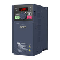
EM730/EM730E-0R7-2B
Sinee EM730/EM730E-0R7-2B Manuals
Manuals and User Guides for Sinee EM730/EM730E-0R7-2B. We have
1
Sinee EM730/EM730E-0R7-2B manual available for free PDF download: User Manual
Sinee EM730/EM730E-0R7-2B User Manual (346 pages)
Brand:
Sinee
| Category:
Inverter
| Size: 10 MB
Table of Contents
Preface
1
Safety Precautions
2
During Wiring
3
Before Power-On
4
After Power-On
4
During Operation
5
During Maintenance
5
Motor Insulation Inspection
5
Thermal Protection of Motor
5
Precautions
5
Operation above Power Frequency
6
Use Beyond Rated Voltage
6
Altitude and Derating
6
Precautions for Scrapping of Inverter
6
Table of Contents
7
Chapter 1 Overview
10
Model and Specification of EM730/EM730E Series Inverter
10
Working Status of Inverter
13
Detailed Introduction to Running Status of EM730/EM730E Series Inverter
13
Running Mode of Inverter
14
Set Mode of Inverter
14
Schematic Diagram of Speed Input Mode
15
Schematic Diagram of Setting of Main Frequency Source a
15
Schematic Diagram of Setting of Auxiliary Frequency Source B
16
Schematic Diagram of Setting of Main and Auxiliary Operations
16
Operation Method of Inverter
17
Schematic Diagram of Torque Input Mode
17
Control Logic Diagram of Terminal Operation
18
Product Check
19
Chapter 2 Installation
19
Outline Dimensions and Installation Dimensions
20
Product View
21
Outline Dimensions of Inverter and Keyboard
22
Keyboard Appearance
22
Outline and Installation Dimensions
23
Installation Site Requirements and Management
24
Environment Temperature
24
Installation Direction and Space
25
Preventive Measures
25
Connection of Peripheral Device
26
Chapter 3 Wiring
26
Wiring of Main Circuit Terminal
27
Composition of Main Circuit Terminal
27
Schematic Diagram of Terminals
28
Functions of Main Circuit Terminals
30
Standard Wiring Diagram of Main Circuit
31
Input Side Wiring of Main Circuit
31
Installation of Leakage Circuit Breaker
32
Installation of Electromagnetic Contactor
32
Connection with Terminal Block
32
Connection of Input Circuit Breaker
32
Installation of Surge Suppressor
33
Installation of Noise Filter on Power Supply Side
33
Output Side Wiring of Main Circuit
34
Wiring of Inverter and Motor
34
Prohibition of Connection of the Power Cable to Output Terminal
34
Incorrect Installation of Noise Filter
34
Prohibition of Short Circuit or Grounding of Output Terminal
35
Prohibition of Use of Phase-Shifting Capacitor
35
Prohibition of Use of Electromagnetic Switch
35
Installation of Noise Filter on Output Side
35
Solution to Inductive Interference
36
Solution to RF Interference
36
Wiring Distance between Inverter and Motor
36
Cable and Screw Dimensions of Main Circuit
37
Cable Dimensions and Terminal Screw Specifications
37
Ground Wire
38
Wiring of Control Circuit Terminal
39
Installation and Wiring of Braking Resistor and Braking Unit
39
Composition of Control Circuit Terminal
39
Functions and Wiring of Control Circuit Terminals
39
Wiring of Analog Input Terminal
41
Wiring of Multi-Function Input Terminal
42
Wiring Diagram of External Current Source and AI2 Terminal
42
Wiring Diagram of Multi-Function Input Terminals
42
Wiring of Multi-Function Output Terminals
43
Wiring of Analog Output Terminals
43
Wiring of 485 Communication Terminals
44
Communication Terminal Wiring of Single Inverter
44
Wire and Screw Dimensions of Control Circuit
45
Precautions for Control Circuit Wiring
45
Wiring of Communication Terminals of Multiple Inverters
45
Standard Wiring Diagram of Control Circuit
46
Extension Wiring of Keyboard
47
Connection Test
47
Keyboard Operations
48
Keyboard Functions
48
Structure of LED Keyboard
48
Functions of Keys and Indicators on LED Keyboard
48
Chapter 4 KEYBOARD OPERATIONS
48
Operation Mode of Keyboard with Digital Tube Display
49
Full Menu Mode (--A--)
50
Flowchart of Menu Mode Selection
50
Flowchart from Power-On to F03.28=5.28 Setting
51
User-Defined Mode (--U--)
52
Example of User-Defined Mode Setting
52
Non-Default Mode (--C--)
53
Protection Monitoring
54
Operation Monitoring
54
Protection Information Display Mode (--E--)
54
Normal Monitoring
54
Run/Stop
55
Editing Status in the Monitoring Mode
55
Other Warning Prompts
56
P.-ON Prompt
56
P.-OFF Prompt
56
SOFT.E Warning
56
Inverter Commissioning Process
57
Chapter 5 Trial Run
57
Confirmation before Power-On
58
Inverter Status Confirmation after Power-On
58
Precautions for Application Macro Setting
58
Start and Stop Control
59
Terminal Control of Start and Stop
60
Common Process Parameters of Inverter
62
Motor Parameter Identification
63
Introduction to Function Code Groups
64
Chapter 6 Function Code Table
64
Description of Function Code Table
64
Table of Functional Parameters
66
Basic Function Parameter Group
66
Parameter Group of Motor 1
69
Output Terminal Function Group
74
Start/Stop Control Parameter Group
77
V/F Control Parameter Group
79
Vector Control Parameter Group
81
Protection Function Setting Group
87
Multi-Segment Speed and Simple PLC
89
PID Function Group
94
Communication Function Group
98
User-Selected Parameter Group
99
Keyboard and Display Function Group
101
Torque Control Parameter Group
104
Parameter Group of Motor 2
106
Auxiliary Function Group
113
Customization Function Group
116
Virtual I/O Function Group
117
Monitoring Parameter Group
120
Protection Record Group
123
Winding/Unwinding Application Macro Parameter Group
125
Basic Function Parameter Group of F00 Group
129
Chapter 7 Function Code Details
129
Detailed Setting of Main Frequency Source a
135
Frequency Source Setting Control (Gain Description)
140
Acceleration and Deceleration Time
141
Schematic Diagram of Duration of Forward/Reverse Dead Zone
144
Relation Betw. Rated Power and Carrier Frequency Setting of Inverter
145
Details of Motor Parameter Group Options
146
Motor 1 Parameter Group of F01 Group
147
Steady-State Equivalent Model of Asynchronous Motor
149
Function Parameter Group of Input Terminal of F02 Group
152
Function List of Multi-Function Digital Input Terminals
153
Schematic Diagram of Positive/Negative Logic Sampling of Terminal
160
Function Code Details of Bit Operation
160
Schematic Diagram of Terminal Filter Sampling
161
Schematic Diagram of Terminal Delay Sampling
162
Function Parameter Group of Output Terminal of F03 Group
166
Function List of Multi-Function Digital Output Terminals
166
Diagram of Level and Single Pulse Output of Digital Output Terminal
174
Function List of Multi-Function Analog Output Terminal
175
Start/Stop Control Parameter Group of F04 Group
177
Acceleration/Deceleration Time Control Diagram
182
Flux Braking Gain
184
Start Mode after Protection/Free Stop
184
DC Braking Process for Start
184
DC Braking Process for Stop
184
VF Control Parameter Group of F05 Group
185
Schematic Diagram of Multi-Point Polyline V/F Curve
188
Rise Time Description of VF Separation Voltage
190
Vector Control Parameter Group of F06 Group
191
Schematic Diagram of PI Parameters
193
Schematic Diagram of High Frequency Injection
198
F07 Protection Parameter Group
199
Detailed Definition of Protection Shield Bits
200
Schematic Diagram of Overvoltage Stall Protection
202
Schematic Diagram of Instantaneous Stop/Non-Stop Deceleration Function
203
Detailed Definition of Protection Action Bits
206
Multi-Segment Speed and Simple PLC Parameter Group of F08 Group
207
Details of PLC Running Mode
210
Schematic Diagram of Simple PLC Operation
210
PID Function Parameter Group of F09 Group
217
Description of PID Positive/Negative Action
220
Description of PID Parameter Options
222
Diagram of Automatic Switching of PID Parameters Based on Deviation
223
Description of Sleep/Wake-Up Function
227
Details of Multi-Segment PID Setting Function
229
Communication Function Parameter Group of F10 Group
231
Schematic Diagram of Communication Timeout
233
Timing Parse Diagram of Complete Data Frame
234
User-Selected Parameter Group of F11 Group
236
Keyboard and Display Function Parameter Group of F12 Group
238
List of Function Codes with Reference Input Properties
239
Torque Control Parameter Group of F13 Group
245
Details of Final Control Mode of Inverter
245
Parameter Group of Motor 2 of F14 Group
250
Auxiliary Function Parameter Group of F15 Group
253
Schematic Diagram of Jog Running
254
Details of Jog Running Command
254
Schematic Diagram of Acceleration and Deceleration Time
255
Diagram of Automatic Switching of Acceleration and Deceleration Time
257
Schematic Diagram of FAR Detection
259
Schematic Diagram of FDT Detection
260
Schematic Diagram of ADT Detection
261
Schematic Diagram of Energy Consumption Braking
262
Details of Fan Operation
263
F16 Customized Function Parameter Group
265
Block Diagram of Fixed-Length Counting
267
Example of Fixed-Length Counting
268
Block Diagram of Counting Function
269
Virtual I/O Function Parameter Group of F17 Group
271
Virtual I/O Function Parameter Group of F17 Group
272
Monitoring Parameter Group of F18 Group
276
F19 Protection Record Parameter Group
279
F27 Winding and Unwinding Application Macro Parameter Group
282
Feedforward Parameters and Other Settings
288
Wiring Diagram of Double-Frequency Wire Drawing Machine
289
Chapter 8 Motor Parameter Self-Identification
298
Precautions before Self-Identification
299
Self-Identification Steps
300
Protection Content
301
Chapter 9 Protection/Warning Solutions
301
The Prompt Codes and Description of Inverter Operation
305
Protection Analysis
306
Failure in Parameter Setting of Function Codes
306
Abnormality of Motor Rotation
306
Too Long Acceleration Time of Motor
307
Too Long Deceleration Time of Motor
307
Electromagnetic Interference and RF Interference
307
Action of Leakage Circuit Breaker
308
Mechanical Vibration
308
Motor Rotation in the Absence of Inverter Output
309
Inconsistency between Output Frequency and Set Frequency
309
Daily Maintenance of Inverter
310
Content of Regular Inspection
311
Replacement Intervals of Inverter Components
311
Instructions for Inverter Warranty
311
Braking Resistor
313
Chapter 10 Select Accessories
313
Braking Unit
314
Selection of Connecting Wires
315
Wire Specifications of Braking Units and Braking Resistors
315
Wi-Fi Module
316
Interface Mode (MODBUS)
317
Protocol Format (MODBUS)
317
Message Format (MODBUS)
317
Chapter 11 MODBUS Communication Protocol
317
Applicable Scope
317
Address Code
318
Function Code
318
Schematic Diagram of Message Frame in RTU Mode
318
0X42: Function Code Used to Write Multiple Registers or Commands
322
0X08: Function Code for Diagnosis
324
0X06: Function Code Used to Write a Single Register or Command
325
0X10: Function Code Used to Write Multiple Registers or Commands
327
Register Address Distribution
328
Detailed Definition of Register Address of MODBUS Protocol
328
Definition of Frame Data Length
333
Exception Response
338
Definitions of Exception Codes
338
Protocol Description
339
Definition of Inter-Frame and Intra-Frame Time Interval
339
Data Frame Processing
340
Correspondence between Time Interval and Baud Rate (T Adjust = 1Ms)
340
Schematic Diagram of Normal and Exceptional Data Frames
340
Response Delay
341
Communication Timeout
341
Examples
342
Advertisement
Advertisement
Related Products
Sinee EM730/EM730E-0R4-2B
Sinee EM730/EM730E-1R5-2B
Sinee EM730/EM730E-2R2-2B
Sinee EM730/EM730E-0R7-3B
Sinee EM730/EM730E-1R5-3B
Sinee EM730/EM730E-2R2-3B
Sinee EM730/EM730E-4R0-3B
Sinee EM730/EM730E-5R5-3B
Sinee EM730/EM730E-7R5-3B
Sinee EM730/EM730E-011-3B
Sinee Categories
Inverter
Servo Drives
DC Drives
More Sinee Manuals
Login
Sign In
OR
Sign in with Facebook
Sign in with Google
Upload manual
Upload from disk
Upload from URL