Table of Contents
Advertisement
User Manual
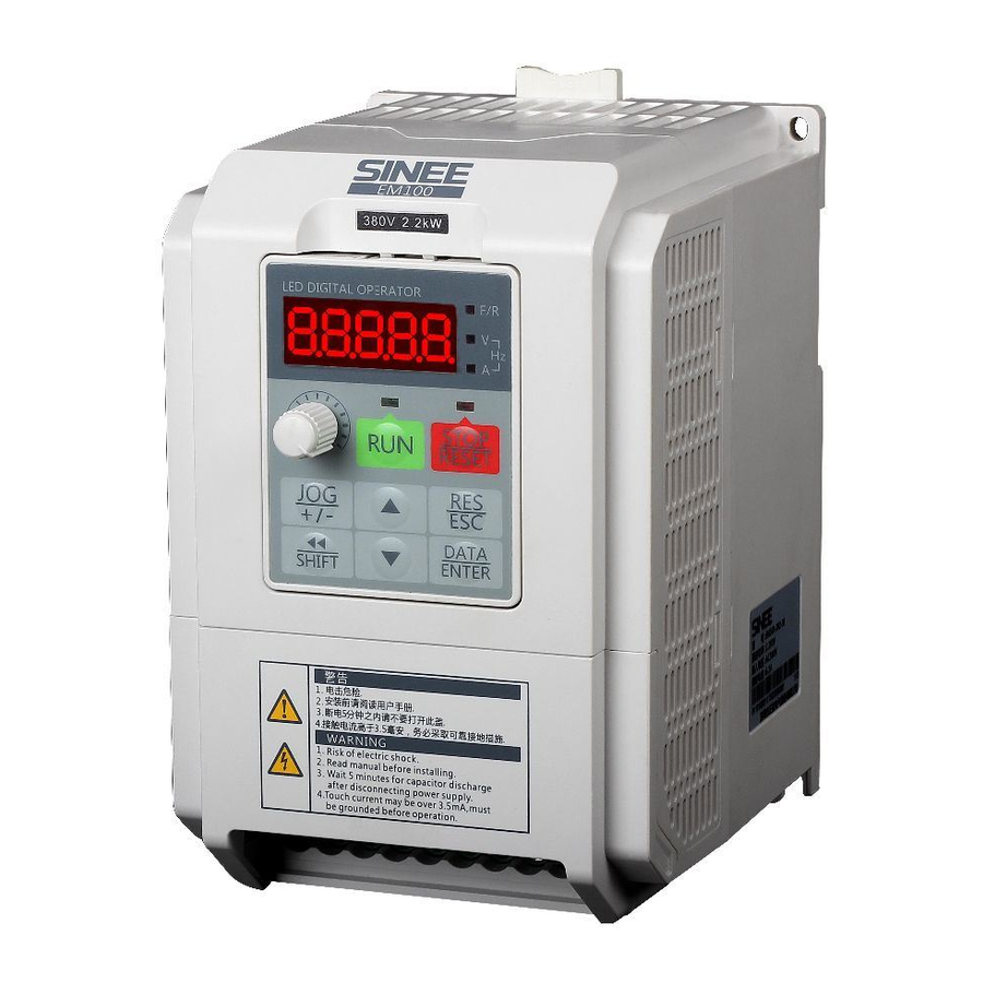
EM100 Mini Inverter
Preface
Thank you for purchasing EM100 series mini inverter.
Document No.: 31010008
Version No.:103
Issue Date: 06/03/2013
EM100 mini inverter is a compact, intuitive, reliable and performing AC variable speed
drive for 3-phase induction motors.
This manual offers the general information of installation, wiring, function parameters,
daily maintenance, and fault diagnosis of EM100 mini inverter.
It is the duty of any user to perform the appropriate, correct installation or configuration
of the optional parameters of the devices. Neither SINEE nor its distributors shall be
responsible or liable for misuse of the information contained herein or mismatching the
inverter with the motor.
In the interests of commitment to a policy of continuous development and improvement,
SINEE reserves the right to update the specification of the product or its performance, or
the content herein without notice.
More updates and information are available at www.sinee.cn.
1
Advertisement
Table of Contents
Troubleshooting

Related Manuals for Sinee EM100-0R4-1B


Summary of Contents for Sinee EM100-0R4-1B
- Page 1 In the interests of commitment to a policy of continuous development and improvement, SINEE reserves the right to update the specification of the product or its performance, or the content herein without notice. More updates and information are available at www.sinee.cn.
-
Page 2: Table Of Contents
User Manual EM100 Mini Inverter CONTENTS 1. SAFETY INFORMATION ..................3 1.1SAFETY P .................... 3 RECAUTIONS 1.2 P ......................6 RECUATIONS 2. OVERVIEW ........................7 2.1 V ....................7 ERIFYING RODUCT 2.2 M ............. 7 ODEL UMBERING CHEME AND AMEPLATE 2.3 M ...................... - Page 3 User Manual EM100 Mini Inve erter 1. Safety In nformation Danger: The addition of this symbol to a Danger or Warn ning safety abel indicates that an electri ical hazard exists, which wi ill result in ersonal injury if the instructio ons are not followed.
- Page 4 User Manual EM100 Mini Inve erter Wiring: Danger 1. Wiring m must be performed by authorize ed and qualified personnel. Ri isk of danger. 2. Circuit-br reaker should be installed betw ween inverter and the mains. R Risk of fire. 3....
- Page 5 User Manual EM100 Mini Inve erter After Power-on Danger Do not to uch the inverter and its periph heral circuits with wet hands. Rick of electrical hazard. Do not to uch any input/output terminal ls of inverter with bare hands. .
- Page 6 Altitude Derating In altitudes above 1000m above sea level, the derating is required because of poor cooling effect due to rare air. Contact SINEE for technical support. Cautions for Inverter Disposal The electrolytic capacitors on the main circuit and PCBA may explode when they are burnt.
-
Page 7: P Roduct
User Manual EM100 Mini Inve erter 2. Ove rview 2.1 Verifying Pro oduct Caution Never install an inverter that is damaged o r missing components. Otherw wise, a risk of injury. Refer to the follow wing table, and check and ver rify the product. - Page 8 User Manual EM100 Mini Inverter 2.3 Model Number List Table 2-1 EM100 Model Number List Rated Input Motor Rated Output Model No. Voltage Power(kW) Current(A) EM100-0R4-1B EM100-0R7-1B 0.75 1-phase AC220V EM100-1R5-1B EM100-2R2-1B 10.0 EM100-0R7-3B 0.75 EM100-1R5-3B EM100-2R2-3B EM100-4R0-3B 3-phase AC380V/415V...
- Page 9 User Manual EM100 Mini Inverter Governor Deflection 1:50 Speed Control 1.0% Accuracy Acceleration/ 0.01~600.00 seconds Deceleration Time Rated output voltage: 5%~100% adjustable V/F Features Frequency base:20.00~320.00Hz adjustable Automatic torque boost, fixed torque boost Torque Boost curve, customer defined V/F curve scaling Start Torque 150%/1Hz AVR is active while output voltage remains...
- Page 10 User Manual EM100 Mini Inverter 20mA or a voltage input:0~10V Input impedance: voltage input: 1MΩ, current input: 250Ω Accuracy: 0.2% 1 programmable OC output Max. load capacity: 50mA/24V Output frequency range:0~1kHz Numeric Output 1 programmable relay output, EA-NO, Terminal EB-NC, EC-Common port Contact capacity: 3A/AC250V Power factor:>0.4 or 1A/DC30V 1 programmable analog output terminal,...
- Page 11 User Manual EM100 Mini Inve erter 2.5 EM100 Outlo DIN Rail Release B Button Housing g Upper Main Air Out tlet Housin Keypa Air Outle Termi inal Cover Namepla Power Contro ol Terminal Main Air Inl Terminal EM100 0 ID...
- Page 12 User Manual EM100 Mini Inverter 2.6 Overall and Installation Dimensions 2.6.1 Overall Dimensions Model EM100-0R4-1B EM100-1R5-1B EM100-5R5-3B EM100-015-3B EM100-0R7-1B EM100-2R2-1B EM100-7R5-3B EM100-0R7-3B EM100-011-3B EM100-1R5-3B Unit EM100-2R2-3B (mm) EM100-4R0-3B 289.5 130.5 140.5 110.5 121.5 152.5 165.2 185.7 104.7 N.W./Kg Frame SIZE1...
- Page 13 User Manual EM100 Mini Inverter 2.6.3 Keypad Dimensions 2.6.4 Dimensions of Keypad Chassis (Accessories) and Mounting Holes Remarks: Please contact distributors or SINEE for keypad chassis if needed.
-
Page 14: Installation
User Manual EM100 Mini Inve erter 3. Insta allation 3.1 Mechanical I Installation 3.1.1 Installation n Recommendations Caution Always ho old the case when carrying t the inverter. Risk of in njury if only holding the termi nal cover. Installatio on base shall be metal or oth her non-flammable material Risk of fir... - Page 15 User Manual EM100 Mini Inverter 3.1.4.1 Installation Space of Single EM100 3.1.4.2 Vertical Installation of Multi-EM100...
- Page 16 User Manual EM100 Mini Inverter 3.1.4.3 Table of Heat Dissipating Capacity (HDC), Mass Airflow(MAF) and Noise of Single EM100 Noise Model No. Frame /h) (CFM) (m (W) (dB/A) EM100-0R4-1B 13.6 SIZE1 EM100-0R7-1B 13.6 EM100-1R5-1B EM100-2R2-1B EM100-0R7-3B SIZE2 EM100-1R5-3B EM100-2R2-3B EM100-4R0-3B EM100-5R5-3B 31.2...
- Page 17 User Manual EM100 Mini Inverter 3.1.5 Installing with Screws a. 4-hole Installation See Overall and Installation Dimensions for the dimensions of 4-hole (Hole a). Refer to Figure a, and punch 4 holes on the installation panel. Put the inverter against the panel and mate 4 holes, and then tighten screws in the 4 holes (Tighten any of the 2 screws in diagonal position, tighten 4 holes with screws for strengthened installation.
- Page 18 User Manual EM100 Mini Inverter b. 3-hole Installation See Overall and Installation Dimensions for the dimensions of 3-hole (Hole b). Refer to Figure b, and punch 3 holes on the installation panel with screws in each of them. Do not tighten the screws, leave a distance of 7.5~9mm between the gaskets and installation panel, hung the inverter onto the 3 screws from top to bottom (Screw size: M4xL, L>16mm, tightening torque: 1N.m±10%), and then tighten the 2 screws at the bottom.
- Page 19 User Manual EM100 Mini Inverter Remarks: Instruction of assembling the flange: Assemble the flange left and right on the left and right sides of EM100 first, fasten the screws on the top and at the buttom, locate the inverter with flange into the mounting hole, and tighten the screws to finish the assembly.
- Page 20 User Manual EM100 Mini Inverter 3.1.8 Disassembly and Assembly of Keypad a. Disassemble keypad. See following Figure: Push the buckle on the keypad in Direction 1 first, and then lift up the keypad in Direction 2. b. Assemble keypad. See following Figure: Place keypad in the slot in Direction 1, and then press the keypad in Direction 2 until it clicks into right place.
- Page 21 User Manual EM100 Mini Inverter 3.1.9 Disassembly and Assembly of Terminal Cover a. Disassemble terminal cover: remove terminal cover in the direction as shown in the Figure below. b. Assemble keypad. See following Figure: Place the upper buckle of the terminal cover in the slot of upper housing in Direction 1, and then press the two lower buckle of terminal cover in Direction 2 until it clicks into right place of upper housing.
- Page 22 User Manual EM100 Mini Inverter 3.1.10 Mounting Keypad a. Surface mounting: Punch 4 holes (3.5±0.4mm) as per the overall dimensions of keypad, tighten the keypad on the installation panel with M3 tapping screw (For plastic materials, tightening torque: 0.5N.m±10%, the maximum tightening depth in keypad: 11±1mm) b.
- Page 23 User Manual EM100 Mini Inve erter 3.2 Wiring Open the termina al cover, check the terminal bl ock, main circuit and control circuit terminals. Considerations fo or wiring: Main circuit terminals R/L1, S/L2, and T/ /L3 are input terminals. Misco onnection will result in inve erter damage.
- Page 24 User Manual EM100 Mini Inverter 3.2.1 Connection to Peripherals Figure 3-1 Connections between EM100 and Its Peripherals...
- Page 25 User Manual EM100 Mini Inverter 3.2.2 Wiring Main Circuit and Control Circuit Figure 3-2 Wiring Main Circuit and Control Circuit Remarks: refers to main circuit terminals. refers to control circuit terminals. 2. User selects braking resistor based on real needs. 3.
- Page 26 User Manual EM100 Mini Inve erter 3.2.3 Function of f Main Circuit Dange 1. Wiring only after the power supply is OFF F.Risk of electric shock. 2. Only profess sionals shall conduct wiring.R Risk of devices damage or pers sonal injury. 3.
- Page 27 User Manual EM100 Mini Inverter 3.2.4 Standard Wiring of Main Circuit R/L 1 S/L 2 T/L 3 Figure 3-5 Standard Wiring of EM100 Main Circuit 3.2.5 Wiring Main Circuit on Input Side Installing a Circuit Breaker Install an air circuit breaker (MCCB) between the power supply and input terminals. Choose a MCCB with a capacity of 1.5-2 times of inverter rated current.
- Page 28 User Manual EM100 Mini Inverter Installing an AC Reactor If power supply is connected to capacitive load, an excessive big surge current will occur and rectifier of inverter can be broken down. Install an optional 3-phase/1-phase AC reactor on input side of inverter to suppress peak current and voltage, and improve power factor of the system.
- Page 29 User Manual EM100 Mini Inverter 3.2.6 Wiring the Output Side of Main Circuit Connecting the Inverter to Motor Connect inverter output terminals U, V, and W to motor input terminals U, V and W. Check that the motor forwards with the Forward Command. Switch any 2 of the inverter output terminals U, V, or W to each other and reconnect if the motor reverses.
- Page 30 User Manual EM100 Mini Inverter Countermeasures Against Inductive Interference As stated previously, except installing a noise filter, all output cables can be routed through a grounded metal pipe to prevent inductive interference on the output side. The distance between output cables and signal line should > 30cm, and the inductive interference will be reduced considerably, as shown in Figure 3-10.
- Page 31 Tightening Model No. of Cable Size Terminal Screw Torque Inverter Type (N.m) ( (mm ) EM100-0R4-1B L1 L2 U V W M3 1.0~1.2 EM100-0R7-1B L1 L2 U V W M3 1.0~1.2 300V EM100-1R5-1B U V W M3 1.0~1.2 R/L1 S/L2...
- Page 32 User Manual EM100 Mini Inverter 3.2.9 Wiring Braking Resistor Install a braking resistor in EM100 for quick brake of motor, and set the corresponding function code of inverter as dynamic braking active. Connect braking resistor to terminal +, PB, do not connect to other terminals.
- Page 33 User Manual EM100 Mini Inverter Analog 0/2~10V, input impedance: 1MΩ voltage input Max. input voltage:15V Common port Input/output signal common port IS can be configurated as current Analog input or voltage input and switched current /voltage by S2. Input range:0/4~20mA or input 0/2~10V 0~10V, output accuracy: ±2%,...
- Page 34 User Manual EM100 Mini Inverter 3.2.10.3 Wiring the Analog Input Terminals See Figure 3-15 for wiring terminals VS via analog voltage signal: When analog voltage input signal is as the external power supply, see Figure 3-15-a for wiring terminal VS. When analog voltage input signal is as the potentiometer, wire terminal VS as shown in Figure 3-15-b.
- Page 35 User Manual EM100 Mini Inverter 3.2.10.6 Wiring Communication Terminal 1. Refer to the Figure 3-19 for connecting single inverter to PC/PLC: Figure 3-19 RS485 and Single Inverter Connection 2. Refer to the Figure below for connecting multi-inverter to PC/PLC: When PLC communicates with multi-inverter, connect the RS485 Communication interface A+ of inverters to A+,A- to A-.
- Page 36 User Manual EM100 Mini Inverter 3.2.10.7 Size of Control Circuit Cable and Screw To lower interference and attenuation of control signal, the cable length of control signal should be in a maximum of 50m, and the distance should be in a minimum of 30cm between the signal cable and the power cable.
- Page 37 User Manual EM100 Mini Inverter Figure 3-22 Disassembling the Keypad and Connecting Extension Keypad Wire 3.2.10.9 Wiring Check Perform the following checks after completing wiring: If wiring is correct. If anything is left in inverter like screw, or wire clippings. If the screw is loose.
-
Page 38: Keypad Operation
User Manual EM100 Mini Inverter 4. Keypad Operation 4.1 Keypad EM100 keypad consists of LED display, keys, and potentiometer. See Figure 4-1. User can perform function setting, status monitoring, fault monitoring, start/stop control, and jog operation for EM100 through keypad. LED Display Potentiometer Keys... -
Page 39: Method
User Manual EM100 Mini Inverter Select function code, menu or reduce the setting DOWN value of parameter. RUN: Green On: the inverter is running. Flashing: the inverter is stopping. STOP: Red On: the inverter fails. F/R: Red Off: Forward Status Indicator On: Reverse A:Red Present display data unit is A. - Page 40 User Manual EM100 Mini Inverter Figure 4-2 Main Menu Selection 4.2.2 Sub-menu Selection Select 1 code in sub-menu selection. For instance, in sub-menu of F01._ _, select any code from F01.00~F01.22. See Figure 4-3 for selecting code. Figure 4-3 Sub-menu Selection 4.2.3 Function Setting Inverter can display, edit, save and reset parameter in function setting status.
- Page 41 User Manual EM100 Mini Inverter If there is an unexpected editing, press , and then LSB (on the right) flashing refers to that the parameter is reset previous value. Press again to return previous menu and do not edit parameter, but press , the edited parameter will be saved.
- Page 42 User Manual EM100 Mini Inverter F00.07 (primary numeric frequency) which will assist user to edit setting frequency. If there is no operation with keypad for 5 seconds, keypad display will return the sub-menu of monitoring code group. Edit setting frequency by press in operation status or stop status.
-
Page 43: Parameter Tables
User Manual EM100 Mini Inverter 5. Parameter Tables 5.1 Format of Parameter Tables 14 groups of parameters of EM100: F00, F01, F02, F03, F04, F05, F06, F07, F08, F09, F10, F11, C00, and E00. F00-F11: function setting codes, C00 group: monitoring codes, and E00 group: fault monitoring codes. - Page 44 User Manual EM100 Mini Inverter F/R-Forward/Reverse 1: RUN-Forward, F/R- Reverse 2: RUN-NO forward, Xi-NC stop, F/R-NO reverse 3: RUN-NO run, Xi-NC stop, F/R- Forward/Reverse 0: Primary numeric frequency setting 1: VP keypad potentiometer Primary Speed F00.03 2: VS analog voltage input 〇...
- Page 45 User Manual EM100 Mini Inverter Auxiliary F00.08 Numeric Frequency 0.00~Fmax 0.00 ● Setting F00.09 Acceleration Time 1 0.01~600.00 15.00 ● F00.10 Deceleration Time1 0.01~600.00 15.00 ● Maximum F00.11 Fmax:20.00~320.00 50.00 〇 Frequency Upper Limit F00.12 Fup: Fdown~Fmax 50.00 〇 Frequency Lower Limit F00.13 Fdown: 0.00~Fup...
- Page 46 User Manual EM100 Mini Inverter F01.04 Motor Rate Speed 1~20000 XXXXX 〇 0: Y Wiring F01.05 Motor Wiring Mode 〇 1: Δ Wiring Motor Rated F01.06 0.70~0.95 〇 Power Factor F01.07 Motor Efficiency 70.00~97.00 XXXXX 〇 Idling Excitation F01.08 0.1~100.0 XXXXX 〇...
- Page 47 User Manual EM100 Mini Inverter 17: Switch run command to terminal 18: Program running reset 19: Switch to auxiliary speed setting 20: External fault input 21: Start wobbulation operation 0:Positive Logic Terminals are on at 0V/off at Multi-function Input F02.06 Positive/Negative 000000 〇...
- Page 48 User Manual EM100 Mini Inverter VS Input Bias 1~ VS Input Bias F02.21 VS Input Bias 2 75.0 ● F02.22 VS Input Bias 3 VS Input Bias 2~100.0 100.0 ● F02.23 IS Output Bias 0 -100.0~100.0 ● F02.24 IS Output Bias 1 -100.0~100.0 25.0 ●...
- Page 49 User Manual EM100 Mini Inverter F04 Group:Start/Stop Control Parameters DC Brake Current F04.00 0.00~150.00 〇 at Start DC Brake Time at F04.01 0.00~30.00 0.00 〇 Start Acceleration/ 0: Linear mode F04.02 Deceleration 〇 1: S curve mode Mode F04.03 S Curve Time 0.00~600.00 0.00 〇...
- Page 50 User Manual EM100 Mini Inverter 0.00~Frequency 2 F05.06 Frequency 1 1.00 ● Fbase=100.0% ● F05.07 Frequency 2 Frequency 1~ Frequency 3 4.00 ● F05.08 Frequency 3 Frequency 2~ Frequency 4 10.00 ● F05.09 Frequency 4 Frequency 3~100.00 16.00 Open Loop Slip ●...
- Page 51 User Manual EM100 Mini Inverter F06.09 Output Voltage 5.00~100.00 100.00 ● 0: Disabled Dynamic Brake 1: Enabled F06.10 〇 Control 2: Enabled at running 3: Enabled at deceleration Dynamic Brake 380V:510~800 F06.11 〇 Voltage 220V:300~400 F06.12 Brake Duty Ratio 5.0~100.00 100.00 〇...
- Page 52 User Manual EM100 Mini Inverter Jump Frequency of F06.23 0.00~Fmax 5.00 ● Wobbulation Rising Time of F06.24 0.00~600.00 15.00 ● Wobbulation Dropping Time of F06.25 0.00~600.00 5.00 ● Wobbulation 0: Run as per lower limit frequency Lower Limit F06.26 1: Run at zero speed when 〇...
- Page 53 User Manual EM100 Mini Inverter Overvoltage Stall 0.00~300.00 F07.08 10.00 ● Mode 2 Integral Time 0.00: Integration Disabled Overheating Prealarm 50~115 F07.09 ℃ 〇 Temperature Motor Overload 0: Prohibited F07.10 〇 Protection Options 1: Permitted Motor Overload F07.11 30~300 〇 Protection Time Ones place: Fault retry times 0: Fault retry prohibited...
- Page 54 User Manual EM100 Mini Inverter F08.01 Preset Speed 2 0.00~Fmax 5.00 ● F08.02 Preset Speed 3 0.00~Fmax 10.00 ● F08.03 Preset Speed 4 0.00~Fmax 15.00 ● F08.04 Preset Speed 5 0.00~Fmax 20.00 ● F08.05 Preset Speed 6 0.00~Fmax 25.00 ● F08.06 Preset Speed 7 0.00~Fmax...
- Page 55 User Manual EM100 Mini Inverter Program F08.14 Operation Time 0~60000 ● Program F08.15 Operation Time 0~60000 ● Speed Cycling F08.16 1~60000 ● Times F09 Group: PID Parameters 0: Numeric PID setting PID Reference 1: Terminal VS F09.00 〇 2: Terminal IS Setting Mode 3: Terminal VP F09.01...
- Page 56 User Manual EM100 Mini Inverter 0:4800 1:9600 F10.01 Communication Bit Rate bps 1 〇 2:19200 3:38400 0:No parity 1+8+1 F10.02 Communication Format 1:Even parity 1+8+1+1 〇 2:Odd parity 1+8+1+1 0.0~60.0 F10.03 Communication Overtime 0.0: Communication 〇 overtime disabled Master-slave 0:The inverter is the slave F10.04 〇...
- Page 57 User Manual EM100 Mini Inverter Inverter Rated F11.04 60~480 × Voltage Inverter Rated F11.05 0.1~100.0 XXXXX × Current Inverter Running F11.06 0~65535 User Monitoring HOUR XXXXX × Time Inverter Running F11.07 0~60 User Monitoring XXXXX × Time Running Time 0: Disabled F11.08 〇...
- Page 58 User Manual EM100 Mini Inverter Output Terminal * * * * * * R1 Y1(Monitoring C00.13 × Status output terminal logic status) VS Input C00.14 0.00~10.00 × Monitoring IS Input C00.15 0.00~20.00 × Monitoring Inverter Heatsink C00.16 0~200 × Temperature C00.17 VP Input Monitoring 0~5.00...
-
Page 59: Parameter Description
User Manual EM100 Mini Inverter 6. Parameter Description F00 Group: General Parameters Function Range Unit Default Type Speed Reference Input Frequency 0.00~ F00.00 XXXXX Monitoring Fmax F00.00 is only for reference. Its parameters are present frequency setting values. Symbol “-” will not be displayed if the value is negative, but user can check it via keypad indicator. - Page 60 User Manual EM100 Mini Inverter indicator on is on which refers to that inverter is in operation status, flashing refers to that inverter is in ramp-to-stop status. F00.02 Ones Place=1 Terminal control Control command given by multi-function input terminals RUN, F/R, FJOG, and RJOG. See the description of F00.02 tens place for detailed control logic.
- Page 61 User Manual EM100 Mini Inverter F00.02 start/stop selected as 2-wire sequence terminal control (F00.02=01or F00.02=11), when terminal RUN or F/R is on, inverter stops with PLC section cycling stop command. Even control terminal RUN or F/R is on, the inverter will not run after stop command cancelled.
- Page 62 User Manual EM100 Mini Inverter Running Direction Forward Reverse SB1: Key for run K1: Key for stop Figure 6-4 3-wire Terminal Control Mode 2 When inverter is in speed setting mode, it can be set by numeric setting, analog voltage, and analog current.
- Page 63 User Manual EM100 Mini Inverter F00.04=0 Auxiliary numeric frequency setting mode, defined by F00.08 parameters. F00.04=1 VP keypad potentiometer defines the setting frequency. F00.04=2 Analog terminal VS voltage defines the setting frequency. F00.04=3 Analog terminal IS current defines the setting frequency. F00.04=4~9 Not used F00.04=10 Process PID setting frequency defines the setting frequency.
- Page 64 User Manual EM100 Mini Inverter Function Range Unit Default Type Primary Numeric F00.07 0.00~ Fmax 0.00 ● Frequency Setting Auxiliary Numeric 0.00 ● F00.08 0.00~ Fmax Frequency Setting F00.07 Operation frequency primary numeric setting value. The parameter range: 0.00~Fmax upper limit frequency. F00.08 Operation frequency auxiliary numeric setting value.
- Page 65 User Manual EM100 Mini Inverter EM100 Speed Setting Input Modes Figure 6-6 Speed Setting Input Mode...
- Page 66 User Manual EM100 Mini Inverter Function Range Unit Default Type Maximum Frequency 50.00 F00.11 Fmax:20.00~320.00 〇 Upper Limit Frequency 50.00 F00.12 Fup:Fdown~Fmax 〇 Lower Limit Frequency 0.00 F00.13 Fdown:0.00~Fup 〇 F00.11 The maximum frequency (Fmax) can be set, and its range: 20.00~320.00Hz. F00.12 The upper limit frequency (Fup) can be run after inverter starts, Fup range: Fdown~ Fmax.
- Page 67 User Manual EM100 Mini Inverter Figure 6-7 Forward/Reverse Deadband Function Range Unit Default Type F00.17 Carrier Frequency 2.000~12.000 4.000 ● 0: Fixed carrier 1: Random carrier 2: Fixed carrier, which can be adjusted by carrier temperature and F00.18 Random Carrier Mode ●...
- Page 68 User Manual EM100 Mini Inverter Function Range Unit Default Type 0: Do not save the frequency Saving Setting before power loss F00.21 〇 Frequency Options 1: Save the frequency before power loss 0: Disabled F00.22 Default Reset 〇 1: Reset default Saving Setting Frequency Options F00.21=0 Do not save the frequency before power loss F00.21=1 Save the frequency before power loss...
- Page 69 User Manual EM100 Mini Inverter User cannot know motor parameters F01.08~F01.12, please obtain these parameters by autotuning. Before autotuning motor parameters, inverter will set motor nameplate parameters (Set by F01.00~F01.07) as the standard motor parameters automatically. See Figure 6-8 for the T equivalent model of the motor.
- Page 70 User Manual EM100 Mini Inverter Multi-function Input X4-D2 F02.03 〇 F02.04 Multi-function Input X5-D3 〇 F02.05 Multi-function Input X6-FRS 〇 Table 6-6 Function of Multi-function Input Terminals Setting Function Description Value No function To block terminal if terminal hardware failure occurs. If start/stop control mode is in terminal control mode (F00.02=1~4), and if the terminal is on, the inverter will RUN -run...
- Page 71 User Manual EM100 Mini Inverter If acceleration/deceleration prohibition terminal is on, it is Acceleration/ prohibited performing acceleration/deceleration command. Deceleration The inverter will keep output frequency unchanged, and Prohibition will not be controlled by input frequency. 3-wire Sequence Run/Stop It is the NC stop key for 3-wire sequence terminal control. Control(Pulse Stop) When inverter is in the process of ramp-to-stop, and...
- Page 72 User Manual EM100 Mini Inverter 1. Start/Stop of preset speed running is defined by F00.02. 2. When multi-function input terminal setting value is 6, acceleration/deceleration time of preset speed running is controlled and selected by the terminal. 3. Preset speed running will be affected by whether terminal F/R or RUN is ON (in terminal start/stop control mode).
- Page 73 User Manual EM100 Mini Inverter Generally, parameters of F02.07 rarely need adjustment. If adjustment is needed, note the correlation between the filter time and terminal active time to avoid interferences due to less filter times, or slow response and missing command due to more filter times. F02.08 /F02.09 X1/X2 Input Delay Time Refer to set the time how long the inverter delays to respond after the arrival of external signals.
- Page 74 User Manual EM100 Mini Inverter F02.18 VS Output Bias 3 -100.0~100.0 100.0 ● VS Input Bias 0 0.0~VS Input Bias 1 ● F02.19 VS Input Bias 0~ VS VS Input Bias 1 25.0 ● F02.20 Input Bias 2 VS Input Bias 1~ VS F02.21 VS Input Bias 2 75.0...
- Page 75 User Manual EM100 Mini Inverter 2. Diagram of output bias See Figure 6-10-1 and Figure 6-10-2 for input/output bias of Table 6-8-1 and Table 6-8-2 respectively. Figure 6-10-1 Input/Output Bias 1 Figure 6-10-2 Input/Output Bias 2 F03 Group: Output Terminal Parameters Function Range Unit Default Type...
- Page 76 User Manual EM100 Mini Inverter EM100 provides 2 programmable numeric output terminals: 1 multi-function output terminal and 1 relay output terminal. 0~8 programming codes are available, user can define the output quantity of output terminals. 0: Inverter is running: When the inverter is running, Y1 or R1 is on. 1: Frequency reach signal (FAR): When the deviation between the output frequency and setting frequency of inverter in the frequency reaching detection range, Y1 or R1 is on.
- Page 77 User Manual EM100 Mini Inverter Analog output sets upper limit and lower limit to meet various needs. M0 Output Percentage= M0 Lower Limit + M0 Input Percentage * M0 Output Gain* (M0 Upper Limit - M0 Lower Limit). Figure 6-11 M0 Output Percentage Curves 4 curves obtained by set relevant M0 output parameters as shown in Figure 6-11: Curve 1: Set as per the default.
- Page 78 User Manual EM100 Mini Inverter Function Range Unit Default Type Acceleration/ 0:Linear mode F04.02 〇 Deceleration Mode 1:S curve mode F04.03 S Curve Time 0.00~600.00 0.00 〇 Not Used F04.04 Linear Acceleration/Deceleration F04.02=0 Acceleration/Deceleration is in linear mode. S Curve Acceleration/Deceleration F04.02=1 Acceleration/Deceleration is in S curve mode.
- Page 79 User Manual EM100 Mini Inverter Function Range Unit Default Type DC Brake Start Frequency at F04.06 0.10~60.00 2.00 〇 Stop F04.07 DC Brake Current at Stop 0.00~150.00 2.00 〇 DC Brake Waiting Time 0.00 F04.08 0.00~30.00 〇 DC Brake Time at Stop 0.00 F04.09 0.00~30.00...
- Page 80 User Manual EM100 Mini Inverter Description: F05.00=0 Automatic torque boost F05.00=1~10 Fixed torque boost curve F05.00=11~20 Oil pump motor boost curve F05.00=21~30 Synchronous motor boost curve F05.00=31~34 Blower/water pump boost curve F05.00=35 Customer defined V/F curve scaling Figure 6-15 V/F Curves F05.00≠35 Select a fixed V/F boost curve, the output of Ue is corresponding to the setting value of F05.01.
- Page 81 User Manual EM100 Mini Inverter Function Range Unit Default Type Oscillation Suppression 0.00 ● F05.13 0.00~100.00 If output current is not stable, oscillation suppression is applied to limit current oscillation and to avoid overcurrent triggered by current oscillation when motor starts. It is also used to reduce vibration of motor and mechanical devices.
- Page 82 User Manual EM100 Mini Inverter Function Range Unit Default Type UP/DOWN 0.00~100.00 Unit: Hz/ 200mS F06.05 1.00 ● Frequency Rate 0.00(Autorate integration) In primary speed setting mode, edit primary speed setting (F00.07) via multi-function terminal UP/DOWN. Unit: Hz/200mS F06.05=0.00: In autorate integration mode, edit F00.07 value slowly at beginning and then faster later based on the lasting time when terminal UP/DOWN is on.
- Page 83 User Manual EM100 Mini Inverter Function Range Unit Default Type 0: Disabled Dynamic Brake 1: Enabled F06.10 〇 Control 2: Enabled at running 3: Enabled at deceleration 380V:510~800 Dynamic Brake F06.11 〇 Voltage 220V:300~400 Brake Duty 100.00 F06.12 5.0~100.00 〇 Ratio F06.10 sets the enabling range of dynamic brake.
- Page 84 User Manual EM100 Mini Inverter F06.16=2 Enabled in keypad start/stop mode, external fault trips in other modes. Function Range Unit Default Type F06.17 Customer Defined Scaling 0.01~200.00 30.00 ● F06.17 Customer Defined Scaling: Mechanical speed= Customer defined scaling (Mechanical speed coefficient) *Output frequency. Adjust the scaling to match the display speed value with the actual speed.
- Page 85 User Manual EM100 Mini Inverter F06.18 Ones place=1 Terminal control Wobbulation operation is started by function input terminal when the preset wobbulation time is up. If selecting terminal control mode, set any terminal among X1~X6=21. Wobbulation Input Mode F06.18 Tens place=0 Wobbulation operation starts after reaching middle frequency. Middle frequency = (Wobbulation upper limit frequency+ Wobbulation lower limit frequency) /2.
- Page 86 User Manual EM100 Mini Inverter F06.26=0 If output frequency of inverter < Lower limit frequency, inverter will always run as per lower limit frequency. F00.13 defines the lower limit frequency. F06.26=1 If output frequency of inverter < Lower limit frequency, inverter runs as per lower limit frequency first, and runs in zero speed after lower limit frequency running time reached setting value of F06.27.
- Page 87 User Manual EM100 Mini Inverter 0.00~300.00 Current Limit Mode 10.00 ● F07.04 0.00 Integration 2 Integral Time Disabled F07.00=0 Current Limit Control Disabled F07.00=1 Current Limit Mode 1 During acceleration and deceleration, if output current exceeds current limit (F07.01), inverter stops acceleration/deceleration and remains at present running frequency, and will accelerate/decelerate as per previous acceleration/deceleration time after output current decreased.
- Page 88 User Manual EM100 Mini Inverter 2: Overvoltage stall mode 2 380V: 640~800 Overvoltage Stall F07.06 〇 Voltage 220V: 370~400 Overvoltage Stall F07.07 Mode 2 Proportion 0.01~10.00 0.30 ● Gain Overvoltage Stall 0.00~300.00 Mode 2 Integral ● F07.08 10.00 0.00: Integration Disabled Time F07.05=0 Overvoltage Stall Disabled.
- Page 89 User Manual EM100 Mini Inverter F07.10=0 No overload protection for motor, motor is in danger of overheating damage. A relay for overheating protection is suggested to be installed between motor and inverter. F07.10=1 Inverter will judge whether motor is overloaded or not based on the inverse curve of motor overload protection.
- Page 90 User Manual EM100 Mini Inve erter Fault Retry Tim F07.12 Ones Pla ace=0 Fault occurs in th he process of operation, invert ter will not reset automatically y, and it requires manual reset. F07.12 Ones Pla ace=1/2/3 Fault occurs in th he process of operation, invert ter stops output.
- Page 91 User Manual EM100 Mini Inve erter For instance: SOU U and OL fault retry are perm mitted, other fault retries are pr rohibited. Set the first correspon nding bit of SOU=0 and the 4 corresponding bit of OL=0, , other bits=1, i.e.
- Page 92 User Manual EM100 Mini Inverter Mode operation mode 0: Monocycle 1: Operate as per Preset Speed 7 after monocycle 2: Limited times of continuous cycle 3: Continuous cycle Tens place: Options of stop and restart 0: Operate from the period when it stops 1: Operate from Preset Speed 1 Program Operation...
- Page 93 User Manual EM100 Mini Inverter Operation Stopped and Restart Options F08.07 Hundreds place=0 If external fault terminal is on in the process of program operation, after power loss or fault occurred, inverter enters operation status to run as per the section at stop(including the section at stop, the remaining running time and setting operation frequency).
- Page 94 User Manual EM100 Mini Inverter F09 Group: Process PID Parameters PID control is a closed-loop control mode which feedbacks the output signal of control object in the system to PID controller, and then form closed-loop by adjusting the output of controller after PID calculation.
- Page 95 User Manual EM100 Mini Inverter Figure 6-25 Control Logic Diagram of EM100 Internal Process PID Function Range Unit Default Type 0: Numeric PID setting PID Reference Setting 1: Terminal VS F09.00 〇 Mode 2: Terminal IS 3: Terminal VP F09.01 PID Numeric Setting 0.0~100.0 50.0 ●...
- Page 96 User Manual EM100 Mini Inverter Function Range Unit Default Type PID Regulator Positive/ 0: Positive setting F09.04 〇 Negative Setting 1: Negative setting F09.04=0 Positive setting: Error and output are positive. F09.04=1 Negative setting: Error is positive, output is negative. If PID setting signals increase, the output frequency of inverter is required to rise, for instance: if controlling flow rate or pressure, PID regulator should be under positive setting control.
- Page 97 User Manual EM100 Mini Inverter Output Before Adjustment After Adjustment Time Figure 6-26 Figure 6-27 Output Periodic Oscillation Suppression Output Overshoot Suppression Output periodic oscillation suppression: Shorten the differentiation time GTd or set it as 0, and reduce proportion gain GP, as shown in Figure 6-27. Function Range Unit...
- Page 98 User Manual EM100 Mini Inverter F10.00=0 Address code is broadcasting address. When setting broadcasting address, inverter would not respond signals to PC/PLC. Function Range Unit Default Type 0: 4800 Communication 1: 9600 F10.01 〇 Bit Rate 2: 19200 3: 38400 F10.01=0 Communication Bit Rate: 4800bps F10.01=1 Communication Bit Rate: 9600bps F10.01=2 Communication Bit Rate: 19200bps...
- Page 99 User Manual EM100 Mini Inverter F10.06 Inverter receiving proportion coefficient This function defines the numeric frequency (received by the slave from the master)* the proportion coefficient of F10.06, which is the actual frequency setting received by the slave. Function Range Unit Default Type...
- Page 100 User Manual EM100 Mini Inverter Function Range Unit Default Type Inverter Rated Power XXXX F11.03 0.40~22.00 Inverter Rated Voltage F11.04 60~480 Inverter Rated Current XXXXX F11.05 0.1~100.0 The parameters are only for reference and cannot be edited. Please verify the parameters with the nameplate before operation.
- Page 101 User Manual EM100 Mini Inverter C00 Group: Monitoring Parameters When EM100 is running, operation parameters can be acquired by checking monitoring parameters in C00 Group. Details of all monitoring parameters are read only. Function Range Unit C00.00 Output Frequency Present output frequency of inverter Actual Output Voltage Present actual output voltage of inverter C00.01...
-
Page 102: Troubleshooting
User Manual EM100 Mini Inverter 7. Troubleshooting 7.1 Fault and Corrective Action When anything unexpected happened, the corresponding trip code and parameters will be displayed on the keypad. Fault relay is enabled, and fault output terminal is on, and inverter output stops. - Page 103 User Manual EM100 Mini Inverter 1. Acceleration/ 1. Prolong acceleration/ deceleration time is too deceleration time. short. 2. Reduce setting value of Inverter 2. The setting value of torque boost. Overload torque boost is too big in 3. Replace with the inverter V/F control mode.
- Page 104 Fault applying program failure. Communication setting. 1. Scheduled stop 1. Contact distributors or Internal Fault function enabled when SINEE. the setting time is up. 1. Grid voltage is too Inverter 1. Check grid voltage low during running. SOFT Charge Relay 2.
- Page 105 User Manual EM100 Mini Inverter In 3-wire sequence control mode, 3-wire sequence run/stop control terminal is off, switch it on. ● Motor can only run in one direction. Reverse prohibited: When F00.15=1, inverter is prohibited to reverse. ● Motor reverses The output phase sequence of inverter is not identical to that of motor input: When power is off, the running direction of motor can be changed by switching any of the two connection wires, or editing F00.14 without turning the power off.
- Page 106 User Manual EM100 Mini Inverter Install noise filter on input and output side of inverter. Shield cable with a metal tube, and place the inverter in a metal case. Inverter and motor shall be grounded reliably. The main circuit and the control circuit should be separated in terms of wiring.
-
Page 107: Emc(Electromagnetic Compatibility)
User Manual EM100 Mini Inverter 8. EMC (Electromagnetic Compatibility) 8.1 Definition Electromagnetic compatibility is the ability of the electric equipment to run in the electromagnetic interference environment and implement its function stably without interferences on the electromagnetic environment. 8.2 EMC Standard Description In accordance with the requirements of the national standard GB/T12668.3, the inverter needs to comply with electromagnetic interference and anti-electromagnetic interference requirements. - Page 108 User Manual EM100 Mini Inverter Figure 8-1 Wiring and Shielded Grounding 8.3.3 Grounding 1. Inverter and other devices shall be grounded. If a common grounding point is required, single point grounding is suggested, and common grounding cable is not recommended. 2.
- Page 109 User Manual EM100 Mini Inverter 3. The control signal cable and the detection line of the inverter employ shielded cable or twisted-pair cable, and the shielding layer shall be grounded reliably. 8.3.5 Handling the EMI of the Inverter on the Peripherals These interferences include two types: one is radiation interference of the inverter, and the other is conduction interference of the inverter.
-
Page 110: Maintenance And Inspection
User Manual EM100 Mini Inverter 9. Maintenance and Inspection 9.1 Maintenance and Inspection Due to the service environmental changes such as temperature, humidity, smoke, frost, dust, or the factors as aging of inverter’s internal components, various failures of inverter may occur. -
Page 111: W Arranty
SINEE will provide warranty service under following circumstances: 1. Warranty is only for inverter. 2. Authorized distributors of SINEE will take responsibilities for local services within 12 months warranty period. 3. There is a maintenance charge for any following damage occurred in 12 months. -
Page 112: Appendix A: Em100 Modbus Communication Protocol
User Manual EM100 Mini Inverter Appendix A: EM100 Modbus Communication Protocol 1. Application Scope Applicable series: EM100 Applicable network: Support Modbus protocol, RTU format, with single-master/multi-slave Communication network of RS485 bus. The typical RTU message frame format: Start Bit Device Address Function Code Data Stop Bit... - Page 113 User Manual EM100 Mini Inverter Byte Length 2* Register number Register data 2* Register number CRC parity Remarks: Read maximum 8 function codes consecutively. Command code 0x06: Write single function code or control parameter of inverter ADU Item Byte No. Range Master requests: Address of slave...
- Page 114 User Manual EM100 Mini Inverter Command code 0x08: Circuit Diagnosis and Setting ADU Item Byte No. Range Master requests: Address of slave 0~127 Command code 0x08 Sub-function code 0x0000~0xFFFF Register data CRC parity Slave responds: Address of slave Inverter address Command code 0x08 Sub-function code...
- Page 115 User Manual EM100 Mini Inverter 5.4 CRC Parity Sending equipment calculates CRC parity value first, and then attaches it to the sending message. Upon receipt of the message, receiving equipment will calculate CRC parity value again, and compare the operation result with received CRC parity value. If the two values are different, it indicates that there is error during transmission.
- Page 116 User Manual EM100 Mini Inverter 5.5 Error Message Response Inverter will send an error message report when the master sends error data or inverter receives the error data due to the external interference. When Communication error occurs, slave combines the highest bit 1 of command code and error code as the response to the master.
- Page 117 User Manual EM100 Mini Inverter 5.6 Details of 0x08 Circuit Diagnoses and Setting Sub-function Indication of Data Requested Response Data Code Sub-function The same as the data 0000H #data16 Circuit Diagnosis requested 6. Example 6.1 Read the setting value of primary numeric frequency F0-07 of inverter No.1, return 5000(50Hz).
- Page 118 User Manual EM100 Mini Inverter Appendix Table 1 Control Command 1 (4000H) Data Meaning Data Meaning 0000H Inactive Command 0006H Ramp to Stop 0001H Forward Running 0007H Coast to Stop 0002H Reverse Running 0008H Fault Reset 0003H FJOG 0009H +/- Input Switch 0004H RJOG 000AH...
-
Page 119: Appendix B: Accessories
See the table below for selecting the braking resistor for EM100 with appropriate power rating and resistance. Inverter Model Motor Power Resistor Resistor power Cable Size (kW) Resistance(Ω) EM100-0R4-1B ≧360 ≧100 EM100-0R7-1B 0.75 ≧180 ≧200 EM100-1R5-1B ≧180 ≧200 EM100-2R2-1B ≧90... - Page 120 User Manual EM100 Mini Inverter there is a resistor limit of power consumption, the longest operation time for 10%ED is 10S (On:10S/ Off:90S). 2. Optional Installation Accessories Item References Product Code No. Keypad Chassis See 2.6.3 for detail 63200129 Mounting Flanges(SIZE3) See 3.1.7 for detail 63240109 Mounting Flanges(SIZE4)
Need help?
Do you have a question about the EM100-0R4-1B and is the answer not in the manual?
Questions and answers