Table of Contents
Advertisement
Quick Links
EM500 Open-Loop Vector Control Inverter User Manual
Thank you for purchasing EM500 series inverter.
Document No.: 31010076
Issue Date: 2017-03
Version: 102
EM500 inverter is an open-loop vector control inverter that supports: 3-phase AC
induction motor and permanent magnet synchronous motor; multiple internationally
leading drive control technologies, including improved vectored VF control technology
(VVF) and sensorless vector control technology (SVC); speed and torque control; I/O
expansion card, communication bus expansion card and special function expansion card.
EM500 dedicates to any application, so it can be applied to nearly all open-loop
control applications, for example fan, water pump (water supply under constant pressure),
air compressor, winding and unwinding function, and direct wire-drawing machine. For
high-precision closed loop application, please select EM600.
Main features:
Built-in DC reactor starting from 11kW, reducing input current distortion,
improving power factor and enhancing reliability of the product;
High torque control precision: SVC/±8% rated torque;
Wide speed regulation range and high control precision: VF/1:50, SVC/1:200 and
±0.2% rated speed;
Loading capacity at low frequency: VF/1Hz/150% and SVC/0.25Hz/150%;
Multiple types of guarantees: Overvoltage stall, rapid current limit, overload
protection, overheating protection, off-load protection, overspeed protection, etc.;
Support I/O expansion: 4 numeric inputs, 1 numeric output, and one -10V - 10V
voltage input;
Support communication bus expansion and realize various industrial networking:
485 bus, Profibus-DP network, CANopen network and DeviceNet network;
Support special function expansion: constant pressure water supply and so on.
Please read this manual carefully before using EM500 and keep it properly.
Before connecting inverter and a motor for the first time, please select proper
motor type (induction motor or synchronous motor) and configure motor nameplate
parameters including rated power, rated voltage, rated current, rated frequency,
Preface
1
Advertisement
Table of Contents

Related Manuals for Sinee EM500


Summary of Contents for Sinee EM500
- Page 1 (VVF) and sensorless vector control technology (SVC); speed and torque control; I/O expansion card, communication bus expansion card and special function expansion card. EM500 dedicates to any application, so it can be applied to nearly all open-loop control applications, for example fan, water pump (water supply under constant pressure), air compressor, winding and unwinding function, and direct wire-drawing machine.
- Page 2 EM500 Open-Loop Vector Control Inverter User Manual rated rotation speed, motor connection and rated power factor. Since SINEE is committed to the development and improvement of products and product documents, this manual will be updated without notice. Latest updates and additional information are available at www.sineedrive.com.
-
Page 3: Safety Information
Please read this chapter carefully before system installation, debugging and maintenance and always follow the safety precautions below during operation. SINEE will not undertake any damage or loss caused by a failure to follow the instructions. - Page 4 EM500 Open-Loop Vector Control Inverter User Manual 1. Installation base shall be metal or other non-flammable material so as to prevent fire risk. Do not unscrew fixing bolts, especially bolts with red mark. Caution 1. Ensure that no cable strips or screws are dropped into inverter so as to avoid damage to inverter.
- Page 5 EM500 Open-Loop Vector Control Inverter User Manual standards. The using wire size refers to the preferred recommendation. Otherwise, an accident may occur! 2. Never connect the braking resistor directly between the DC bus and the terminals. Otherwise cause a fire! 3.
- Page 6 EM500 Open-Loop Vector Control Inverter User Manual please cut off the power supply immediately. Never touch any terminal of R, S or T of inverter or the connecting terminals with hands or a screw driver, or else an electric shock accident may occur.
- Page 7 Beyond Rated Voltage Do not use EM500 inverter outside the operating voltage range specified in this manual, which may easily damage its internal parts. If you have to do so, install a voltage rise or...
- Page 8 Altitude and Derating When inverter is used in an area at an altitude of over 1,000m, the cooling effect will degrade, so it must be derated. For details, please consult SINEE. Attentions at Inverter Scrapping Burning the electrolytic capacitors of the mains and PCB may result in explosion and burning plastic parts may generate toxic gas.
- Page 9 EM500 Open-Loop Vector Control Inverter User Manual ONTENTS PREFACE....................... 1 ..................... 3 AFETY RECAUTIONS ........................7 TTENTIONS 1. OVERVIEW....................14 1.1 EM500 M .......... 14 ODEL IST AND ECHNICAL PECIFICATIONS 1.2 EM500 O ..................17 PERATION TATUS 1.3 D EM500 I ............22...
- Page 10 EM500 Open-Loop Vector Control Inverter User Manual 4.5 P ....................70 ARAMETER 4.6 F M.K....................71 UNCTION OF 4.7 R .........................71 5. TRIAL OPERATION................72 5.1 T ................72 RIAL PERATION ROCEDURE 5.2 A ................74 TTENTIONS FOR RIAL PERATION 6. FUNCTION CODE TABLE..............76 6.1 P...
- Page 11 EM500 Open-Loop Vector Control Inverter User Manual 7.19 F18 G .............. 310 ROUP ONITORING ARAMETER 7.20 F19 G ............314 ROUP AULT ECORD ARAMETER 7.21 F25 A ........317 PPLICATION OF WATER SUPPLY BASIC GROUPS 7.22 F26 A ........327 PPLICATION OF WATER SUPPLY ADVANCED GROUP 7.23 F27 W...
-
Page 12: Table Of Contents
EM500 Open-Loop Vector Control Inverter User Manual 12.2 P ..................391 HYSICAL NTERFACE 12.3 P ..................... 392 ROTOCOL ORMAT 12.4 P ..................414 ROTOCOL ESCRIPTION 12.5 E ......................417 XAMPLE 13. CANSINEE COMMUNICATION PROTOCOL......422 13.1 A .................... 422 PPLICATION COPE 13.2 P... -
Page 13: Table Of Contents
EM500 Open-Loop Vector Control Inverter User Manual IV.2 I ................446 NSTALLATION NSTRUCTIONS IV.3 E ..............447 XPANSION ERMINAL UNCTION APPENDIX V DEVICENET EXPANSION CARD (EC-CM-D1)..449 V.1 G ......................449 ENERAL V.2 I ................449 NSTALLATION NSTRUCTIONS V.3 E ..............450 XPANSION... -
Page 14: Table Of Contents
Applicable motor: 3-phase AC induction motor and permanent magnet synchronous motor, power range: 0.75 - 630kW; Maximum output voltage is identical to input voltage. EM500 model and rated output current are shown in Table 1–1. Table 1-1 EM500 Model List Rated Voltage Model Motor Power (kW) - Page 15 ★ the difference between inverter and motor shall not be more than two power ratings. Please try to select a motor that matches with inverter in rated current. EM500 technical specifications are shown in Table 1–2. Table 1-2 EM500 Technical Specifications...
- Page 16 EM500 Open-Loop Vector Control Inverter User Manual Torque Boost Fixed torque boost curve, customer defined V/F curve scaling 0.25 Start Torque 150%/ 1 Hz ( ), 150%/ Hz ( Torque Control ± % rated torque ( Accuracy Output voltage remains unchanged basically and input...
- Page 17 1.2 EM500 Operation Status 1.2.1Operating Status of Inverter EM500 inverter operating status: Parameter setting status, normal running status, JOG running status, autotuning status, stop status, JOG stop status and fault status. Parameter setting status: After it is powered on and initialized and is standby without a fault or a start-up command, inverter has no output.
- Page 18 EM500 are described: Figure 1-1 Speed Input Mode As indicated in Figure 1-1, there are mainly three speed setting modes of EM500, respectively main frequency source A setting (referred to as “Main A” for short), auxiliary frequency source B setting (referred to as “Auxiliary B”...
- Page 19 EM500 Open-Loop Vector Control Inverter User Manual limit (upper limit frequency limit, maximum frequency limit, direction limit and frequency hopping limit). The setting descriptions are given in Figure 1-2 to Figure 1-4. 第n段速 Preset speed n UP/DOWN给定 UP/DOWN setting F08.00 – F08.14 F08.00~F08.14...
- Page 20 EM500 Open-Loop Vector Control Inverter User Manual As indicated in Figure 1-3, when auxiliary frequency source B is being set, the setting of F00.05 will be based upon to determine present setting channel. Process PID and Simple PLC can participate in the setting.
- Page 21 EM500 Open-Loop Vector Control Inverter User Manual ★ JOG speed setting is superior to other settings, i.e., when pressing on keypad or turning control terminals FJOG and RJOG on, inverter will automatically switch to jog speed setting, no matter what present setting mode is.
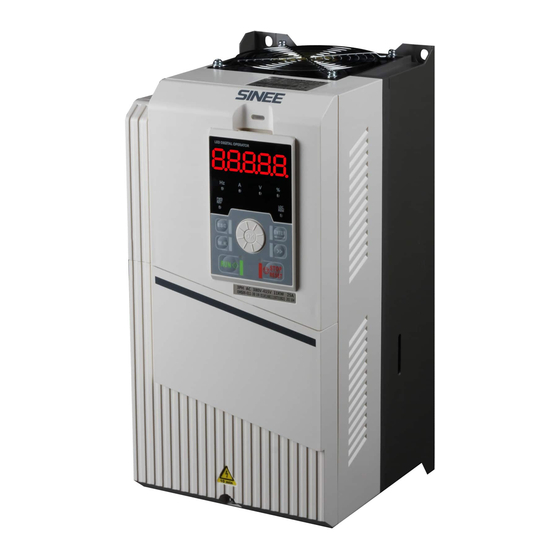
- Page 22 EM500 Open-Loop Vector Control Inverter User Manual 1.3 Description of Parts of EM500 Inverter Figure 1-7 Description of Parts of EM500 Inverter (4 kW) Figure 1-8 Description of Parts of EM500 Inverter (30 kW)
- Page 23 EM500 Open-Loop Vector Control Inverter User Manual Figure 1-9 Description of Parts of EM500 Inverter (450kW)
- Page 24 Check the overall appearance to see if they are damaged in transportation. Any loosened screws or other Check with a screwdriver if necessary. fastening parts. If you find any quality problem, please contact SINEE Direct Sale Department or the distributor. Nameplate ...
- Page 25 2.2 Overall and Installation Dimensions EM500 inverters can be categorized into 30 specifications for 4 overall dimensions and 12 installation dimensions (as shown in Figure 2–1 and Table 2–2). Keypad can be installed onto an iron panel separately with a hole size of 114.5±0.1(L)*71±0.1 (W) mm and the iron panel thickness of 1.2 - 2.0mm.
- Page 26 EM500 Open-Loop Vector Control Inverter User Manual (b) Overall Dimensions of 0.75 kW – 18 kW Inverters (c) Overall Dimensions of 22 kW – 75 kW Inverters...
- Page 27 EM500 Open-Loop Vector Control Inverter User Manual (d) Overall Dimensions of 90 kW – 400 kW Inverters (e) Overall Dimensions of 450 kW – 560 kW Inverters Figure 2-1 Overall Dimensions of EM500 Inverter and Keypad...
- Page 28 EM500 Open-Loop Vector Control Inverter User Manual Table 2-2 Overall and Installation Dimensions of EM500 Inverter Model No. W1/W2 Frame EM500-0R7G/1R5P-1B/ 2B/3B EM500-1R5G/2R2P-1B/ 2B/3B 153 108 75 EM500-2R2G/3R0P-1B/ 2B/3B EM500-4R0G/5R5P-3B EM500-5R5G/7R5P-3B 172 128 94 EM500-7R5G/9R0P-3B EM500-011G/015P-3B EM500-015G/018P-3B 210 165 136 7...
-
Page 29: Installation Site
EM500 Open-Loop Vector Control Inverter User Manual 2.3 Considerations for Installation Site Caution When carrying and transporting inverter, please hold its bottom. 3、 Only taking the face panel would result in the risk of hitting your foot due to its dropping. -
Page 30: Installation Direction And Space
(wall) for better cooling effect (see Figure 2–2). EM500 inverter (450 kW or above) must be installed with a cooling fan for forced air cooling. Its special air channel design enable cabinet to be installed at both left and right sides in parallel and only certain maintenance and operation space is required before and after cabinet. - Page 31 EM500 Open-Loop Vector Control Inverter User Manual 2.5 Assembly and Disassembly of Keypad Generally it’s not necessary to disassemble keypad while using an inverter. If necessary, observe the following methods to disassemble or install keypad. The keypad cover should be used for inverter 22kW and above if the keypad is disassembled Disassemble keypad: Put your fingers in finger slots on the top of keypad, press ...
- Page 32 Figure 2-4 Keypad Installation 2.6 Flush Mounting EM500 inverter (5.5 kW – 200 kW) can be changed to flush mounting type. Installation of EM500 inverter (22 kW or above): Remove top and bottom mounting holes of original housing (Figure 2–5) to the position shown in Figure 2–6, and install the...
- Page 33 Figure 2-5 Disassemble Top and Bottom Mounting Holes Figure 2-6 Assemble Top and Bottom Mounting Holes Installation of EM500 inverter (below 22kW): As shown in 2-7, insert left and right accessories for flush mounting into the slots at the left and right sides of the plastic shell, and tighten the two front and back screws.
- Page 34 EM500 Open-Loop Vector Control Inverter User Manual Figure 2-7 Left and Right Accessories for Flush Mounting...
- Page 35 EM500 Open-Loop Vector Control Inverter User Manual Figure 2-8 Installation Dimensions for Flush Mounting Table 2-3 Installation Dimensions for Flush Mounting W W1 D D1 D2 D3 Model No. Frame EM500-5R5G/7R5P-3B 188 166 300 258 172 128 172 EM500-7R5G/9R0P-3B EM500-011G/015P-3B...
- Page 36 EM500 Open-Loop Vector Control Inverter User Manual 3. Wiring 3.1 Connection to Peripherals Standard connection between EM500 and peripherals is shown in Figure 3–1. Figure 3-1 Connection of EM500 Inverter and Peripherals...
-
Page 37: Wiring Main Circuit Terminals
EM500 Open-Loop Vector Control Inverter User Manual 3.2 Wiring Main Circuit Terminals 3.2.1Main Circuit Terminal Block The main circuit terminals of EM500 comprise the following parts: 3-phase AC input terminals: R, S and T Grounding terminal: DC bus terminal: ... - Page 38 EM500 Open-Loop Vector Control Inverter User Manual d) Main Circuit Terminal Block of Models 45 - 75 kW e) Main Circuit Terminal Block of Models 90 - 200 kW f) Main Circuit Terminal Block of Models 220 - 400 kW g) Main Circuit Terminal Block of Models 450 - 560 kW Figure 3–2 Main Circuit Terminal Block...
- Page 39 220 - 400 kW or above: There are 2 wiring terminal blocks for each phase. 3.2.2Main Circuit Terminal Functions The main circuit terminal functions of EM500 are shown in Table 3–2 and please correctly wire terminals according to functions. Table 3–2 Main Circuit Terminal Functions Terminal No.
- Page 40 EM500-022G/030P-3~EM500-200G/220P-3 EM500-220G/250P-3~ EM500-560G/630P-3 Figure 3-3 Internal Main Circuit of Inverter 3.2.4Standard Wiring of Main Circuit The standard wiring of the main circuit of EM500 inverter is shown in Figure 3–4. EM500-0R7-3B - EM500-018-3B EM500-022-3 - EM500-560-3 Figure 3-4 Standard Wiring of Main Circuit...
- Page 41 EM500 Open-Loop Vector Control Inverter User Manual 3.2.5Wiring on Input Side of Main Circuit 3.2.5.1Circuit Breaker Installation An air circuit breaker (MCCB) corresponding to inverter is required between power supply and input terminals. The capacity of MCCB shall be 1.5 to 2 times that of the rated current of ...
- Page 42 EM500 Open-Loop Vector Control Inverter User Manual shall not be longer than once every 30 minutes. Inverter will not automatically start after power failure. 3.2.5.4Connection to Terminal Block Input power can be connected to R, S and T randomly irrespective of their phase sequence on the terminal block.
- Page 43 EM500 Open-Loop Vector Control Inverter User Manual MCCB EM600 普通噪声 EM500 General Noise Inverter Filter 变频器 滤波器 Other 其它控 Control 制设备 Device MCCB EM600 EM500 Inverter 变频器 Other 其它控 普通噪声 General Control Noise Filter 滤波器 制设备 Device Figure 3-7 Incorrect Installation of Noise Filter 3.2.6Wiring on Output Side of Main Circuit...
- Page 44 EM500 Open-Loop Vector Control Inverter User Manual 3.2.6.2Never Connect Power Supply Cable to Output Terminals Never connect power supply cable to output terminals. If output terminals are connected to power supply, the internal parts of inverter would be damaged. 3.2.6.3Never Short-Circuit or Ground Output Terminals Never touch output terminals with bare hands or connect output cable to inverter housing, so as to avoid electric shock or short circuit.
- Page 45 EM500 Open-Loop Vector Control Inverter User Manual Figure 3-8 Noise Filter Installation on the Output Side 3.2.6.7Countermeasures Against Inductive Interference In addition to the installation of a noise filter, the method of wiring all output cable into grounded metal pipe can be adopted to suppress the inductive interference on the output side.
- Page 46 EM500 Open-Loop Vector Control Inverter User Manual 3.2.6.9Wiring Distance Between Inverter and Motor The longer the wiring distance between inverter and motor is, the higher the carrier frequency will be and the greater the high-frequency harmonic leakage current on its cable will be accordingly.
- Page 47 EM500 Open-Loop Vector Control Inverter User Manual EM500-075G/905P-3/3B EM500-090G/110P-3 EM500-110G/132P-3 EM500-132G/160P-3 EM500-160G/185P-3 EM500-185G/200P-3 31.0 –39.0 EM500-200G/220P-3 EM500-220G/250P-3 2*120 EM500-250G/280P-3 2*M10 17.0 – 22.0 EM500-280G/315P-3 EM500-315G/355P-3 2*150 EM500-355G/400P-3 2*M12 31.0 – 39.0 EM500-400G/450P-3 2*180 EM500-450G/500P-3 EM500-500G/560P-3 2*M16 45.0 – 55.0 2*270 EM500-560G/630P-3 Note: 1.
- Page 48 EM500 Open-Loop Vector Control Inverter User Manual Please select the grounding wire of the specifications as stipulated in the Technical Standards of Electrical Equipment and keep it as short as possible when connecting to the ground point. Do not allow the grounding cable to form a circuit when two or more ...
- Page 49 EM500 Open-Loop Vector Control Inverter User Manual See Figure 3–12 for control circuit terminal block. Figure 3-12 Control Circuit Terminal Block Note: 1. Jump wires J9 and J10 of the terminal block are equipped by the manufacturer. No user is allowed to change them, or else inverter may not work normally.
- Page 50 EM500 Open-Loop Vector Control Inverter User Manual Terminal 1 Input impedance: 1MΩ Input range: DC 0 - 10 V/0 - 20 mA; select the voltage/current mode by switch S4 on the Analog Input terminal block AI2-GND Terminal 2 Input impedance: Voltage mode 1 MΩ, current mode 250 Ω...
- Page 51 EM500 Open-Loop Vector Control Inverter User Manual Analog Output M1-GND Output range: DC 0 - 10 V. S2 is VOID. Terminal 1 Analog Output Analog Output Output range: DC 0 - 10 V/0 - 20 mA; M2-GND Terminal 2 selected by switch S3 on the terminal block.
- Page 52 3.3.4 Wiring of Terminals AI2 and AI3 (as shown in Figure 3-15) Figure 3-16 Wiring of Terminals AI2 and AI3 3.3.5Wiring of Multi-function Input Terminal Multi-function input terminals of EM500 inverter adopt full bridge rectifier. PLC terminal is a common terminal for X1-X7. The current passing through PLC terminal can...
- Page 53 EM500 Open-Loop Vector Control Inverter User Manual be either forward (NPN Mode) or reverse (PNP Mode), so that it is flexible to connect terminals X1 - X7 to external devices. Typical wiring methods are shown in the following: A. NPN mode with internal power supply B.
- Page 54 EM500 Open-Loop Vector Control Inverter User Manual leakage current should be less than the holding current of the contactor or relay under control), VDR and fly-wheel diode (for DC electromagnetic circuit, please pay attention to the polarity at installation). Components of absorption circuit should be installed near two sides of relay or contactor coil.
- Page 55 Realize networking control of host controller (PLC or PLC controller) and inverter by connecting to host controller for communication. RS485, RS485/RS232 converter and EM500 inverter are wired as shown in Figures 3-18, 3-19 and 3-20. RS485 terminal of single inverter directly connects to host controller for ...
- Page 56 PC (PC or PLC controller) and the inverter network control. More than one inverter is connected, multi-machine communication can be achieved between. PC and EM500 series inverter connected as shown in Figure 3 22, Figure 3 23 shows. Single inverter CANSinee bus directly connected with the host computer...
- Page 57 It’s recommended to use 0.5 - 1 mm cable as the control circuit cable. Terminal block of EM500 inverter shall be through control circuit connection terminal. Please use a cross screwdriver PH0 for installation with tightening torque of 0.5 N.m.
- Page 58 contacting other signal cable and housing of device. It’s not allowed to contact various ports or components without ESD measures. 3.3.12Standard Wiring of Control Circuit Standard wiring of control circuit of EM500 inverter is shown in Figure 3–22.
- Page 59 EM500 Open-Loop Vector Control Inverter User Manual Braking Resistor 制动电阻 MCCB R/L1 3-Phase 三相 S/L2 Power 电源 接 Supply EM600 Grounding T/L3 接 地 Grounding 地 24V输出 24V Output Keypad Interface 键盘接口 200mA 多 功 Function Extension Card 功能扩展卡接口 能...
- Page 60 EM500 Open-Loop Vector Control Inverter User Manual 3.4 Extending Keypad Wire 1) External keypad interface adopts RJ45 interface and the extending wire is common network cable (connection plug executes standard EIA/TIA568B). 2) See Figure 3-22 for wiring of keypad extension line.
- Page 61 4. Keypad Operation 4.1 Keypad Function 4.1.1Structure of LED Keypad Control panels of EM500 can be classified into two categories: LED keypad and LCD keypad. LED keypad comprises a 5-bit LED display, 6 operation buttons, 1 digital potentiometer and 8 status and unit indicators.
- Page 62 EM500 Open-Loop Vector Control Inverter User Manual Table 4-1 Functions of Buttons and Indicators of LED Keypad Button/Indicator Name Function Select the group number and the function code Right Shift Switch monitoring parameters Back to previous menu. Escape Escape from editing present parameter by entering menu mode from monitoring mode.
- Page 63 EM500 Open-Loop Vector Control Inverter User Manual Frequency On when present parameter is frequency. Indicator Current Indicator On when present parameter is current. Voltage Indicator On when present parameter is voltage. On when present parameter is percentage. Percentage Indicator Forward/Reverse On at frequency is negative.
- Page 64 EM500 Open-Loop Vector Control Inverter User Manual When keypad is powered, default display is the first monitoring parameter of level 0; press to enter menu level 1, from which using digital potentiometer to select a menu mode. The operation procedure for menu mode selection is shown in Figure 4–2.
- Page 65 EM500 Open-Loop Vector Control Inverter User Manual Figure 4-3 Operation Procedure from Power-on to Setting F03.28=5.28 Under all menu modes, press to save parameter change after having changed the parameter. The difference is that after having saved the parameter: it enters the next function code under all menu modes;...
- Page 66 EM500 Open-Loop Vector Control Inverter User Manual Press to cancel parameter change under the third level menu; if the function code is changed to a value as it was, it will exit the third level menu and get back to the second level menu;...
- Page 67 EM500 Open-Loop Vector Control Inverter User Manual Figure 4-5 Example of User-Defined Mode Setting Press under the user-defined mode to enter the second level menu, which only displays 32 user-defined codes of F11. Select codes among these 32 function codes according to user needs;...
- Page 68 EM500 Open-Loop Vector Control Inverter User Manual Figure 4-6 Changing Function Code under User-Defined Mode Rotate digital potentiometer in the second level menu under the user-defined mode to switch to the parameters set by previous or next user, because user can not add or remove any function parameter of the second level menu.
- Page 69 EM500 Open-Loop Vector Control Inverter User Manual previous/next non-factory default of the function code will be displayed accordingly. The lowest position of cursor will flash if current function code is permitted for change. The method of changing parameters is the same as that in the third level menu under all menu mode;...
-
Page 70: Parameter Copy
EM500 Open-Loop Vector Control Inverter User Manual 4.4 Operation Monitoring There are two kinds of monitoring: If set F12.32 as 0 it’s monitoring mode 0. When the menu displayed is the level 0 monitoring menu, press to switch the sequence of 8 monitoring parameters of each function code as per F12.04 - F12.08. - Page 71 EM500 Open-Loop Vector Control Inverter User Manual 2. If inverters adopt different CPUA software versions, keypad prompts “go on” at the time of downloading parameters. Now, user needs to know whether the parameters are available for downloading at these two different versions. If available, user may press to cancel current operation.
- Page 72 EM500 Open-Loop Vector Control Inverter User Manual 5. Trial Operation 5.1 Trial Operation Procedure Follow the steps in table 5–1 for trial operation of EM500 inverter. Table 5-1 Steps of Trial Operation Step Description Check the power of inverter and install inverter as per Installation requirements in Chapter 2.
- Page 73 EM500 Open-Loop Vector Control Inverter User Manual Inverter frequency and fault output. For hoisting equipment, the following protection settings shall be invalid: Current limit protection and overvoltage stall protection. Before running for the first time, please conduct motor parameter autotuning, in order to obtain the correct electrical parameters of the controlled motor.
- Page 74 Input DC current to motor before start or stop, in order to generate DC Braking braking torque and thus rapidly stop the rotating motor. Sett Special With multiple multi-function input and output ports, EM500 can Terminal offer various kinds of application solution when in use with Control external controller.
- Page 75 EM500 Open-Loop Vector Control Inverter User Manual Input power cable is connected to inverter’s input terminals R, S and T. Inverter’s output terminals U, V and W are connected to motor’s input terminals. Control circuit terminals are correctly connected to the control devices and ...
- Page 76 F27 Winding Applications Parameter Group F28 Air compressor Applications Parameter Group ★ Note: If some parameters of EM500 are not used, 0 is returned after read; if user retains some options of some parameters, these options can be set, but may result in abnormal running of inverter.
- Page 77 EM500 Open-Loop Vector Control Inverter User Manual The value of the whole function code represents present Overall parameter selection or meaning. Decimal Represents some options or present meaning of present Digit function code. Each binary digit represents some options or present...
- Page 78 EM500 Open-Loop Vector Control Inverter User Manual 6.2 Function Parameter Table Function Range Unit Default Type Basic Function Parameter Group F00.00 Not Used Drive Control Mode 0: V/F control (VVF) F00.01 〇 of Motor 1 1: Sensorless Vector Control (SVC)
- Page 79 EM500 Open-Loop Vector Control Inverter User Manual Direct Setting 8: digital Potentiometer 9: Not Used 10: Process PID 11: Simple PLC 0: Main Frequency Source A 1: Auxiliary Frequency Source B 2: Main and Auxiliary Arithmetic Results 3: Switching between Main Frequency...
- Page 80 EM500 Open-Loop Vector Control Inverter User Manual Synthetic Gain of F00.12 Main and Auxiliary 0.0 - 300.0 100.0 ● Frequency 0: Synthetic Frequency of Main and Auxiliary Channels 1: AI1 * Synthetic Frequency of Main and Auxiliary Channels 2: AI2 * Synthetic Frequency of Main...
- Page 81 EM500 Open-Loop Vector Control Inverter User Manual 0: Permit Forward/Reverse F00.21 Reverse Control 〇 1: Prohibit Reverse F00.22 F/R Deadband Time 0.00 - 650.00 0.00 ● 1.0 - 16.0 (inverter rated power 0,75 – 4.00kW) 1.0 - 10.0 (inverter rated power 5.50 - 7.50 kW)
- Page 82 EM500 Open-Loop Vector Control Inverter User Manual 0.01 - 600.00 (Motor Rated Power ≤ 75 Up To F01.03 Motor Rated Current Specific 〇 0.1 - 6000.0 (Motor Rated Power >75 Model Up To Motor Rated F01.04 0.01 - 600.00 Specific 〇...
- Page 83 EM500 Open-Loop Vector Control Inverter User Manual Induction Motor F01.15 Field Weakening 10.00 - 100.00 80.00 〇 Factor 2 Induction Motor F01.16 Field Weakening 10.00 - 100.00 75.00 〇 Factor 3 Induction Motor F01.17 Field Weakening 10.00 - 100.00 72.00 〇...
- Page 84 EM500 Open-Loop Vector Control Inverter User Manual 0: No Autotuning 1: Stationary Autotuning of Induction Motor 2: Rotational Autotuning of Induction Motor Parameter F01.34 Motor 〇 Autotuning 11: Stationary Autotuning of Synchronous Motor 12: Rotational Autotuning of Synchronous Motor Input Terminal Function Group...
- Page 85 EM500 Open-Loop Vector Control Inverter User Manual Card) 25: Switch Run Command to Communication X10 Numeric Input 26: Frequency Source Switching F02.13 Function (Expansion 〇 27: Clear Timed Running time Card) 28: Switch between Speed Control and X11 Numeric Input Torque Control F02.14...
- Page 86 EM500 Open-Loop Vector Control Inverter User Manual 54: Switch Main Frequency Source to 55: Switch Main Frequency Source to High-Frequency Pulse Input 56: Switch Main Frequency Source to Communication Setting 57: Inverter Enabled 58-78: Not Used 79: Remote Start 80: Power Frequency Conversion...
- Page 87 EM500 Open-Loop Vector Control Inverter User Manual Input Terminal 0: Positive Logic, Enabled at On/Disabled at Off 1: Negative Logic, Disabled at On/Enabled at Off Filter Times of 0-100, 0 for No Filter, n for sampling F02.17 Numeric Input 〇...
- Page 88 EM500 Open-Loop Vector Control Inverter User Manual Ones Place: AI1 0: Analog Input 1: Numeric Input (0 for less than 1V, 1 for over 3V, contrary to the last time for 1V-3V) Tens Place: AI2 0: Analog Input Analog Input F02.31...
- Page 89 EM500 Open-Loop Vector Control Inverter User Manual Maximum Input of F02.35 F02.33 - 10.00 9.90 ● Curve 1 Setting Corresponding to F02.36 –100.0 - +100.0 100.0 ● Maximum Input of Curve 1 Minimum Input of F02.37 -10.00 - F02.39 0.10 ●...
- Page 90 EM500 Open-Loop Vector Control Inverter User Manual Maximum Input of Curve 3 Minimum Input of F02.49 -10.00 - F02.51 -9.90 ● Curve 4 Setting Corresponding to F02.50 –100.0 - +100.0 -100.0 ● Minimum Input of Curve 4 Input of Inflexion 1 F02.51...
- Page 91 EM500 Open-Loop Vector Control Inverter User Manual Y3 Output Function FDT2 F03.04 ○ (expansion card) 5: Reverse running (REV) 6: Jogging 7: Inverter Fault 8: Inverter Ready 9: Upper Limit Frequency Reach 10: Lower Limit Frequency Reach 11: Current Limit Enabled...
- Page 92 EM500 Open-Loop Vector Control Inverter User Manual 64: I pump control 65~66: Not Used 67: Brake Control 68: Material supply disruptions Detection Output 69: FDT1 Lower Bound (Pulse) 70: FDT2 Lower Bound (Pulse) 71: FDT1 Lower Bound (Pulse JOG Is...
- Page 93 EM500 Open-Loop Vector Control Inverter User Manual Time R2 Ineffective Delay F03.16 0.000 - 30.000 0.000 ● Time Y1 Monopulse F03.17 0.001 - 30.000 0.250 ● Output Time Y2 Monopulse F03.18 0.001 - 30.000 0.250 ● Output Time R1 Monopulse F03.19...
- Page 94 EM500 Open-Loop Vector Control Inverter User Manual Pulse Output Filter Time of Y2 F03.26 High-Frequency 0.00 - 10.00 0.10 ● Pulse Output F03.27 M1 Output Offset -100.0 - 100.0 ● F03.28 M1 Output Gain -10.00 - 10.00 1.00 ● F03.29 M2 Output Offset -100.0 - 100.0...
- Page 95 EM500 Open-Loop Vector Control Inverter User Manual 0.00 - System acceleration time/2 (F15.13=0) S Curve Start 0.0 - System acceleration time/2 F04.15 Section Time at 1.00 ● (F15.13=1) Acceleration 0 - System acceleration time/2 (F15.13=2) 0.00 - System acceleration time/2 (F15.13=0)
- Page 96 EM500 Open-Loop Vector Control Inverter User Manual Terminal Start 0: Not to Confirm F04.27 Command 〇 1: Confirm Reconfirmation F04.28 Not Used Zero speed F04.29 0.00 – 5.00 0.25 ● frequency Initial Position 0: Disabled F04.30 Search after ● 1: Enabled...
- Page 97 EM500 Open-Loop Vector Control Inverter User Manual 6: Communication Percentage Setting Note: Motor Rated Voltage is 100% Numeric Setting of 0.0 - 100.0 (100.0= Motor Rated F05.08 VF Separation ● Voltage) Voltage Rise Time of VF F05.09 0.00 - 60.00 2.00...
- Page 98 EM500 Open-Loop Vector Control Inverter User Manual Frequency 1 Switching Switching Frequency 1 - Maximum F06.05 10.00 ● Frequency 2 Frequency F00.16 Speed Loop F06.06 Anti-Saturation 0.000 - 1.000 0.500 ● Factor Time Constant of F06.07 Output Filter of 0.000 - 0.100 0.001...
- Page 99 EM500 Open-Loop Vector Control Inverter User Manual 2: No output SVC Zero Frequency F06.18 50.0 - 400.0 (100.0=Idling Current) 100.0 〇 Band-Type Brake Current F06.19 Not Used Voltage F06.20 0 - 100 ● Feedforward Gain Field Weakening 0: Disabled F06.21...
- Page 100 EM500 Open-Loop Vector Control Inverter User Manual Gain of Injection Current Integral Time of Low Frequency F06.31 0.00 - 300.00 10.00 ● Range Regulator of Injection Current Frequency of Injection Current at 0.00 - 100.00 (100.00= Motor Rated F06.32 20.00 ●...
- Page 101 EM500 Open-Loop Vector Control Inverter User Manual F06.45 Synchronous Motor F06.46 speed tracking 0.00~10.00 1.00 〇 proportional gain Synchronous Motor F06.47 speed tracking 0.00~10.00 1.00 〇 integral gain Synchronous Motor F06.48 speed tracking filter 0.00~10.00 0.40 〇 time Synchronous Motor F06.49...
- Page 102 EM500 Open-Loop Vector Control Inverter User Manual Overvoltage Stall 131.0 F07.07 110.0 - 150.0 (380V,100.0=537V) 〇 Control Voltage (703V) 60.0 - Judgment Voltage at Power Undervoltage Stall F07.08 Failure Ending (100.0= Standard Bus 76.0 〇 Control Voltage Voltage) Judgment Voltage at Undervoltage Stall Control Voltage - F07.09...
- Page 103 EM500 Open-Loop Vector Control Inverter User Manual Load Detection F07.23 0.0 - 60.0 ● Time 0: Coast to Stop F07.24 Offload Protection 〇 1: Stop as per Set Stop Mode F07.25 Not Used F07.26 0: Disable F07.27 AVR 1: Enable 〇...
- Page 104 EM500 Open-Loop Vector Control Inverter User Manual Tens Place: Power Failure Memory 0: Disabled (Start from Preset Speed 1) 1: Enabled (Start at Power Failure) Simple PLC Time 0: s F08.18 ● Unit 1: min Ones Place: Running Direction 0: Forward...
- Page 105 EM500 Open-Loop Vector Control Inverter User Manual 1: Reverse Tens Place: Acceleration/Deceleration Time 0: Acceleration/Deceleration Time 1 1: Acceleration/Deceleration Time 2 2: Acceleration/Deceleration Time 3 3: Acceleration/Deceleration Time 4 Running Time of F08.26 0.0 - 6000.0 ● Preset Speed 4...
- Page 106 EM500 Open-Loop Vector Control Inverter User Manual Running Time of F08.32 0.0 - 6000.0 ● Preset Speed 7 Ones Place: Running Direction 0: Forward 1: Reverse Tens Place: Acceleration/Deceleration Setting of Preset F08.33 Time ● Speed 8 0: Acceleration/Deceleration Time 1...
- Page 107 EM500 Open-Loop Vector Control Inverter User Manual 0: Acceleration/Deceleration Time 1 1: Acceleration/Deceleration Time 2 2: Acceleration/Deceleration Time 3 3: Acceleration/Deceleration Time 4 Running Time of F08.40 0.0 - 6000.0 ● Preset Speed 11 Ones Place: Running Direction 0: Forward...
- Page 108 EM500 Open-Loop Vector Control Inverter User Manual Speed 15 0: Forward 1: Reverse Tens Place: Acceleration/Deceleration Time 0: Acceleration/Deceleration Time 1 1: Acceleration/Deceleration Time 2 2: Acceleration/Deceleration Time 3 3: Acceleration/Deceleration Time 4 Running Time of F08.48 0.0 - 6000.0 ●...
- Page 109 EM500 Open-Loop Vector Control Inverter User Manual 2: Automatic Switching by Offset PID Parameter F09.12 0.00 - F09.13 20.00 ● Switching Offset 1 PID Parameter F09.13 F09.12 - 100.00 80.00 ● Switching Offset 2 F09.14 PID Initial Value 0.00 - 100.00 0.00...
- Page 110 EM500 Open-Loop Vector Control Inverter User Manual PID Setting Feedback Range) F09.29 Sleep Delay Time 0.0 - 6500.0 ● Awakening Action 0.00 - 100.00 (100.00 corresponds to F09.30 0.00 ● Point PID Setting Feedback Range) Awakening Delay F09.31 0.0 - 6500.0 ●...
- Page 111 EM500 Open-Loop Vector Control Inverter User Manual stop bits) 4: 1-8-E-2 (1 start bit + 8 data bits + 1 even parity +2 stop bits) 5: 1-8-O-2 (1 start bit + 8 data bits + 1 odd parity +2 stop bits) 0.0 - 60.0, 0.0: Disabled (also works for...
- Page 112 EM500 Open-Loop Vector Control Inverter User Manual DeviceNet Expansion Card Response Delay Time of Process F10.14 Data of 0.0 - 200.0 〇 Communication Card Ones Place: CANopen 0: 125K 1: 250K Bit Rate of 2: 500K Communication F10.15 3: 1M 〇...
- Page 113 EM500 Open-Loop Vector Control Inverter User Manual PZD11 Received Data Type 65535 F10.27 〇 PZD12 Received Data Type 65535 F10.28 〇 PZD13 Received Data Type 65535 F10.29 〇 PZD14 Received Data Type 65535 F10.30 〇 PZD15 Received Data Type 65535 F10.31...
- Page 114 EM500 Open-Loop Vector Control Inverter User Manual Sent Data Type 65535 F10.46 〇 PZD16 Ones Place: Profibus-DP 0: Initialization Status 1: Wait for Parameterization Status 2: Wait for Configuration Status 3: Data Exchange Status 4: Modbus Communication Abnormality Status 5: Factory Test Status...
- Page 115 EM500 Open-Loop Vector Control Inverter User Manual Communication 0:disable F10.52 card manual reset ● 1:enable selection CANSinee F10.53 Communication 1~31 〇 address 0:125K CANSinee 1:250K F10.54 Communication 〇 2:500K baud rate 3:1M CANSinee 0.0 - 60.0, 0.0: Disabled (also works for F10.55...
- Page 116 EM500 Open-Loop Vector Control Inverter User Manual User-Defined F11.12 U02.00 ● Parameter 13 User-Defined F11.13 U02.01 ● Parameter 14 User-Defined F11.14 U02.02 ● Parameter 15 User-Defined F11.15 U03.00 ● Parameter 16 User-Defined F11.16 U03.02 ● Parameter 17 User-Defined F11.17 U03.21 ●...
- Page 117 EM500 Open-Loop Vector Control Inverter User Manual Keypad and Display Function Group 0: No Function 1: Forward JOG 2: Reverse JOG F12.00 M.K 3: Forward/Reverse Switch 〇 4: Rapid Stop 5: Coast to Stop 6: Cursor Left Shift 0: Valid Only at Keypad Control F12.01 STOP...
- Page 118 EM500 Open-Loop Vector Control Inverter User Manual bit2: AI4 bit3: PID Input bit4: PID Feedback bit5: Count Value bit6: Actual Length bit7: High-Frequency Pulse Input Frequency: kHz 00000000 - 11111111 (o for non-displaying, 1 for displaying) bit0: High-Frequency Pulse Input...
- Page 119 EM500 Open-Loop Vector Control Inverter User Manual 1: Reset (exclusive of motor parameter, inverter parameter, manufacturer parameter, running and power-on time record) Accumulated F12.15 0 - 65535 × Power-On Time h Accumulated F12.16 0 - 59 min XXX × Power-On Time min Accumulated F12.17...
- Page 120 EM500 Open-Loop Vector Control Inverter User Manual Number 3 0: Chinese F12.31 LCD Language 1: English ● 2: Not Used 0:Mode 0 F12.32 Monitor mode ● 1:Mode 1 F12.33 Mode 1 display parameter 1(LED 0.00~99.99 18.00 ● Stop status display parameter 5)...
- Page 121 EM500 Open-Loop Vector Control Inverter User Manual Torque Control Parameter Group Speed/Torque 0: Speed Control F13.00 〇 Control 1: Torque Control 0: Numeric Torque Setting F13.02 1: AI1 2: AI2 3: AI3 4: AI4 (Expansion Card) 5: High-Frequency Pulse Input (X7) F13.01 Torque Setting...
- Page 122 EM500 Open-Loop Vector Control Inverter User Manual Compensation Kinetic Friction F13.13 Torque 0.0 - 100.0 ● Compensation F13.14 ~F13.1 Not Used ● F13.18 Reverse speed limit 0~100 % 100 ● F13.19 Reverse torque limit 0~1 ● Motor 2 Parameter Group...
- Page 123 EM500 Open-Loop Vector Control Inverter User Manual Induction Motor 0.1 - 6000.0 (Motor Rated Power ≥ Specific 75kW) Model 1 - 60000 (Motor Rated Power ≤ 75kW) Up To Rotor Resistor of F14.10 0.1 - 6000.0 (Motor Rated Power ≥...
- Page 124 EM500 Open-Loop Vector Control Inverter User Manual of Synchronous 75kW) Specific Motor 0.001 - 60.000 (Motor Rated Power≥ Model 75kW) Counter Up To Electromotive Force 10.0 - 2000.0 (Counter Electromotive F14.22 Specific 〇 of Synchronous Force of Rated Rotation Speed)
- Page 125 EM500 Open-Loop Vector Control Inverter User Manual Output Filter of Speed Loop Speed Control Slip F14.44 50.00 - 200.00 100.00 ● Gain 0: F06.10 and F06.11 1: AI1 2: AI2 Speed control 3: AI3 F14.45 torque limit source 〇...
- Page 126 EM500 Open-Loop Vector Control Inverter User Manual Excitation Current Voltage F14.56 0 - 100 ● Feedforward Gain Field Weakening 0: Disabled F14.57 Control Options of 1: Direct Calculation 〇 Synchronous Motor 2: Automatic Adjustment Field Weakening F14.58 Factor of 100.00 - 200.00 100.00...
- Page 127 EM500 Open-Loop Vector Control Inverter User Manual Injection Current Frequency of Injection Current at 0.00 - 100.00 (100.00= Motor Rated F14.68 20.00 ● High Frequency Frequency) Range Injection Current at 0.0 - 30.0 (100.0= Motor Rated F14.69 High Frequency ●...
- Page 128 EM500 Open-Loop Vector Control Inverter User Manual F14.80 Motor 2 V/F Curve 0: Straight Line V/F ● Setting 1: Multi-Dot Polyline V/F F14.81 Motor 2 Multipoint ● VF Frequency Point 0.00~F14.83 0.50 F14.82 Motor 2 Multipoint ● 0.0~100.0(100.0 = rated voltage)...
- Page 129 EM500 Open-Loop Vector Control Inverter User Manual 0.00 - 650.00 (F15.13=0) F15.07 Acceleration Time 4 0.0 - 6500.0 (F15.13=1) 15.00 ● 0 - 65000 (F15.13=2) 0.00 - 650.00 (F15.13=0) F15.08 Deceleration Time 4 0.0 - 6500.0 (F15.13=1) 15.00 ● 0 - 65000 (F15.13=2)
- Page 130 EM500 Open-Loop Vector Control Inverter User Manual Bandwidth Output Frequency F15.21 Detection Range 0.00 - Maximum Frequency F00.16 30.00 〇 FDT1 F15.22 FDT1 Hysteresis -(Fmax-F15.21)~F15.21 2.00 〇 Output Frequency F15.23 Detection Range 0.00 - Maximum Frequency F00.16 20.00 〇 FDT2 F15.24 FDT2 Hysteresis...
- Page 131 EM500 Open-Loop Vector Control Inverter User Manual Options PWM Modulation F15.37 0.00 - Maximum Frequency F00.16 15.00 ● Method 0: Disabled Deadband F15.38 1: Compensation Mode 1 〇 Compensation Mode 2: Compensation Mode 2 Terminal Jog 0: Disabled F15.39 〇...
- Page 132 EM500 Open-Loop Vector Control Inverter User Manual 0: General models 1: Application of Water supply F16.00 Industry Application 〇 2: Application of Air compressor 3: Application of Winding rolling 1~65535(F16.13=0) 0.1~6553.5(F16.13=1) F16.01 Set Length 1000 ● 0.01~655.35(F16.13=2) 0.001~65.535(F16.13=3) Pulse Count Per F16.02...
- Page 133 EM500 Open-Loop Vector Control Inverter User Manual Virtual I/O Function Group VX1 Virtual Input F17.00 〇 Function VX2 Virtual Input F17.01 〇 Function VX3 Virtual Input F17.02 〇 Function VX4 Virtual Input F17.03 〇 Function Same as numeric input terminal...
- Page 134 EM500 Open-Loop Vector Control Inverter User Manual Delay Time VX3 Ineffective F17.16 0.000 - 30.000 0.000 ● Delay Time VX4 Effective F17.17 0.000 - 30.000 0.000 ● Delay Time VX4 Ineffective F17.18 0.000 - 30.000 0.000 ● Delay Time VY1 Virtual Output F17.19...
- Page 135 EM500 Open-Loop Vector Control Inverter User Manual Delay Time VY2 Effective F17.31 0.000 - 30.000 0.000 ● Delay Time VY2 Ineffective F17.32 0.000 - 30.000 0.000 ● Delay Time VY3 Effective F17.33 0.000 - 30.000 0.000 ● Delay Time VY3 Ineffective F17.34...
- Page 136 EM500 Open-Loop Vector Control Inverter User Manual Simple PLC F18.11 1 - 15 × Running Stage PLC Running Time F18.12 0.0 - 6000.0 × of Present Stage F18.13 Not Used F18.14 Load Speed 0 - 65535 rpm xxx × UP/DOWN Offset F18.15...
- Page 137 EM500 Open-Loop Vector Control Inverter User Manual Frequency: kHz High-Frequency F18.32 Pulse Input 0 - 65535 × Frequency: Hz F18.33 Count Value 0 - 65535 × F18.34 Actual Length 0 - 65535 × Remaining Time of min xxx F18.35 0.0 - 6500.0 ×...
- Page 138 EM500 Open-Loop Vector Control Inverter User Manual Ol: Inverter Overload OH: Inverter Overheating Protection E11: Parameter Setting Conflict E12: Motor Overheating E13: Motor Overload E14: External Fault E15: Inverter EEPROM Fault E16: Communication Abnormality E17: Temperature Sensor Abnormality E18: Soft Start Relay Off...
- Page 139 EM500 Open-Loop Vector Control Inverter User Manual E40: Profibus-DP Configuration Data Error E41: Profibus-DP IO Disconnection E42: Not Used E43: Material supply disruptions Error E44: Winding traverse Error E45: Air pressure over voltage Error E46: Air pressure feedback Disconnection E47: Oil Temperature Over-temperature...
- Page 140 EM500 Open-Loop Vector Control Inverter User Manual 4: Reverse Deceleration 5: Forward Constant Speed 6: Reverse Constant Speed Working Time at F19.05 × Fault F19.06 Last Fault Type See F19.00 Parameter Description × Output Frequency at F19.07 0.00 × Fault Output Current at F19.08...
- Page 141 EM500 Open-Loop Vector Control Inverter User Manual Under-voltage alarm F25.05 pressure of pipe 0.1~F09.03 ● networks overpressure And under-voltage F25.06 0~3600 ● protection action time F25.07 Not Used F25.15 0: No H Pump 1: H Pump is Sewage pump F25.16 H Pump Definition 〇...
- Page 142 EM500 Open-Loop Vector Control Inverter User Manual channel selection 2: AI3 3: AI4 4: HDI 5: Communications input Upper Limit water F25.40 0.0~100.0 60.0 ● level analog level Lower Limit water F25.41 0.0~100 40.0 ● level analog level Water shortage level F25.42...
- Page 143 EM500 Open-Loop Vector Control Inverter User Manual F25.74 Reset the current 0: Not Used F25.75 〇 running time 1: Reset Application of water supply advanced group The Gregorian F26.00 2000~2099 〇 calendar year Set The Gregorian F26.01 01~12(Month). 01~31(Day) 〇...
- Page 144 EM500 Open-Loop Vector Control Inverter User Manual timing choice of 1: Effective on Sunday, Saturday is water supply invalid 2: Saturday and Sunday is invalid F26.18 T1 Start time 00.00~23.59 0.00 〇 F26.19 Pressure at time T1 F25.03~F25.02 〇 F26.20 T2 Start time T1~23.59...
- Page 145 EM500 Open-Loop Vector Control Inverter User Manual Control 0: Automatic reset 1: Terminal reset Tens Place:Feedforward power off and parking choice 0: Power off saved 1: Power off unsaved Upper Limit F27.04 0.00~500.00 500.00 〇 feedforward gain Feedforward initial F27.05 0.00~500.00...
- Page 146 EM500 Open-Loop Vector Control Inverter User Manual Tens Place:Material supply disruptions detection control 0: Detect when output is greater than the lower limit of material supply interrupt detection 1: No detection hundreds place: Material supply disruptions process mode 0:Only Error terminal act...
- Page 147 EM500 Open-Loop Vector Control Inverter User Manual detection minimum frequency Winding traverse F27.28 signal invalid judge 0.1~20.0 10.0 ● time Winding traverse F27.29 signal effective 0.1~20.0 ● judge time Material supply disruptions F27.30 1~100 ● Detection filtering time F27.31 Not Used F27.35...
- Page 148 EM500 Open-Loop Vector Control Inverter User Manual 2: AI3 3: AI4 4: HDI Pressure Digital F28.11 0.00~Upper Limit Pressure value MPa 0.80 ● given Early-warning Pressure Digital given~ Warning F28.12 MPa 0.98 ● pressure pressure Early-warning pressure~ Maximum F28.13 Warning pressure MPa 1.00...
- Page 149 EM500 Open-Loop Vector Control Inverter User Manual 2: KTY84-130/150 3: PTC130/150 hundreds place: Air pressure sensor 0: General channel 1: Interface card Maximum F28.26 60.0~160.0 125.0 ℃ 〇 temperature range 0: AI1 1: AI2 Temperature F28.27 2: AI3 〇 feedback selection...
- Page 150 EM500 Open-Loop Vector Control Inverter User Manual Temperature limit F28.40 0.00~100.00 0.00 ● deviation Temperature F28.41 disconnection 0.0~ Maximum temperature range ℃ 〇 detection threshold Temperature 0.0~6000.0, 0.0 :The Function is F28.42 disconnection ● Disabled detection Time 0: AI1 1: AI2 Motor Temperature F28.43...
- Page 151 EM500 Open-Loop Vector Control Inverter User Manual protection Third place: Pressure feedback disconnection protection Fourth place: Temperature overrun protection Fifth place: Temperature feedback disconnection protection Sixth place: Not Used Seventh place: The motor feedback disconnection protection Eighth place: Not Used...
- Page 152 EM500 Open-Loop Vector Control Inverter User Manual 3: Curve 4 0: Unloading state Add and subtract F28.70 1: Loading state × load state 2: Dormant state First place: Oil filter time Second place: Oil separator time Third place: Air filter time F28.71 Time Error query...
- Page 153 EM500 Open-Loop Vector Control Inverter User Manual hour meter: MWh The cumulative watt F28.89 0.0~999.9 ● hour meter: KWh Cumulative F28.90 0~60000 ● operation time Interface card 0: Disabled F28.91 Terminal function × 1: Abled query JT: Emergency stop status is displayed...
- Page 154 EM500 Open-Loop Vector Control Inverter User Manual 7. Parameter Description 7.1 F00 Group: General Parameter Function Range Unit Default Type 0: V/F control (VVF) Control Mode F00.01 1: Sensorless Vector Control 〇 of Motor 1 (SVC) F00.01=0: V/F control (VVF) Inverter is applicable for the occasions when multiple motors are driven by a single inverter or it is not required for quick response or high precision.
- Page 155 EM500 Open-Loop Vector Control Inverter User Manual F00.02=0: Keypad Control (LOC/REM indicator on) The start and stop of inverter will be controlled with keypad. Under no fault, press to enter jog running mode or press to enter running mode. When the green LED above the button is always on, it means that inverter is running;...
- Page 156 EM500 Open-Loop Vector Control Inverter User Manual Terminal RUN: Xi=1, Run Terminal “RUN” Terminal Forward/Reverse (F/R): Xi=2, Direction R/F There are two terminal control modes, 2-wire sequence and 3-wire sequence. 2-Wire Sequence: F00.03=0: Terminal RUN, Forward/Reverse (F/R) ON/OFF of terminal RUN controls the start and stop of inverter and OFF/ON of terminal F/R controls the forward/reverse of inverter;...
- Page 157 EM500 Open-Loop Vector Control Inverter User Manual (c) F00.03=1 (d) F04.19=0, F00.03=1 2-Wire Sequence Wiring Diagram Forward/Reverse Running Sequence Figure 7-1 2-Wire Sequence When selecting F00.03 start/stop option as 0 or 1, either pressing or using an external terminal stop command can stop inverter, even if terminal RUN is on.
- Page 158 3-Wire Sequence Wiring Diagram Forward/Reverse Running Sequence Figure 7-2 3-Wire Sequence The 3-wire sequence of EM500 inverter conforms to traditional electrical control method. Please use buttons and knobs as shown in the diagram correctly so as to avoid malfunctions. Function...
- Page 159 AI2/AI3 can be either 0 V to 10 V voltage input or 0 mA to 20 mA current input. Specific options can be made through the terminal of terminal plate S4/S5. AI4 is -10 V to 10 V voltage input and IO expansion card (EC-IO-A1) of SINEE is required.
- Page 160 EM500 Open-Loop Vector Control Inverter User Manual For master-slave communication (F10.05=1) and the inverter is slave (F10.06=0) main frequency source A is set as “700FH (Main Frequency Setting by Communication) * F00.16 (Maximum Frequency)* F10.08 (Receiving Proportionality Factor of Slave)”.
- Page 161 EM500 Open-Loop Vector Control Inverter User Manual If enabled, main frequency source A is 54: Switch Main determined by the percentage inputted through Frequency Source to AI3 AI3; it works the same way as that for F00.04=3. 55: Switch Main...
- Page 162 EM500 Open-Loop Vector Control Inverter User Manual F00.05=2: AI2 F00.05=3: AI3 F00.05=4: AI4 (Expansion Card) Auxiliary frequency source B is determined through AI (percentage) * F00.16. F00.05=5: High-Frequency Pulse Input (X7) Auxiliary frequency source B is determined through HDI (percentage) * F00.16.
- Page 163 EM500 Open-Loop Vector Control Inverter User Manual F00.05=10: Process PID Auxiliary frequency B is determined by the output of Process PID (refer to 7.10). Generally, it is used for on-site closed loop control mode, for example closed loop control under constant pressure and closed loop control under constant tensile force.
- Page 164 EM500 Open-Loop Vector Control Inverter User Manual F00.06=2: Main and Auxiliary Arithmetic Results Final setting frequency is determined through main and auxiliary arithmetic results (refer to F00.08). F00.06=3: Switching between Main Frequency Source A and Auxiliary Frequency Source B Final setting frequency is determined through input function “26: Frequency Source Switching”.
- Page 165 EM500 Open-Loop Vector Control Inverter User Manual Arithmetic Source B 1: Main Frequency Source A - Auxiliary Frequency Source B 2: The Bigger of Main A and Auxiliary B 3: The Smaller of Main A and Auxiliary B As for main and auxiliary arithmetic, final results are limited by both the lower limit frequency (F00.19) and the upper limit frequency (F00.18).
- Page 166 EM500 Open-Loop Vector Control Inverter User Manual number. For example, the arithmetic result of 20.00 Hz (forward) and -40.00 Hz (reverse) is -40.00Hz (reverse). Function Range Unit Default Type Reference Option for Auxiliary 0: Relative to Maximum Frequency Source Frequency F00.09...
- Page 167 EM500 Open-Loop Vector Control Inverter User Manual Auxiliary Channels 5: High-Frequency Pulse (PULSE) * Synthetic Frequency of Main and Auxiliary Channels The parameters above are mainly used to adjust the gain of various setting sources (refer to Figure 7-3). Both main frequency source A and auxiliary frequency source B have the setting gain;...
- Page 168 EM500 Open-Loop Vector Control Inverter User Manual The synthetic frequency is determined through “HDI (percentage) * Synthetic Frequency of Main and Auxiliary Channels”. Please refer to the description of F00.04 for detailed explanations of AI1-AI4 and X7. F00.04 has the same meanings as AI1-AI4 and X7. 100.00% is the percentage inputted through Synthetic Frequency of Main and Auxiliary Channels.
- Page 169 EM500 Open-Loop Vector Control Inverter User Manual Function Range Unit Default Type Maximum F00.16 1.00 - 600.00 50.00 〇 Frequency F00.16 is the maximum frequency allowed by inverter and denoted by Fmax (range: 1.00 - 600.00 Hz). Function Range Unit Default Type 0: Set through F00.18...
- Page 170 EM500 Open-Loop Vector Control Inverter User Manual X7. F00.04 has the same meanings as AI1-AI4 and X7. 100.00% is the percentage inputted through F00.18 (Upper Limit Frequency). F00.17=6 or 7: Communication Setting For master-slave communication (F10.05=1) and the inverter is slave (F10.06=0) upper limit frequency is set as “700FH (Main Frequency Setting by Communication) *...
- Page 171 EM500 Open-Loop Vector Control Inverter User Manual changing motor wiring. Its function is the same as the switching of any two terminals of motor (U, V and W) in turning motor rotation direction. 1. After parameter initialization, the running direction of motor will be restored to the original status.
- Page 172 EM500 Open-Loop Vector Control Inverter User Manual Figure 7–5 Forward/Reverse Deadband Time Inverter judges the direction according to the status of terminal F/R and the value set through F00.20. If the set forward direction is inconsistent with the wished motor direction, switch any two of inverter’s output terminals U, V and W, or change F00.20 to an inverse value.
- Page 173 Group 1: Motor 2 Parameter EM500 inverter supports the time interval based control of two motors, of which motor parameter and control parameter can be set separately. Motor 1 corresponds to parameters of F00, F01 and F06, and motor 2 corresponds to parameters of F14.
- Page 174 0: Common Induction Motor 1: Inverter Induction Motor F01.00 Motor Type 〇 2: Permanent Magnet Synchronous Motor EM500 supports the induction motor and the synchronous motor. Please set this parameter according to actual applications. Function Range Unit Default Type Up To Motor Rated F01.01...
- Page 175 EM500 Open-Loop Vector Control Inverter User Manual Up To Motor Rated F01.02 50 - 2000 Specific 〇 Voltage Model 0.01 - 600.00 (Motor Rated Power ≤ Up To Motor Rated 75kW) F01.03 Specific 〇 Current 0.1 - 6000.0 (Motor Rated Model Power >75kW)
- Page 176 EM500 Open-Loop Vector Control Inverter User Manual Induction Motor 0.001 - 60.000 (Motor Rated Model Power >75kW) 0.1 - 6000.0 (Motor Rated Power ≤ Mutual Up To 75kW) F01.12 Inductance of Specific 〇 0.01 - 600.00 (Motor Rated Induction Motor Model Power >75kW)
- Page 177 EM500 Open-Loop Vector Control Inverter User Manual Factor 2 Induction Motor F01.16 Field Weakening 10.00 - 100.00 75.00 〇 Factor 3 Induction Motor F01.17 Field Weakening 10.00 - 100.00 72.00 〇 Factor 4 Induction Motor F01.18 Field Weakening 10.00 - 100.00 70.00...
- Page 178 EM500 Open-Loop Vector Control Inverter User Manual User must set the parameters of F01.00 - F01.08 as per actual conditions before motor parameter autotuning and make sure to select a proper type of motor (F01.00=2). Function Range Unit Default Type...
- Page 179 7.3 F02 Group: Input Terminal Parameter EM500 inverter has 7 multi-functional input terminals (X1 - X7) and 3 analog input terminals (AI1 - AI3, only enabled when corresponding function is the numeric input; refer to F02.31). In addition, user may select an IO expansion card (EC-IO-A1, refer to Appendix I), which offers 4 multi-function numeric input terminals (X8 - X11) and 1 analog voltage signal input terminal (AI4, with the same setting as AI1 - AI3).
- Page 180 EM500 Open-Loop Vector Control Inverter User Manual F02.00 X1 Numeric Input Function 〇 F02.01 X2 Numeric Input Function 〇 F02.02 X3 Numeric Input Function 〇 F02.03 X4 Numeric Input Function 〇 F02.04 X5 Numeric Input Function 〇 F02.05 X6 Numeric Input Function 〇...
- Page 181 EM500 Open-Loop Vector Control Inverter User Manual “RUN” source, inverter executes the function F/R according to the setting value of the terminal control mode F00.03 under the condition that the function terminal is enabled. (See F00.03 Function Code) If the terminal control (F00.02=1) is selected as the command...
- Page 182 EM500 Open-Loop Vector Control Inverter User Manual If inverter is in the speed control mode and main frequency soure A is involved in setting, user can define 4 function input terminals as preset speed terminals. The combined code of the...
- Page 183 EM500 Open-Loop Vector Control Inverter User Manual With these two terminals, inverter can realize 4 torque Preset Torque settings. See the table below (0/1: Present function terminal is Terminal 1 disabled / enabled) or table 7-19. Preset Torque Setting Determined by the torque setting source (F13.01)
- Page 184 EM500 Open-Loop Vector Control Inverter User Manual Command to present command channel. The priority rule is “24: Switch Keypad Run Command to Keypad” > “25: Switch Run Command to Communication” > “F00.02: Command Source” (see F00.02). Switch Run Command to Communication Mainly used with F00.06, and applied to the switching of the...
- Page 185 EM500 Open-Loop Vector Control Inverter User Manual Count Input input pulse frequency to ≤100kHz. This terminal is only (≤100kHz, Only enabled for X7 (i.e., F02.06=38). See F16.01 - F16.02 for Enabled for X7) details Length Clear A length clear terminal with the length count function This is a pulse signal input terminal with the input pulse frequency ≤100kHz.
- Page 186 EM500 Open-Loop Vector Control Inverter User Manual terminal is enabled. Switch Main Frequency Source to Numeric Frequency Setting Switch Main Frequency Source to Switch Main If this terminal is enabled, the main frequency source will be Frequency Source to switched to corresponding setting under the conditions that...
- Page 187 EM500 Open-Loop Vector Control Inverter User Manual When F16.12 = 3 (Phase sequence phase card) and selection for the manual switch (F15.45 = 1), if the phase sequence Power Frequency detected meets the switching condition, then close this Conversion function terminal and it can be switched, otherwise it can not be switched.
- Page 188 EM500 Open-Loop Vector Control Inverter User Manual Not Used Water supply application-specific function, For the Primary pump and standby pump switch is used. Switch The Pump Not Used Winding application-specific function, used to provide External Signals Of Material supply disruptions external input function, when the...
- Page 189 EM500 Open-Loop Vector Control Inverter User Manual Xi Input Positive Logic Sampling Enabled Disabled 有效 无效 Reverse Logic 反逻辑采样 Enabled Sampling Disabled 无效 有效 Figure 7-7 Terminal Positive and Negative Logic Sampling 0: enabled when the multi-function input terminal is on, disabled when the multi-function input terminal is off;...
- Page 190 EM500 Open-Loop Vector Control Inverter User Manual Note: Assuming that anti-shake filter times is the default value 2 Figure 7-8 Terminal Filter Sampling Because multi-function input terminals adopt level triggered mode or pulse triggered mode, when inverter is reading terminal status, the multi-function input terminal signal have to be processed by digital filtering in order to avoid interference.
- Page 191 Pulse Input Filter Time 0.00 - 10.00 0.10 ● EM500 inverter supports high-speed pulse input (HDI) function, and terminal X7 is shared. F02.26 - F02.30 are used to set the pulse filter time and corresponding offset curve. As indicated in Figure 7-10, the system realizes the line offset through the setting of the two points (F02.26, F02.27) and (F02.28, F02.29) according to the input pulse...
- Page 192 EM500 Open-Loop Vector Control Inverter User Manual Offset Output 100.0% F02.29 F02.26 100.00 F02.28 Pulse Frequency/kHz 脉冲频率/ F02.27 -100.0% Figure 7-10 High-Speed Pulse Input Offset Curve When input pulse frequency changes fast or the system does not need to make a quick response to the input pulse, user may properly increase the filter time to stabilize the system.
- Page 193 1: Numeric Input (the same as above) Analog input terminals AI1 - AI4 of EM500 inverter can be used as numeric terminals. User only needs to set them as 1. If terminal AI2 is used as a numeric terminal, i.e., F02.31=xx1x, its analog input and numeric logic are switched as follows: When the terminal input voltage <1V, corresponding logic status is disabled;...
- Page 194 EM500 Open-Loop Vector Control Inverter User Manual 2: Curve 3 3: Curve 4 Hundreds Place: AI3 Curve 0: Curve 1 1: Curve 2 2: Curve 3 3: Curve 4 Thousands Place: AI4 Curve 0: Curve 1 1: Curve 2 2: Curve 3 3: Curve 4 F02.33...
- Page 195 EM500 Open-Loop Vector Control Inverter User Manual Setting Corresponding to F02.48 –100.0 - +100.0 100.0 ● Maximum Input of Curve 3 F02.49 Minimum Input of Curve 4 -10.00 - F02.51 -9.90 ● Setting Corresponding to F02.50 –100.0 - +100.0 -100.0 ●...
- Page 196 7.4 F03 Group: Output Terminal Function Parameter EM500 inverter has 2 multi-functional input terminals (Y1 and Y2) and 2 relay output terminals (R1 and R2). In addition, IO expansion card (EC-IO-A1, see Appendix I) is optional and offers 1 multi-functional input output terminals (Y3).
- Page 197 EM500 Open-Loop Vector Control Inverter User Manual “output frequency – the set frequency” > frequency reach range (F15.20), present output is inactive. See the function code F15.20 for details. When inverter is in running status, and the absolute value of output frequency > output frequency detection range FDT1 (F15.21), then present output is active;...
- Page 198 EM500 Open-Loop Vector Control Inverter User Manual Otherwise, present output is inactive. When inverter is in JOG or slave running status, output frequency (F18.00) ≤ the lower limit frequency (F00.19) Lower Limit and the set frequency (F18.01) ≤ the lower limit frequency Frequency Reach (F00.19), present output is active.
- Page 199 EM500 Open-Loop Vector Control Inverter User Manual inactive. When inverter temperature >= overheat spot -25℃, the Inverter Overheating pre-alarming output is active, otherwise the pre-alarming Pre-Alarming output is inactive. PID Feedback If PID feedback (F18.17) ≥ the upper limit of PID output Upper Limit (F09.16) when inverter is running, present output is active.
- Page 200 EM500 Open-Loop Vector Control Inverter User Manual Off Loading The inverter is in the Loss Of Loading state Air compressor dedicated function, this function is used to Inlet Valve Control control the air compressor inlet valve. Fan Start-stop Air compressor dedicated function, this function is used to...
- Page 201 EM500 Open-Loop Vector Control Inverter User Manual Water supply application-specific function, This function H Pump Control output is valid when the H pump is action Water supply application-specific function, This function I pump control output is valid when the I pump is action...
- Page 202 EM500 Open-Loop Vector Control Inverter User Manual a) Internal Power Supply b) External Power Supply Figure 7-12 Power Supply Mode of Multi-Function Terminal The relay output is provided by the internal relay of inverter; the relay has 1 group of NO contacts and 1 group of NC contacts;...
- Page 203 Y2 Output Type 1: High-Frequency Pulse 〇 Output EM500 inverter supports the high-speed pulse output (HDO) function, which is similar to the analog output function. The output of inverter is in pulse of different frequency sizes other than voltage values. Function...
- Page 204 EM500 Open-Loop Vector Control Inverter User Manual 0: Enabled at JOG 1: Disabled at JOG When inverter is in jog running, user does not need DO to output some status, so setting this function code as 1 to shield corresponding output. If F03.08=xxx1x when FAR is in active output status, then the actually selected output terminal does not output the active level.
- Page 205 EM500 Open-Loop Vector Control Inverter User Manual time is reached. ★ If the function code is set as 0.000s, the delay function will be disabled. Function Range Unit Default Type Y1 Output F03.17 0.001 - 30.000 0.250 ● Monopulse Time Y2 Output F03.18...
- Page 206 EM500 Open-Loop Vector Control Inverter User Manual Set frequency 0.00 Hz - Fmax, corresponding output 0.0% - 100.0% (absolute value) Output torque 0.0% - 200.0%, corresponding output 0.0% - 100.0% (absolute value) Set torque (absolute 0.0% - 200.0%, corresponding output 0.0% - 100.0%...
- Page 207 EM500 Open-Loop Vector Control Inverter User Manual Wiring for details. Function Range Unit Default Type Maximum Frequency of F03.24 Y2 High-Frequency 0.00 - 100.00 50.00 ● Pulse Output Minimum Frequency of F03.25 Y2 High-Frequency 0.00 - 100.00 0.00 ● Pulse Output Filter Time of Y2 F03.26...
- Page 208 EM500 Open-Loop Vector Control Inverter User Manual 7.5 F04 Group: Start/Stop Control Parameter Function Range Unit Default Type 0: Start Directly F04.00 Start Mode 1: Rotation Speed Tracking 〇 Start F04.00=0: Start Directly Inverter starts with DC brake (not available if F04.04=0), conducts the pre-excitation (not available if F04.07=0), starts at the start frequency, and enters the set frequency...
- Page 209 EM500 Open-Loop Vector Control Inverter User Manual after the set time is out. If F04.04=0.00, DC brake is disabled at start. ★ The process of starting DC brake is shown in Figure 7-18. This function may be enabled when the single inverter serves multiple...
- Page 210 EM500 Open-Loop Vector Control Inverter User Manual Function Range Unit Default Type Rise Time of Rotation F04.09 Speed Tracking 0.05 - 10.00 0.30 〇 Voltage Deceleration Time of F04.10 Rotation Speed 0.1 - 20.0 〇 Tracking 30.0 - 150.0 Rotation Speed F04.11...
- Page 211 EM500 Open-Loop Vector Control Inverter User Manual 0.0 - System acceleration time/2 (F15.13=1) 0 - System acceleration time/2 (F15.13=2) 0.00 - System deceleration time/2 (F15.13=0) S Curve Start 0.0 - System deceleration time/2 F04.17 Section Time at 1.00 ● Deceleration (F15.13=1)
- Page 212 EM500 Open-Loop Vector Control Inverter User Manual 7-17 Acceleration/Deceleration Time Control Function Range Unit Default Type 0: Ramp-To-Stop F04.19 Stop Mode 〇 1: Coast-to-Stop F04.19=0: Ramp-To-Stop Motor ramps to stop after the set deceleration time is out [default setting is as per F00.15 (deceleration time 1)]...
- Page 213 EM500 Open-Loop Vector Control Inverter User Manual Weakening Time at Stop F04.20 set the starting DC brake frequency during ramp-to-stop. During ramp-to-stop, once output frequency is lower than this value, inverter will start DC brake if the DC brake time at stop is not set as 0.
- Page 214 EM500 Open-Loop Vector Control Inverter User Manual Function Range Unit Default Type Magnetic Flux 100 – 150 (100: No F04.24 〇 Brake Gain Magnetic Flux Brake) When magnetic flux brake is enabled (F04.24>100), inverter may enable motor for rapid deceleration by the method of increasing the magnetic flux of motor. At this time,...
- Page 215 EM500 Open-Loop Vector Control Inverter User Manual terminal mode. Function Range Unit Default Type Initial Position 0: Disabled F04.30 Search after ● 1: Enabled Power-on or Fault When present motor is a synchronous motor (eg: F01.00=2) and in the VF control mode, the initial angle is crucial to the control performance;...
- Page 216 EM500 Open-Loop Vector Control Inverter User Manual F05.00=2/3: VF to the 1.3rd / VF to the 1.7th Refers to a VF curve that goes between the linear VF and the square VF. F05.00=4: Square V/F Applies to centrifugal loads like fan and water pump.
- Page 217 EM500 Open-Loop Vector Control Inverter User Manual A user-defined V/F curve is determined by the curve set with the input frequency percentage and output voltage percentage, and it is linearized at different segments in different input ranges. Motor rated frequency is the ultimate frequency reached by the V/F curve and also the frequency at maximum voltage output.
- Page 218 EM500 Open-Loop Vector Control Inverter User Manual VF Separation Rated Voltage) Voltage The VF separation is generally used for occasions such as induction heating, inversion power supply and torque motor control. In VF separation control, output frequency can be set by F05.08 as well as analog input, high speed pulse, PID or communication setting.
- Page 219 EM500 Open-Loop Vector Control Inverter User Manual For general communication (F10.05=0), VF separation output voltage is set as “7006H (VF separation mode voltage setting) * F05.08 (Numeric Setting of VF Separation Voltage)”. The range of 7006H is 0.00% to 100.00%. See Table 12-2 for details.
- Page 220 EM500 Open-Loop Vector Control Inverter User Manual the synchronous motor. When inverter makes a quick start under large inertia, the slip is 100%; after reaching the set frequency, the slip is 0; quick decrease of output frequency would result in overvoltage or overcurrent. F05.02 may mitigate the boost of voltage and current.
- Page 221 EM500 Open-Loop Vector Control Inverter User Manual set value is, the better the energy saving effect will be. If it is set as 0.00, the energy saving is disabled. When the energy saving running is enabled, the energy saving conditions are reached and the energy saving actuation time (F05.17) is maintained, then the energy...
- Page 222 EM500 Open-Loop Vector Control Inverter User Manual or excessive, this will result in oscillation due to over regulation. User shall adjust the aforesaid PI parameters according to actual load characteristics. Generally, user shall increase ASR_P as possible and regulate ASR_T, so as to enable the system to response quickly without over control.
- Page 223 EM500 Open-Loop Vector Control Inverter User Manual When there is overshoot with the speed, properly increase this parameter, if there is no overshoot, try to reduce this parameter and keep the factory setting. Function Range Unit Default Type Time Constant of Output F06.07...
- Page 224 EM500 Open-Loop Vector Control Inverter User Manual Upper Limit of Brake F06.11 Torque for Speed 0.0 - 250.0 165.0 ● Control This function code is used to set the action condition of the torque limit during vector control. If inverter output torque is higher than the torque limit, the torque limit function is enabled, so as to control the output torque to be not higher than the upper torque limit for speed control mode.
- Page 225 EM500 Open-Loop Vector Control Inverter User Manual Torque Current Proportional F06.14 0.00 - 100.00 0.50 ● Gain ACR-P2 Torque Current Integral Time 0.00 - 600.00 F06.15 10.00 ● Constant ACR-T2 0.00: No Integral Current loop PID regulator parameter can directly affect system performance and stability.
- Page 226 EM500 offers two field weakening modes: direct calculation mode and automatic adjustment mode F06.21=1 Direct Calculation In the direct calculation method, the required field weakening current is calculated as per the target rotation speed and its size can also be adjusted manually through 06.22.
- Page 227 EM500 Open-Loop Vector Control Inverter User Manual Setting the proportional gain (F06.24) and the integral time (F06.25) can change the adjustment speed of the field weakening current, but the fast adjustment of the field weakening current may result in instability. Generally, user does not need to make manual modification.
- Page 228 EM500 Open-Loop Vector Control Inverter User Manual Range Injection Current at High 0.0 - 30.0 (100.0= Motor F06.33 ● Frequency Rated Current) Range High Frequency Range Regulator F06.34 0.00 - 10.00 0.50 ● Gain of Injection Current Integral Time of High Frequency F06.35...
- Page 229 EM500 Open-Loop Vector Control Inverter User Manual User may adjust the gain and the integral time with the regulator to achieve better effects. Generally, user may use the default value. Please do not adjust it if you are not a professional.
- Page 230 EM500 Open-Loop Vector Control Inverter User Manual Motor Overload F07.01 0.20 - 10.00 1.00 ● Protection Gain Motor Overload F07.02 50 - 100 ● Pre-Alarming Factor The inverse-time curve for motor overload protection: 200%×(F07.01)×Motor Rated Current, for 1 seconds continuously, an alarm is given for motor overload fault (E13);...
- Page 231 EM500 Open-Loop Vector Control Inverter User Manual motor temperature is greater than motor overheating alarm threshold (F07.05), the numeric output terminal “25: Motor Overload Pre-alarming” is enabled and this signal is used for instruction; if motor temperature is greater than motor overheating protection threshold (F07.04), inverter will give an alarm about motor overheating fault (E12) and...
- Page 232 EM500 Open-Loop Vector Control Inverter User Manual deceleration, DC bus voltage rises due to energy feedback. When DC bus voltage is higher than the overvoltage threshold: If the overvoltage stall is enabled (F07.06=2/3) when the DC bus voltage is higher than the overvoltage threshold, inverter stops the deceleration and keeps output frequency unchanged;...
- Page 233 EM500 Open-Loop Vector Control Inverter User Manual status Defaul Function Range Unit Type 0: Disabled Current Limit F07.11 1: Limit Mode 1 〇 Control 2: Limit Mode 2 Current Limit 20.0 - 180.0 (100.0= Inverter Rated F07.12 150.0 ● Level Current) F07.11=0: Disabled...
- Page 234 EM500 Open-Loop Vector Control Inverter User Manual act, so as to control output current at a level not greater than current limit. urrent limit only works for inverter under the V/F control mode. It's recommended to use this function for occasions of large inertia, fan type load, and the occasion “one inverter shared by multiple motors”.
- Page 235 EM500 Open-Loop Vector Control Inverter User Manual does not occur again in several following retries, the fault retry succeeds and inverter continues to work normally. After the fault retry succeeds, the fault retry times will be cleared if no fault occurs in the recovery time of fault retry times (F07.17), and the fault retry still starts from 0...
- Page 236 EM500 Open-Loop Vector Control Inverter User Manual 0: Coast to Stop F07.24 Offload Protection 〇 1: Stop as per Set Stop Mode If output current is lower than the offload detection level (F07.22) and this status continues for the offload detection time (F07.23) when the offload detection protection is enabled (F07.21=1) and inverter is in the running mode and not in the DC brake, then...
- Page 237 EM500 Open-Loop Vector Control Inverter User Manual 7.9 F08 Group: Preset Speed and Simple PLC Parameter Function Range Unit Default Type F08.00 Preset Speed 1 0.00 - Maximum Frequency F00.16 0.00 ● F08.01 Preset Speed 2 0.00 - Maximum Frequency F00.16 5.00...
- Page 238 EM500 Open-Loop Vector Control Inverter User Manual Enabled Enabled Disabled Enabled Preset Speed 13 F08.12 Enabled Enabled Enabled Disabled Preset Speed 14 F08.13 Enabled Enabled Enabled Enabled Preset Speed 15 F08.14 Attentions: At preset speed running, inverter start/stop is determined by the function code ★...
- Page 239 EM500 Open-Loop Vector Control Inverter User Manual Figure 7-26 Simple PLC Running As illustrated in Figure 7-26, it is the running mode after setting “0: Stop after Single Running”. Since preset speed 3 is set as 0 (F08.24=0.0), inverter will not run at preset speed 3 actually.
- Page 240 EM500 Open-Loop Vector Control Inverter User Manual be started for every time after inverter restart. Function Range Unit Default Type 0: s (second) F08.18 Simple PLC Time Unit ● 1: min (minute) To meet different working conditions, the setting for the running time of PLC can be in figures only.
- Page 241 EM500 Open-Loop Vector Control Inverter User Manual 2: Acceleration/Deceleration Time 3 3: Acceleration/Deceleration Time 4 Running Time of Preset F08.24 0.0 - 6000.0 ● Speed 3 Ones Place: Running Direction 0: Forward 1: Reverse Tens Place: Setting of Preset Speed Acceleration/Deceleration Time F08.25...
- Page 242 EM500 Open-Loop Vector Control Inverter User Manual Tens Place: Acceleration/Deceleration Time 0: Acceleration/Deceleration Time 1 1: Acceleration/Deceleration Time 2 2: Acceleration/Deceleration Time 3 3: Acceleration/Deceleration Time 4 Running Time of Preset F08.32 0.0 - 6000.0 ● Speed 7 Ones Place: Running Direction...
- Page 243 EM500 Open-Loop Vector Control Inverter User Manual Speed 10 Ones Place: Running Direction 0: Forward 1: Reverse Tens Place: Setting of Preset Speed F08.39 Acceleration/Deceleration Time ● 0: Acceleration/Deceleration Time 1 1: Acceleration/Deceleration Time 2 2: Acceleration/Deceleration Time 3 3: Acceleration/Deceleration Time 4 Running Time of Preset F08.40...
- Page 244 F08.44=5.0: Running Time of Preset Speed 13 is 5.0s (default setting: F08.18=0). 7.10 F09 Group: PID Function Parameter EM500 inverter has a process PID function, which is to be described in this part. The process PID function is mainly used for pressure control, flow control and...
- Page 245 EM500 Open-Loop Vector Control Inverter User Manual Figure 7-27 Process PID Block Diagram PID control is a closed loop control mode. The output signal (Out) of the controlled object of the system is fed back to PID controller, which adjusts the output of the controller through PID arithmetic and forms a closed loop or multiple closed loops.
- Page 246 EM500 Open-Loop Vector Control Inverter User Manual 0.0 – PID Setting Feedback Range F09.01 Numeric PID Setting ● F09.03 PID Setting Feedback F09.03 0.1 - 6000.0 100.0 ● Range F09.00=0: Numeric PID SettingF09.01 PID setting is done by numeric PID setting, with the specific percentage of F09.01/F09.03 * 100.00%.
- Page 247 EM500 Open-Loop Vector Control Inverter User Manual 3: AI3 4: AI4 (Expansion Card) 5: High-Frequency Pulse (X7) 6: Communication Percentage Setting F09.02=1: AI1 F09.02=2: AI2 F09.02=3: AI3 F09.02=4: AI4 (Expansion Card) The specific percentage of PID feedback is directly determined by AI (percentage).
- Page 248 EM500 Open-Loop Vector Control Inverter User Manual the status of the input function “PID Positve/Negative Action Switch” together. See Table 7-12 for their relationship details Table 7-12 PID Positive/Negative Action F09.04 44: PID Positive/Negative Action mode Description Action Switch Positive Action...
- Page 249 EM500 Open-Loop Vector Control Inverter User Manual To meet different complicated applications, the process PID module has introduced two groups of PID parameters. Parameters can be switched between these two groups through the function setting of F09.11 and the input conditions (input function “43: PID Parameter Switching”, offset e (k), etc.) and performed for linear interpolation.
- Page 250 EM500 Open-Loop Vector Control Inverter User Manual Parameter Parameter 1 ( , ) Parameter 2 ( , ) Offset |偏差| Switching Offset 1 Switching Offset 2 100.00% Figure 7-28 PID Automatic Switching of PID Parameters by Offset (F19.11=2) Function Range Unit Default Type F09.14...
- Page 251 To perform PID regulation in a faster and better way, it's not required to conduct the integral regulation temporarily sometimes, but only PD or P regulation. EM500 inverter has a particular integral separation function: When the offset between PID setting and feedback is greater than PID integral separation threshold (F09.20), the integral...
- Page 252 EM500 Open-Loop Vector Control Inverter User Manual The input terminal function “42: Process PID Integral Pause” can be used together for remote control. If the function code setting is disabled (F09.20=100.00), the input terminal function does not work. See Table 7-14 for details...
- Page 253 EM500 Open-Loop Vector Control Inverter User Manual Function Range Unit Default Type Upper Limit Detection 0.00 - 100.00 F09.24 Value of PID Feedback 100.00=Feedback 100.00 ● Disconnection Disconnection Disabled Lower Limit Detection 0.00 - 100.00 0.00=Feedback F09.25 Value of PID Feedback 0.00...
- Page 254 EM500 Open-Loop Vector Control Inverter User Manual Feedback Range ) Awakening F09.31 0.0 - 6500.0 ● Delay Time At a moment in some occasions, when both the output and the feedback stabilize or the controlled is in the permitted range, the output is not permitted at this time and inverter may enter into a transient sleep status;...
- Page 255 These function codes are used for PID setting together with the function code. EM500 inverter has the preset PID setting function, for which the switching condition is mainly determined by the input function “15: Preset PID Terminal 1” and “16: Preset PID Terminal 2”.
- Page 256 EM500 Open-Loop Vector Control Inverter User Manual 100.00% -100.00% - -100.00% - 100.00% 100.00% Disabled Enabled -- F09.32 0.0 - F09.03 0.00% - 100.00% Enabled Disabled -- F09.33 0.0 - F09.03 0.00% - 100.00% Enabled Enabled -- F09.34 0.0 - F09.03 0.00% - 100.00%...
- Page 257 4: 57600 5: 115200 EM500 Inverter supports 6 bit rates (unit: bit/s) when it is in Modbus-RTU communication. If F10.01=9600 bps, it means that 9600 bits will be transmitted for each second. Under default conditions, to transmit each byte of valid data (for example 0x01), the actual transmission is 10 bits and the time needed is about 1.04 ms (about 1.04167...
- Page 258 EM500 Open-Loop Vector Control Inverter User Manual Function Range Unit Default Type 0: 1-8-N-1 (1 start bit + 8 data bits +1 stop bit) 1: 1-8-E-1 (1 start bit + 8 data bits + 1 even parity + 1 stop bit)
- Page 259 EM500 Open-Loop Vector Control Inverter User Manual Figure 7-30 Communication Overtime Application example: If master must send data to a slave (for example #1) within a certain time T, then user may enable the communication overtime function for #1 slave by setting F10.03>T.
- Page 260 0.200 ● Master EM500 supports master-slave communication function. In master-slave communication, one inverter is used as master while other inverters are slaves; all slaves work as the command sent by master to achieve the synchronous running function of multiple inverters.
- Page 261 F10.10 Communication Protocol 〇 2: CANopen Protocol 3: DeviceNet Protocol EM500 inverter supports multiple communication protocols. Except inverter for Modbus-RTU, user must buy an expansion card of the company independently. Please contact your dealer if necessary. Function Range Unit Default...
- Page 262 EM500 Open-Loop Vector Control Inverter User Manual For communication expansion card address setting, user only needs to set Function Range Unit Default Type Response Delay Time of F10.14 Process Data of Communication 0.0 - 200.0 〇 Card corresponding function codes to current expansion card.
- Page 263 EM500 Open-Loop Vector Control Inverter User Manual F10.22 Received Data Type PZD7 data is other data, for 65535 〇 example 4609, it means F10.23 Received Data Type PZD8 65535 〇 that the function F10.24 Received Data Type PZD9 65535 〇...
- Page 264 EM500 Open-Loop Vector Control Inverter User Manual Refer to communication expansion card instructions.All the exchange data correspond to the function codes or the virtual address definition areas respectively (refer to Communication Protocol) and user does not need to set them manually. Refer to corresponding manuals of communication expansion cards.
- Page 265 1:enable Communication card function, as shown in the communication card manual. EM500 inverter support CANSinee communication protocol based on CAN, which realize the communication between PC or PLC with inverter or more communication between the inverters. Function...
- Page 266 2:500K 3:1M EM500 series inverter supports 4 different baud rates.With the upper computer or multi-machine communication, the inverter / host computer needs to be set to the same baud rate. The baud rate will affect the communication distance See Chapter 13 for more information.
- Page 267 EM500 Open-Loop Vector Control Inverter User Manual User-Defined user-defined parameter is F11.04 U00.04 ● Parameter 5 F00.00. User-Defined F11.05 U00.07 ● Parameter 6 User-Defined F11.06 U00.14 ● Parameter 7 User-Defined F11.07 U00.15 ● Parameter 8 User-Defined F11.08 U00.16 ● Parameter 9 User-Defined F11.09...
- Page 268 EM500 Open-Loop Vector Control Inverter User Manual User-Defined F11.24 U19.00 ● Parameter 25 User-Defined F11.25 U19.01 ● Parameter 26 User-Defined F11.26 U19.02 ● Parameter 27 User-Defined F11.27 U19.03 ● Parameter 28 User-Defined F11.28 U19.04 ● Parameter 29 User-Defined F11.29 U19.05 ●...
- Page 269 EM500 Open-Loop Vector Control Inverter User Manual Control 1: Valid at All Command Channels According to the setting of the function code F00.02 (command source options), the command source has three control types, keypad control, terminal control and communication control, i.e., if the terminal control is selected as the command source, the buttons of keypad will be disabled.
- Page 270 EM500 Open-Loop Vector Control Inverter User Manual F08.00 Preset Speed 1 F08.12 Preset Speed 13 F08.01 Preset Speed 2 F08.13 Preset Speed 14 F08.02 Preset Speed 3 F08.14 Preset Speed 15 Numeric Torque F08.03 Preset Speed 4 F13.02 Setting Numeric PID F08.04...
- Page 271 EM500 Open-Loop Vector Control Inverter User Manual Function Range Unit Default Type 00000000 - 11111111 (o for non-displaying, 1 for displaying) bit0: Output Frequency bit1: Set Frequency LED Display bit2: Output Current F12.04 ● Parameter 1 bit3: Output Voltage 11111...
- Page 272 EM500 Open-Loop Vector Control Inverter User Manual bit0: High-Frequency Pulse Input Frequency: Hz bit1: kilowatt-hour meter: MWh bit2: kilowatt-hour meter: kWh bit3: Remaining Time of Timed bit4: Simple PLC Running Times bit5: Simple PLC Running Stage bit6: PLC Running Time of Present...
- Page 273 EM500 Open-Loop Vector Control Inverter User Manual convert the frequency output into the speed output; as a result, F18.13 would be used to display present load speed. If F12.09=30.00 (this value is relative to pole-pairs, device transmission ratio, etc.), then output frequency 0.00 - 50.00 Hz corresponds to the load speed 0 - 1500 rpm.
- Page 274 0: Not to Clear F12.13 our Meter ● 1: Clear Clear EM500 inverter has a kilowatt-hour meter function (refer to the descriptions of F18.18 and F18.19). User may set present function code as 1 to clear present count Function Range Unit Default...
- Page 275 EM500 Open-Loop Vector Control Inverter User Manual Function Range Unit Default Type Accumulated F12.17 0 - 65535 × Running Time h Accumulated F12.18 Running Time 0 - 59 × (min) F12.17 and F12.18 are used together to view the accumulated power-on time from the production of inverter until now (as per the time that inverter runs).
- Page 276 EM500 Open-Loop Vector Control Inverter User Manual Keypad Software F12.26 XXX.XX XXX.XX × Serial Number 1 Keypad Software F12.27 XX.XXX XX.XXX × Serial Number 2 These function codes are used to view the software version of inverter ★ These parameters are used for viewing only and can not be operated.
- Page 277 EM500 Open-Loop Vector Control Inverter User Manual parameter 2) F12.36 Mode 1 display parameter 4(LED 0.00~99.99 18.08 ● Stop status display parameter 3) F12.37 Mode 1 display parameter 5(LED 0.00~99.99 18.09 ● Stop status display parameter 4) F12.32=0, Monitor mode 0. LED switching display and LCD small line (7 lines) Display function code is determined by F12.04 ~ F12.08 settings, The selected function...
- Page 278 EM500 Open-Loop Vector Control Inverter User Manual LCD Keypad Refer to the LCD Keypad User's Manual for operation. Refer to Section 4 of Chapter 4 for the monitor mode selection. Function Range Unit Default Type F12.41 UP/DOWN cross 0:forbidden 〇...
- Page 279 EM500 Open-Loop Vector Control Inverter User Manual Torque Control Enabled Speed Control Disabled Speed Control Disabled Torque Control Function Range Unit Default Type 0: Numeric Torque Setting F13.02 1: AI1 2: AI2 3: AI3 4: AI4 (Expansion Card) 5: High-Frequency Pulse Input (X7) F13.01...
- Page 280 -200.0 - 200.0 ● Torque 13 To realize the diversification of the torque application, EM500 inverter supports the preset torque function. Set the input terminal “17: Preset Torque Terminal 1” and “18: Preset Torque Terminal 2”. See Table 7-19 for details...
- Page 281 EM500 Open-Loop Vector Control Inverter User Manual Function Range Unit Default Type Torque Control F13.06 Acceleration/Decelerat 0.00 - 120.00 0.05 ● ion Time Setting F13.06 can make the motor speed change smoothly The value set by F13.06 refers to the time that the torque current increases from 0 to the rated torque current or decreases from the rated current to 0.
- Page 282 EM500 Open-Loop Vector Control Inverter User Manual (percentage) * F13.09 F13.08=5: High-Frequency Pulse Input (X7) Under the torque control mode, the upper limit frequency is set through HDI (percentage) * F13.09 Please refer to the description of F00.04 for detailed explanations of AI1-AI4 and X7.
- Page 283 EM500 Open-Loop Vector Control Inverter User Manual input by AI1 analog quantity: When the AI1 analog quantity input is positive, the forward speed amplitude limiting upper limit frequency value is AI1 (percentage) * F13.09, The reverse speed amplitude limiting upper limit frequency value is AI1 (percentage) * F13.09*F13.18;...
- Page 284 EM500 Open-Loop Vector Control Inverter User Manual 7.15 F14 Group: Motor 2 Parameter EM500 inverter can be switched between two motors. User may perform motor nameplate parameter settings, motor parameter tuning, the selection of VF control or vector control, related parameters of the encoder, and parameters related to VF control or vector control performance for these two motors respectively.
- Page 285 EM500 Open-Loop Vector Control Inverter User Manual 7.16 F15 Group: Auxiliary Function Function Range Unit Default Type 0.00 - Maximum Frequency F15.00 JOG Frequency 5.00 ● F00.16 0.00 - 650.00 (F15.13=0) JOG Acceleration F15.01 0.0 - 6500.0 (F15.13=1) 5.00 ●...
- Page 286 EM500 Open-Loop Vector Control Inverter User Manual physical meaning with normal running The trigger conditions for JOG running command depend upon inverter control modes. See Table 7-20 for details. Table 7-20 JOG Running Command Command Source JOG Running Command Options (F00.02) M.K (F12.00) can be set as “1: FJOG”...
- Page 287 EM500 Open-Loop Vector Control Inverter User Manual 0 - 65000 (F15.13=2) Acceleration/Deceleration 0: Maximum Frequency F15.09 Time Reference F00.16 〇 Frequency 1: 50.00Hz As for normal running (non jog running), the system offers 4 groups of acceleration/deceleration time options (first group F00.14 and F00.15) to meet different demands.
- Page 288 EM500 Open-Loop Vector Control Inverter User Manual (100.00 Hz) Function Range Unit Default Type Automatic Switching between 0: Disabled F15.10 Acceleration and Deceleration 〇 1: Enabled Time Switching Frequency between 0.00 - Maximum F15.11 Acceleration Time 1 and 0.00 ●...
- Page 289 EM500 Open-Loop Vector Control Inverter User Manual is present deceleration time. Function Range Unit Default Type 0: 0.01s Acceleration/Deceleration F15.13 1: 0.1s 〇 Time Unit 2:1s The acceleration/deceleration time can be a large figure depending upon different working conditions. The system offers 3 kinds of acceleration/deceleration time units, which are set through F15.13.
- Page 290 EM500 Open-Loop Vector Control Inverter User Manual Figure 7-35 Frequency Hopping As indicated in Figure 7-35, the frequency hopping function is set through “Hopping Frequency Point+Frequency Hopping Range”. Specific frequency hopping is: Hopping Frequency Point-Frequency Hopping Range, Hopping Frequency Point+Frequency Hopping Range.
- Page 291 EM500 Open-Loop Vector Control Inverter User Manual Figure 7-36 FAR Detection As indicated in Figure 7-36, when the multi-function output terminal or relay output is set as “2: FAR”, if the absolute value of the difference between output frequency and the set input frequency is less than or equal to FAR (F15.20) during inverter running...
- Page 292 EM500 Open-Loop Vector Control Inverter User Manual Figure 7-37 FDT Detection As indicated in Figure 7-37, when the multi-function output terminal or relay output is set as “3: Output Frequency Detection Range FDT1” or “4: Output Frequency Detection Range FDT2”, if the absolute value of output frequency is greater than output frequency Detection Range FDT1/2 (F15.21/F15.23), corresponding function terminal...
- Page 293 EM500 Open-Loop Vector Control Inverter User Manual deceasing is active) Analog Input Level F15.28 0.00 - 100.00 50.00 ● Detection ADT2 0.00 - F15.28(Monotonic F15.29 ADT2 Hysteresis 5.00 ● deceasing is active) The analog level detection can be used to detect and monitor present setting of F15.25 and also for internal operation, external alarm monitoring, etc.
- Page 294 EM500 Open-Loop Vector Control Inverter User Manual that the duty ratio is 1) Energy consumption brake is a brake method by transforming the electric energy generated during the speed reduction into the heat energy of the braking resistor to realize rapid brake.
- Page 295 EM500 Open-Loop Vector Control Inverter User Manual Function Range Unit Default Type 0: Run at Energization 1: Run at Star F15.34 Fan Control 〇 2: Run at Intelligent Temperature Control Three fan control modes are available to reasonably use the fan. It is controlled through F15.34See Table 7-21 for control modes of fan...
- Page 296 EM500 Open-Loop Vector Control Inverter User Manual applies; if F15.36=1, the 7 preset PWM modulation applies when output frequency is lower than the switching frequency (F15.37), or the 5 present PWM modulation applies when output frequency is greater than the switching frequency,.In comparison with the 5...
- Page 297 EM500 Open-Loop Vector Control Inverter User Manual Enabled F15.44=0 Start Using Start phase sequence phase detection function F15.44=1 Shut Down Closed phase sequence phase detection function 1. Phase sequence phase detection function is valid only for the synchronous machine, and it must be equipped with phase sequence phase detection card can be used.
- Page 298 EM500 Open-Loop Vector Control Inverter User Manual Used to specify the phase angle difference between the actual output phase angle and the detection point. 1. If the RST phase angle is detected, the UVW phase angle is adjusted accordingly Function...
- Page 299 EM500 Open-Loop Vector Control Inverter User Manual F16.00=1: Application of Water supply Using PID adjustment of constant pressure water supply control, and optional clock card, it can provide clock pressure setting function. F16.00=2: Application of Air compressor Using PID adjustment of air compressor control, and optional air compressor interface card, PT100 temperature can be calculated automatically.
- Page 300 EM500 Open-Loop Vector Control Inverter User Manual 3: 0.001m EM500 inverter has the fixed length count function (refer to Figure 7-40). Inverter must input the length information via the numeric input terminal in the form of pulse before setting relevant function codes to complete the length count function. The...
- Page 301 1000 ● EM500 inverter supports the count function (refer to Figure 7-42). The pulse information is inputted via the numeric input terminal. When the count reaches a set value, corresponding signal will be outputted. User may perform the programming with this signal (for example input it via DI/VX to be used as a stop command).
- Page 302 EM500 Open-Loop Vector Control Inverter User Manual with the “Designated Count Value ”. If , it means that the “Set Count Value” has not been reached, otherwise it finishes and this result is output in the form of the ...
- Page 303 EM500 Open-Loop Vector Control Inverter User Manual Function Range Unit Default Type Set Timed 0.0 - 6500.0, 0.0: F16.05 ● Running time Disabled This function code shall not be set as 0 to start the timed run function. When the running time reaches the set value, inverter stops and output terminal of the function “26:...
- Page 304 EM500 Open-Loop Vector Control Inverter User Manual running time, if (F12.17/18) ≥ the set accumulated running arrival time (F16.08), inverter can not be used. ★ By setting this parameter, inverter may not be used normally. Please pay enough attention Function...
- Page 305 7.18 F17 Group: Virtual I/O Function Parameter EM500 inverter has 8 multi-function virtual input terminals (VX1 - VX8). Their functions and use methods are basically the same as actual input terminals. In the following, only the difference will be described. For the same functions and use methods...
- Page 306 EM500 Open-Loop Vector Control Inverter User Manual Function Parameters. Function Range Unit Default Type VX1 Virtual Input F17.00 〇 Function VX2 Virtual Input F17.01 〇 Function VX13Virtual Input F17.02 〇 Function Same as the options of F02 group VX4 Virtual Input F17.03...
- Page 307 EM500 Open-Loop Vector Control Inverter User Manual Delay Time In terms of functions, VX1 - VX8 are basically the same; they do not have an actual physical terminal, but they all have the positive/negative logic function. VX1 - VX4 have the delay function, with the same terminal status confirmation method;...
- Page 308 EM500 Open-Loop Vector Control Inverter User Manual (enabled or disabled) via communication. EM500 inverter has 8 multi-function virtual output terminals (VY1 - VY8). Their functions and use methods are basically the same as actual output terminals. In the following, only the difference will be described. For the same functions and use methods as that of actual input terminals, please refer to the descriptions of F03 Output Terminal Function Parameter.
- Page 309 EM500 Open-Loop Vector Control Inverter User Manual Delay Time VY3 Effective Delay F17.33 0.000 - 30.000 0.000 ● Time VY3 Ineffective F17.34 0.000 - 30.000 0.000 ● Delay Time VY4 Effective Delay F17.35 0.000 - 30.000 0.000 ● Time VY4 Ineffective F17.36...
- Page 310 EM500 Open-Loop Vector Control Inverter User Manual VY8 VY7 VY6 VY5 VY4 VY3 VY2 VY1 Virtual Output F17.38 × 0: Disabled 00000 Terminal Status 1: Enabled These function codes are used to display present virtual terminal status in real time.
- Page 311 EM500 Open-Loop Vector Control Inverter User Manual F18.09 DC Bus Voltage Display present bus voltage. Range: 0 - 1200. When auxiliary frequency source B is involved in setting (F00.06≠0), by setting “11: Simple PLC” (F00.05=11) and the simple PLC running mode is Simple PLC “Limited Times of Cycles”...
- Page 312 Numeric Input F18.23 Terminal Status 2 Actual display: 00000 ★ For EM500 inverter, analog input terminals AI1 - AI3 can be used for numeric input only. ★ 0: disabled; 1: enabled. Display present active status of input terminals X8 - X11/ AI4.
- Page 313 EM500 Open-Loop Vector Control Inverter User Manual Used to display the standard value of present analog F18.27 AI2 input channel 2 (AI2) corresponding to 100.0%. Range: 0.0 - 100.0. Used to display the standard value of present analog F18.28 AI3 input channel 3 (AI3) corresponding to 100.0%.
- Page 314 EM500 Open-Loop Vector Control Inverter User Manual Target Voltage time. Range: 0.0 - Motor Rated Voltage. VF Separation Used to display VF separation output voltage in real F18.40 Output Voltage time. Range: 0.0 - Motor Rated Voltage. F18.41 Not Used -100.0 ~ 100.0...
- Page 315 Fault. Used to display the working Working Time at F19.17 × time at the last two faults. Fault For various fault types of EM500, see Table 7-22 below: Table 7-22 Fault Types Fault type Keypad Fault type Keypad display display...
- Page 316 EM500 Open-Loop Vector Control Inverter User Manual OH: Inverter Overheating E11: Parameter Setting Conflict Protect E12: Motor Overheating E13: Motor Overload E14: External Fault E15: Inverter EEPROM Fault E16: Communication E17: Temperature Sensor Abnormality Abnormality E19: Current Detection Circuit E18: Soft Start Relay Off...
- Page 317 Overpressure Undervoltage E59: water supply tank E60: Not Used Water shortage E61: CANSinee Communication Timeout For running modes of EM500 at fault, see Table 7-23: Table 7-23 Running Modes at Fault Keypad Running Mode display Not Running Forward Acceleration Reverse Acceleration...
- Page 318 EM500 Open-Loop Vector Control Inverter User Manual Mode 2: Two pumps connected to the inverter by contactor, one is the Primary pump and the other the standby pump. In this mode, usually only the Primary pump works, if the motor overload occurs, output phase failure, the inverter will report "pump Error", but the...
- Page 319 EM500 Open-Loop Vector Control Inverter User Manual Install as per EM500 actual demand X1 1-RUN X3 9- Coast to stop X7 110-External Overpressure signal Pump H Setting Pump I Pressure feedback Y1 9-Fault Y2 59-Dormancy instruction Primary motor Clock card...
- Page 320 EM500 Open-Loop Vector Control Inverter User Manual of motor parameters, and rotation autotuning for synchronous motor is recommended) Start/Stop Control 1. Terminal Control F00.02 Auxiliary Frequency Source B 10:Integral of air compressor PID F00.05 Options Frequency Source Options 1: Auxiliary Frequency Source B F00.06...
- Page 321 EM500 Open-Loop Vector Control Inverter User Manual Function Range Unit Default Type Overpressure F25.04 alarm pressure of 0.1~F09.03 100.0 ● pipe networks Under-voltage F25.05 alarm pressure of 0.1~F09.03 ● pipe networks Overpressure and under-voltage F25.06 0~3600 ● protection action time F25.04: Overpressure alarm pressure of pipe networks :...
- Page 322 EM500 Open-Loop Vector Control Inverter User Manual pump, and set the pump's rotation function to be effective. F25.17=0: No I Pump It means that I pump has no function . F25.17=1: I Pump is Auxiliary(Sleep) pump The terminal set to I pump will perform the action according to the parameter setting. If the PID reaches the sleep condition, the auxiliary pump will operate when the sleep is valid and not the offline sleep.
- Page 323 EM500 Open-Loop Vector Control Inverter User Manual rotation function 1: Rotation clock Speed Up verification F25.30=0: The normal rotation clock It indicates rotation period function code F25.29, the time counting is set in hours. F25.30=1: Rotation clock Speed Up It indicates rotation period function code F25.29, the time counting is set in minutes.
- Page 324 EM500 Open-Loop Vector Control Inverter User Manual Function Range Unit Default Type 0: AI1 The water level 1: AI2 signal analog 2: AI3 F25.39 〇 input channel 3: AI4 selection 4: HDI 5: Communications input Upper Limit F25.40 water level 0.0~100.0...
- Page 325 EM500 Open-Loop Vector Control Inverter User Manual shortage water Analog input value upper limit lower limit level water level water level switch switch switch >F25.40 closed closed closed >F25.41 <F25.40 Open closed closed >F25.42 <F25.41 Open Open closed <F25.42 Open...
- Page 326 EM500 Open-Loop Vector Control Inverter User Manual F25.45=0: All Stop A failure occurs, the normal failure stop F25.45=1: Maintain the status quo. This function is available only in master-backup mode. When the motor overload occurs and the output phase loss fault occurs, the inverter will automatically switch to the currently unused pump.
- Page 327 EM500 Open-Loop Vector Control Inverter User Manual corresponding warning display on the keyboard, while the overpressure alarm output terminal is valid, but does not affect the system to continue running. When the overpressure disappears, the alarm is automatically canceled. F25.47 Tens Place=1: Emergency Standby: When overpressure occurs, the inverter output is stopped and enters the standby state.
- Page 328 EM500 Open-Loop Vector Control Inverter User Manual F26.03 Real time setting 00~23(Hour).00~59(Minutes) 〇 In the Gregorian calendar Dater Set, The first two digits represent the month and the next two represent days In Real time setting, the first two digits represent hours of the 24-hour clock and the last...
- Page 329 EM500 Open-Loop Vector Control Inverter User Manual F26.15 T6 Start time T5~23.59 0.00 〇 F26.16 T6 Start Pressure F25.03~F25.02 〇 The above parameters are used to timing multiple preset pressure water supply time and set the corresponding pressure. Pressure is set to 0, then system is in standby state at the corresponding time.
- Page 330 EM500 Open-Loop Vector Control Inverter User Manual F26.19=2: Saturday and Sunday is invalid Saturday and Sunday timing is given by the conventional date Function Range Unit Default Type F26.18 T1 Start time 00.00~23.59 0.00 〇 F26.19 T1 Start Pressure F25.03~F25.02 〇...
- Page 331 EM500 Open-Loop Vector Control Inverter User Manual This mode can realize the Straight wire drawing machine mode function. After the factory setting is restored, the parameters will be reverted to the Straight wire drawing machine mode specific parameters 3:Straight 2:Wire...
- Page 332 EM500 Open-Loop Vector Control Inverter User Manual ) ) Numeric F00.07 Frequency 75.00Hz Setting Acceleration 1.00s 1.00s 70.00s 1.00s F00.14 Time 1 Deceleration 1.00s 1.00s 70.00s 1.00s F00.15 Time 1 Maximum 75.00Hz 75.00Hz 75.00Hz 50.00Hz F00.16 Frequency Upper Limit 75.00Hz 75.00Hz...
- Page 333 EM500 Open-Loop Vector Control Inverter User Manual External Signals Material supply disruptions 19:Coast 19:Coast to 19:Coast to 19:Coast to F02.05 X6 Terminal to Stop Stop Stop Stop AI1 Filter F02.57 0.05s 0.05s 0.05s 0.05s Time AI2 Filter F02.58 0.00s 0.00s 0.00s...
- Page 334 EM500 Open-Loop Vector Control Inverter User Manual Compensatio n Gain V/F Curve F05.00 Setting Multipoint F05.02 VF Voltage 3.0% Point V1 Multipoint F05.04 VF Voltage 6.0% Point V2 Multipoint F05.06 VF Voltage 15.0% Point V3 Current F07.11 Limit 0: Disabled Control F15.01...
- Page 335 EM500 Open-Loop Vector Control Inverter User Manual Energy F15.30 Consumption 1: Enabled 1: Enabled 1: Enabled 1: Enabled Brake PID Parameters Numeric PID F09.01 Setting F09.02 Feedback 2:AI2 2:AI2 2:AI2 Source PID Setting F09.03 Feedback 10.0 10.0 10.0 Range Proportional F09.05...
- Page 336 EM500 Open-Loop Vector Control Inverter User Manual Output Lower Limit F09.17 of PID -50.0% -50.0% -40.0% Output F09.19 Differential 1.00% 1.00% 0.50% Limit PID Setting F09.21 Variation 2.000s 2.000s 0.500s Time Feedback F09.35 9.50V 9.50V 9.50V Voltage Upper Limit Feedback F09.36...
- Page 337 EM500 Open-Loop Vector Control Inverter User Manual Upper Limit F27.04 feedforward 500.00% 100.00% 500.00% gain Feedforward F27.05 50.00% 0.00% 100.00% initial gain Soft start F27.13 0.60%/s 0.70%/s incremental feedforward F27.14 0.11%/s 0.18%/s increment 1 feedforward F27.15 0.30%/s 0.50%/s increment 2 feedforward F27.16...
- Page 338 EM500 Open-Loop Vector Control Inverter User Manual Drawing motor MCCB Inverter Mains Supply X1(1) X4(4) SB3 -1 X3(10) +10V Fault reset KZ3-3 3--10K X5(9) Emergency stop 380VAC Drawing Line speed setting Mode 30VAC +24V Winding control Y1(3) Winding motor Inverter...
- Page 339 EM500 Open-Loop Vector Control Inverter User Manual Note: 1. Y2=67 is not set up as defaulted (brake control function). If you need to control brake by the inverter, then you need to set the relative terminal and confirm if codes F27.25~F27.26 are suitable.
- Page 340 EM500 Open-Loop Vector Control Inverter User Manual SBT1 LD - Length meter Line speed meter Power indicator Traverse motor Brake SBes Stop SBes K3、K4 can be deleted if not available. KZ3-1 Length meter Stop Start RUN indicator KZ4-1 Fault/stop indicator...
- Page 341 EM500 Open-Loop Vector Control Inverter User Manual Function Range Unit Default Type 0: Feedforward Gain *Given source B Feedforward Gain F27.01 1: Feedforward Gain *Given 〇 Effect channel source A 2: Feedforward Gain *10V F27.01=0: Feedforward Gain *Given source B The feedforward gain acts through given source B.
- Page 342 EM500 Open-Loop Vector Control Inverter User Manual outages and parking choice 0: Power outages saved 1: Power outages Unsaved F27.03 Ones Place set to 0: Auto-reset: The feedforward gain is automatically reset when it is stopped F27.03 Ones Place set to 1: Terminal reset: The feedforward gain is reset via the terminal F27.03Tens Place set to 0:...
- Page 343 EM500 Open-Loop Vector Control Inverter User Manual Feedforward range 5 Feedforward range F27.12 Feedforward range 5~100.00 72.00 ● Soft start F27.13 0.00~50.00 0.60 ● incremental feedforward F27.14 0.00~50.00 0.11 ● increment 1 feedforward F27.15 0.00~50.00 0.30 ● increment 2 feedforward F27.16...
- Page 344 EM500 Open-Loop Vector Control Inverter User Manual 0:Only Error terminal movement 1:Parking time delay and Error 2:Material supply disruptions Error Thousands place:Brake mode 0:Mode 0 1:Mode 1 myriabit: unwinding reverse mode 0:unrestricted speed 1:According to the F27.24 reverse speed limit F27.20 Ones Place=0:...
- Page 345 EM500 Open-Loop Vector Control Inverter User Manual F27.20 Thousands place=1: Mode 1: The brake operates when the output frequency is traversed from the top down through the brake output frequency (F27.25). F27.20 Myriabit=0: Reverse no speed limit. F27.20 Myriabit=1: Reverse press F27.24 speed limit.
- Page 346 EM500 Open-Loop Vector Control Inverter User Manual forward. Function Range Unit Default Type Brake signal F27.25 0.00~Fup 2.50 ● output frequency Brake signal F27.26 0.0~100.0 ● duration F27.25 and F27.26 are valid only when an output terminal is defined as "brake control"...
- Page 347 EM500 Open-Loop Vector Control Inverter User Manual disruptions Detection of filtering time This code is used to set the filter time for material supply disruptions detection, effective for both automatic detection and external detection. Function Range Unit Default Type The current F27.36...
- Page 348 EM500 Open-Loop Vector Control Inverter User Manual F02.03 79: Remote Start F02.04 23: External Fault Input F02.05 9: Coast to Stop F02.37 Minimum Input of Curve 2 2.20V F03.00 49: Inlet Valve Control 50: Fan Start-stop Control F03.02 Signals F03.03 1:Inverter Running (RUN) F03.21...
- Page 349 EM500 Open-Loop Vector Control Inverter User Manual Function Range Unit Default Type Air compressor 0: Local control F28.01 〇 start-stop way 1: Remote control F28.01=0 Local control: Remote control function (input terminal function code 79) is invalid, start and stop by local control F28.01=1 Remote control:...
- Page 350 EM500 Open-Loop Vector Control Inverter User Manual control is invalid Function Range Unit Default Type 0: Automatic F28.02 Loading way 〇 1: Manual F28.02=0: Automatic 1, When the feedback pressure is less than the lower limit pressure, automatically loaded, when greater than the upper limit pressure, automatically reducing load.
- Page 351 EM500 Open-Loop Vector Control Inverter User Manual F 28.04 will change as per the present state, clear and unload, for To 1 Load, RAM is effective upon the change. 1. Valve terminal function corresponds to output terminal function code 49...
- Page 352 EM500 Open-Loop Vector Control Inverter User Manual Function Range Unit Default Type Early-warning Pressure Digital setting~ Warning F28.12 0.98 ● pressure pressure Early-warning pressure~ F28.13 Warning pressure 1.00 ● Maximum pressure range Early-warning pressure: When the feedback pressure is greater than the warning pressure, the inverter must...
- Page 353 EM500 Open-Loop Vector Control Inverter User Manual unloading when greater than the upper limit pressure value, loading when smaller than the lower limit pressure value. Function Range Unit Default Type Pressure limit F28.22 0.00~100.00 0.00 ● deviation When the absolute value of error is less than this range, the PID function stops. When the...
- Page 354 EM500 Open-Loop Vector Control Inverter User Manual As the interface card is detachable, when the air pressure sensor is connected to the interface cards, the machine assembly becomes more convenient. Function Range Unit Default Type Maximum F28.26 60.0~160.0 125.0 ℃...
- Page 355 EM500 Open-Loop Vector Control Inverter User Manual Temperature F28.35 Regulation Upper 0.00~100.00 100.00 ● Limit Temperature F28.36 regulation 0.00~100.00 100.00 ● Lower Limit PID control parameters are adjusted as per actual applications. F28.35 / F28.36 are to control the upper limit and lower limit of temperature PID output respectively.
- Page 356 EM500 Open-Loop Vector Control Inverter User Manual this function code, the program will start counting, and till the set time of F28-42 is up, the system will report E48 fault。 Function Range Unit Default Type 0: AI1 Motor 1: AI2 F28.43...
- Page 357 EM500 Open-Loop Vector Control Inverter User Manual Grease using time F28.51 0~9000 4500 ● preset Preset alarm delay F28.52 0~100 ● time Used to set the corresponding time, the inverter will record the actual operation time, when the use of time is beyond the alarm delay time, E51 failure occurs.
- Page 358 EM500 Open-Loop Vector Control Inverter User Manual From right to left (0- No shield 1-shield ) After setting, can be used to block the corresponding fault Function Range Unit Default Type JZ Multi-function See the output terminals function F28.66 〇...
- Page 359 EM500 Open-Loop Vector Control Inverter User Manual hundreds place: Interface board pressure 0: Curve 1 1: Curve 2 2: Curve 3 3: Curve 4 Function Range Unit Default Type 0: Unloading state Loading and F28.70 1: Loading status × unloading state...
- Page 360 EM500 Open-Loop Vector Control Inverter User Manual outage. Function Range Unit Default Type F28.77 The Running Time 0~60000 × This function code is used to display the running time, not save in case of power outage. Function Range Unit Default Type F28.78 Pressure feedback 0.00~600.00...
- Page 361 EM500 Open-Loop Vector Control Inverter User Manual Function Range Unit Default Type Cumulative F28.90 0~60000 ● operation time Used to check the cumulative running time. Function Range Unit Default Type Interface card 0: Disabled F28.91 Terminal function × 1: Abled...
- Page 362 It’s not easy for user to obtain motor parameters required for the arithmetic at vector control. EM500 provides the function of motor parameter autotuning. After the function is enabled, inverter autotunes the relevant parameters of motor connected and saves them to the internal memory.
- Page 363 EM500 Open-Loop Vector Control Inverter User Manual Rotational autotuning is applied to the occasions when motor can be disconnected from load. Before autotuning, motor should be disconnected from load. Never perform rotational autotuning for a motor with load. Make sure that motor is in stop status before autotuning; otherwise, autotuning can ...
- Page 364 EM500 Open-Loop Vector Control Inverter User Manual autotuning for motor. For permanent-magnet synchronous motor By setting F01.34=11, and pressing , inverter starts stationary autotuning for motor. Or by setting F01.34=12, and pressing , inverter starts rotational It takes about 2 minutes to complete the autotuning and, afterwards, keypad returns to the initial power-on status.
- Page 365 If motor is still running when a fault occurs, it will stop by the setting mode. For EM500 faults and countermeasures, see Table 9-1. Table 9-1 EM500 Faults and Troubleshooting...
- Page 366 EM500 Open-Loop Vector Control Inverter User Manual energy is too large. braking unit/braking Input voltage is too high. resistor. 3. Lower the input voltage to the specified range. Power grid voltage is too Lower the voltage to the Stable high.
- Page 367 EM500 Open-Loop Vector Control Inverter User Manual Cooling fan fault. environment and check whether air duct is blocked. Replace the cooling fan. Check whether parameters Parameter Parameter setting logic set prior to a fault is Setting Conflict conflict unreasonable. 1. Detection of motor...
- Page 368 EM500 Open-Loop Vector Control Inverter User Manual supply should be done Input voltage phase loss. after the inverter Wiring terminals of input stopped voltage are loosened. Input voltage drops too Check the input voltage and much. its wiring. Aging of switch contact on Tighten screws of input input power supply.
- Page 369 EM500 Open-Loop Vector Control Inverter User Manual Motor fault. Not Used The load is excessively Enabled when motor light or the offload level is current is lower than not reasonable; offload detection level Offload; Offload F07.22 and this status is...
- Page 370 EM500 Open-Loop Vector Control Inverter User Manual DeviceNet IO Non-existence of IO Make sure to input a correct Mapping Error Polling Data Address parameter address Incompliance of Profibus-DP Make sure to receive parameterization data sent Parameterizatio correct by master with...
- Page 371 EM500 Open-Loop Vector Control Inverter User Manual 3. Check the external devices. 1. Check the sensor for abnormalities. 1. The sensor feedback 2. Check whether the Air pressure pressure is too low. analog terminals can detect feedback analog input the analog input normally.
- Page 372 EM500 Open-Loop Vector Control Inverter User Manual 1. Check the sensor for Motor abnormalities. 1. The sensor is Temperature 2. Check whether the abnormal. Feedback analog terminals can detect Input terminal Disconnection the analog input normally. damaged. Error 3. Check the external devices.
- Page 373 EM500 Open-Loop Vector Control Inverter User Manual Not Used CANSinee 1.Make sure that the line is Communication 1.Data communication timeout unblocked and power on Timeout again. When inverter has any fault above, press to reset or use the fault reset terminal to exit the fault status;...
- Page 374 EM500 Open-Loop Vector Control Inverter User Manual 1. Check whether Available only in water supply applications sensor 1. 1. This warning is displayed when the The pump abnormal feedback disconnection method is feedback is Check C002 selected to maintain the current status...
- Page 375 EM500 Open-Loop Vector Control Inverter User Manual 9.3 Fault Analysis After power is on, due to improper function setting and incorrect wiring between inverter and external control terminals, motor cannot meet the expected working requirements. Fault analysis as described in this chapter can be taken as the reference to take the corrective actions.
- Page 376 EM500 Open-Loop Vector Control Inverter User Manual Coast-to-stop terminal FRS=ON: Switch FRS=OFF. Control switch is disabled: Check control switch. Setting reference input frequency= 0: Increase reference input frequency. Motor can only run in one direction. Reverse prohibited: When F00.21=1, inverter reverse is prohibited.
- Page 377 EM500 Open-Loop Vector Control Inverter User Manual If the set acceleration time is too long, confirm its parameters. 9.3.5Electromagnetic Interference (EMI) and Radio Frequency Interference (RFI) When inverter runs in high frequency switch status, it will generate EMI and RFI on ...
- Page 378 EM500 Open-Loop Vector Control Inverter User Manual P, Ti and Td of PID controller do not match in setting properly. Reset PID parameters. 9.3.8Inverter Stops Output While Motor Still Rotates Insufficient DC Brake at Stop DC brake torque at stop is too small. Please increase the set value of DC ...
- Page 379 EM500 Open-Loop Vector Control Inverter User Manual 10. Maintenance and Inspection 10.1 Routine Maintenance and Inspection of inverter Changes of working environment of inverter, such as temperature, humidity, smog, dust and so on, as well as aging of the inner parts of inverter inner, may cause various faults of inverter.
- Page 380 EM500 Open-Loop Vector Control Inverter User Manual Table 10-1 Items for Routine Check Items Inspection content Countermeasures Screws of main circuit terminal and Tighten the screws with a Whether the screws are loosened. control circuit screwdriver. terminal. Cooling fin Clean up dust and foreign...
- Page 381 EM500 Open-Loop Vector Control Inverter User Manual 10.2 Warranty Instruction for Inverter SINEE will offer the warranty service if inverter has the following conditions: Warranty is only for inverter; the warranty service will be provided to inverter that has a fault or is damaged within 12 months during normal use; if inverter has a fault or is damaged outside the 12-month period during normal use, reasonable maintenance charge is required.
- Page 382 Elevator braking D=10% ~ 15% Lifting braking for height more than 100m D= 50% ~ 60 The table below for the EM500 series inverter is recommended rated power of braking resistor which is for reference only (D=10% ~ 20%). If braking frequency is lager the power of braking resistance should be larger.
- Page 383 AC450V and temperature resistance 105 ℃. 11.2 Braking Unit If EM500 inverter (over 18.5 kW) has no built-in braking unit, then user shall select our BR100 braking units (power range: 18.5 – 315 kW). Models of braking units are...
- Page 384 1 temperature input: T1/T2 Card 3 1 power supply: +15Vdc 11.4.2Communication Card Configuration EM500 inverter is equipped with multiple communication expansion cards. Models of expansion cards are listed in Table 11-3. Table 11-3 Models of Communication Expansion Cards Model No.
- Page 385 11.5 Base The five specifications of EM500 inverters may have an installation base that has the same width as that of corresponding inverter, as shown in Figure 11-2. The installation method for EM500 is changed to the cabinet mounting. If required, please indicate it while ordering and install it by yourself.
- Page 386 EM500 Open-Loop Vector Control Inverter User Manual Figure 11-2 Base...
- Page 387 Figure 11–3 Base Installation Figure 11-4 Installation Dimensions of Anchor Bolt of Base EM500 large-power inverter (450 - 560kW) can be accompanied with an installation base and top cover with the same width as inverter (refer to Figure 11-6). The overall inverter height can be changed to 2000mm, if base or top cover will be replaced;...
- Page 388 Figure 11-6 Installation of Base and Top Cover of Inverter (450 - 560kW) 11.6 Upper Mounting Hole EM500 large-power inverter (450 - 560kW) can be accompanied with upper mounting hole to make the machine stand against wall with machine back. If required, please inform while ordering and complete installation by yourself.
- Page 389 EM500-560G/630P-3 11.7 Copper Row for Incoming and Outgoing Cable Switchover Two specifications of EM500 may have a copper row for incoming and outgoing cable switchover. They can be wired outside the case (see Figure 11-8). If required, please indicate it while ordering and install it by yourself.
- Page 390 EM500 Open-Loop Vector Control Inverter User Manual Copper Bar for Output Insulator Installation Bolt Copper Bar for Output Figure 11-8 Installation of Copper Row for Incoming and Outgoing Cable Switchover...
- Page 391 EM500 Open-Loop Vector Control Inverter User Manual 12. MODBUS Communication Protocol 12.1 Application Scope 1. Applicable series: EM500 2. Applicable network: Support MODBUS-RTU protocol, with the single-master/multi-slave communication network of RS-485 bus. 12.2 Physical Interface RS-485 asynchronous half-duplex communication mode is with the least significant bit given the priority for transmittance.
- Page 392 EM500 Open-Loop Vector Control Inverter User Manual 12.3 Protocol Format 12.3.1Message Format As shown in Figure 12-1, one standard MODBUS message includes start mark, RTU message (Remote Terminal Unit) and end mark. Figure 12-1 RTU Message Frame RTU message includes address code, PDU (Protocol Data Unit) and CRC[3] Parity.
- Page 393 EM500 Open-Loop Vector Control Inverter User Manual As shown in Table 12-1, EM500 inverters mainly involve common function codes, for example 0x03 read multiple registers or status words, 0x06 write single register or command, 0x10 write multiple registers or commands, and 0x08 diagnosis function code.
- Page 394 EM500 Open-Loop Vector Control Inverter User Manual 1 byte 0x03 Function Code Initial Address 2 bytes 0x0000 - 0xFFFF Number of Registers 2 bytes 1 - 16 Response PDU 0x03 1 byte Function Code Number of Bytes 1 byte 2×N*...
- Page 395 EM500 Open-Loop Vector Control Inverter User Manual Register Value Lo (F19.03) Register Value Hi (F19.04) Register Value Lo (F19.04) Register Value Hi (F19.05) Register Value Lo (F19.05) Telling from the returned data, inverter has suffered 17 (0011H): abnormal failure of the temperature sensor.
- Page 396 EM500 Open-Loop Vector Control Inverter User Manual Error Code 1 byte 0xC1 Exceptional Code 1 byte See Table 12–4 The following is an example of a request for changing the main frequency source A (7001H) to “-50.00%”.: Request Response Field Name...
- Page 397 EM500 Open-Loop Vector Control Inverter User Manual Number of Bytes 1 byte 2×N* Register Value N*×2 bytes N*=Number of Registers Response PDU Function Code 1 byte 0x42 Initial Address 2 bytes 0x0000 - 0xFFFF Number of Registers 2 bytes...
- Page 398 EM500 Open-Loop Vector Control Inverter User Manual (unavailable to be modified during inverter running), i.e., user may only operate the parameters of “●” property (available to be modified during inverter running). If user tries to modify the “○” property, an error code 1 will be returned.
- Page 399 EM500 Open-Loop Vector Control Inverter User Manual Error Code 1 byte 0x88 Exceptional Code 1 byte See Table 12-4 Sub-Function Code Sub-Function Indication Data Field Data Field (Request) (Request) 0000 Return Inquiry Copy the Data request data … 0000: return the data transmitted in the request field in response. All messages should be request messages.
- Page 400 EM500 Open-Loop Vector Control Inverter User Manual Register Address 2 bytes 0x0000 - 0xFFFF Register Value 2 bytes 0x0000 - 0xFFFF Incorrect PDU Error Code 1 byte 0x86 Exceptional Code 1 byte See Table 12-4 The following is an example of requesting to change motor 1 drive control mode (F0 0.01) to 1: FVC:...
- Page 401 EM500 Open-Loop Vector Control Inverter User Manual Function Function Register Address Hi Register Address Hi Register Address Lo Register Address Lo Register Value Hi Register Value Hi Register Value Lo Register Value Lo The data above means to change the set frequency (F00.07) to 50.00Hz, which will take effect immediately, but will not be saved in EEPROM.
- Page 402 EM500 Open-Loop Vector Control Inverter User Manual registers starting from F03.00, i.e., setting the functions of output terminals Y1 and Y2 Request Response Field Name (0x) Field Name (0x) Field Name (0x) (normal) (abnormal) Function Function Function Initial Address Hi...
- Page 403 EM500 Open-Loop Vector Control Inverter User Manual and not to save after power off”. For example F00.14, its save after power off) address is 800EH (000EH + 8000H) 8000H~EF63H 0000H Disabled Command 0001H Forward Running 0002H Reverse Running 0003H Forward JOG...
- Page 404 EM500 Open-Loop Vector Control Inverter User Manual Setting Upper Limit 0.00% - 200.00%(Numeric Setting 700BH Frequency Setting Reference) of Torque Controll 0.00% - 100.00%(Numeric Setting Linear Speed Input of 700CH Reference) Inertia Compensation 700DH - Not Used 700EH Master-Slave -100.00% - 100.00%(Maximum...
- Page 405 EM500 Open-Loop Vector Control Inverter User Manual 7200H Slave Stop JJOG Stop 73FFH Fault Status Factory Inspection 08H - Not Used 0FFH Inverter runs normally Bit15 - 8 Fault status of inverter, Fault Information “xx” is the fault code - Valid Setting...
- Page 406 EM500 Open-Loop Vector Control Inverter User Manual 7203H Output Frequency 7204H Output Voltage 7205H Output Power 7206H Running Speed 7207H Bus Voltage 7208H Output Torque Switch 7209H Input 1 Switch VX8 VX7 VX6 VX5 VX4 VX3 VX2 VX1 720AH Output 2...
- Page 407 EM500 Open-Loop Vector Control Inverter User Manual 7230H Warning Number others - Not Used 73FFH Performance Software 7500H Correspond to F12.22 Serial Number 1 Performance Software 7501H Correspond to F12.23 Serial Number 2 Function Software 7502H Correspond to F12.24 Serial Number 1...
- Page 408 EM500 Open-Loop Vector Control Inverter User Manual 42 (10) 9+2N [4]:N ≤16, indicates the number of registers requested to read; [5]: N ≤16, indicates the number of registers requested to write ; [1]: N ≤16 ; 12.3.6CRC Parity CRC parity is with low byte in the front and the high byte in the back.
- Page 409 EM500 Open-Loop Vector Control Inverter User Manual unsigned int CRC_Cal_Value(unsigned char *Data, unsigned char Length) unsigned int crc_value = 0xFFFF; int i = 0; while(Length--) crc_value ^= *Data++; for(i=0;i<8;i++) if(crc_value & 0x0001) crc_value = (crc_value>>1)^ 0xa001; else crc_value = crc_value>>1;...
- Page 410 EM500 Open-Loop Vector Control Inverter User Manual 0x01,0xC0,0x80,0x41,0x00,0xC1,0x81,0x40,0x00,0xC1,0x81,0x40,0x01,0xC0,0x80,0x41, 0x00,0xC1,0x81,0x40,0x01,0xC0,0x80,0x41,0x01,0xC0,0x80,0x41,0x00,0xC1,0x81,0x40, 0x01,0xC0,0x80,0x41,0x00,0xC1,0x81,0x40,0x00,0xC1,0x81,0x40,0x01,0xC0,0x80,0x41, 0x00,0xC1,0x81,0x40,0x01,0xC0,0x80,0x41,0x01,0xC0,0x80,0x41,0x00,0xC1,0x81,0x40, 0x00,0xC1,0x81,0x40,0x01,0xC0,0x80,0x41,0x01,0xC0,0x80,0x41,0x00,0xC1,0x81,0x40, 0x01,0xC0,0x80,0x41,0x00,0xC1,0x81,0x40,0x00,0xC1,0x81,0x40,0x01,0xC0,0x80,0x41, 0x01,0xC0,0x80,0x41,0x00,0xC1,0x81,0x40,0x00,0xC1,0x81,0x40,0x01,0xC0,0x80,0x41, 0x00,0xC1,0x81,0x40,0x01,0xC0,0x80,0x41,0x01,0xC0,0x80,0x41,0x00,0xC1,0x81,0x40, 0x00,0xC1,0x81,0x40,0x01,0xC0,0x80,0x41,0x01,0xC0,0x80,0x41,0x00,0xC1,0x81,0x40, 0x01,0xC0,0x80,0x41,0x00,0xC1,0x81,0x40,0x00,0xC1,0x81,0x40,0x01,0xC0,0x80,0x41, 0x00,0xC1,0x81,0x40,0x01,0xC0,0x80,0x41,0x01,0xC0,0x80,0x41,0x00,0xC1,0x81,0x40, 0x01,0xC0,0x80,0x41,0x00,0xC1,0x81,0x40,0x00,0xC1,0x81,0x40,0x01,0xC0,0x80,0x41, 0x01,0xC0,0x80,0x41,0x00,0xC1,0x81,0x40,0x00,0xC1,0x81,0x40,0x01,0xC0,0x80,0x41, 0x00,0xC1,0x81,0x40,0x01,0xC0,0x80,0x41,0x01,0xC0,0x80,0x41,0x00,0xC1,0x81,0x40 constUint8 crc_h_tab[256] = { 0x00,0xC0,0xC1,0x01,0xC3,0x03,0x02,0xC2,0xC6,0x06,0x07,0xC7,0x05,0xC5,0xC4,0x04, 0xCC,0x0C,0x0D,0xCD,0x0F,0xCF,0xCE,0x0E,0x0A,0xCA,0xCB,0x0B,0xC9,0x09,0x08,0xC8, 0xD8,0x18,0x19,0xD9,0x1B,0xDB,0xDA,0x1A,0x1E,0xDE,0xDF,0x1F,0xDD,0x1D,0x1C,0xDC, 0x14,0xD4,0xD5,0x15,0xD7,0x17,0x16,0xD6,0xD2,0x12,0x13,0xD3,0x11,0xD1,0xD0,0x10, 0xF0,0x30,0x31,0xF1,0x33,0xF3,0xF2,0x32,0x36,0xF6,0xF7,0x37,0xF5,0x35,0x34,0xF4, 0x3C,0xFC,0xFD,0x3D,0xFF,0x3F,0x3E,0xFE,0xFA,0x3A,0x3B,0xFB,0x39,0xF9,0xF8,0x38, 0x28,0xE8,0xE9,0x29,0xEB,0x2B,0x2A,0xEA,0xEE,0x2E,0x2F,0xEF,0x2D,0xED,0xEC,0x2C, 0xE4,0x24,0x25,0xE5,0x27,0xE7,0xE6,0x26,0x22,0xE2,0xE3,0x23,0xE1,0x21,0x20,0xE0, 0xA0,0x60,0x61,0xA1,0x63,0xA3,0xA2,0x62,0x66,0xA6,0xA7,0x67,0xA5,0x65,0x64,0xA4, 0x6C,0xAC,0xAD,0x6D,0xAF,0x6F,0x6E,0xAE,0xAA,0x6A,0x6B,0xAB,0x69,0xA9,0xA8,0x68, 0x78,0xB8,0xB9,0x79,0xBB,0x7B,0x7A,0xBA,0xBE,0x7E,0x7F,0xBF,0x7D,0xBD,0xBC,0x7C, 0xB4,0x74,0x75,0xB5,0x77,0xB7,0xB6,0x76,0x72,0xB2,0xB3,0x73,0xB1,0x71,0x70,0xB0, 0x50,0x90,0x91,0x51,0x93,0x53,0x52,0x92,0x96,0x56,0x57,0x97,0x55,0x95,0x94,0x54,...
- Page 411 EM500 Open-Loop Vector Control Inverter User Manual 0x9C,0x5C,0x5D,0x9D,0x5F,0x9F,0x9E,0x5E,0x5A,0x9A,0x9B,0x5B,0x99,0x59,0x58,0x98, 0x88,0x48,0x49,0x89,0x4B,0x8B,0x8A,0x4A,0x4E,0x8E,0x8F,0x4F,0x8D,0x4D,0x4C,0x8C, 0x44,0x84,0x85,0x45,0x87,0x47,0x46,0x86,0x82,0x42,0x43,0x83,0x41,0x81,0x80,0x40 Uint16CRC(Uint8 * buffer, Uint8 crc_len) Uint8 crc_i,crc_lsb,crc_msb; Uint16 crc; crc_msb = 0xFF; crc_lsb = 0xFF; while(crc_len--) crc_i = crc_lsb ^ *buffer; buffer ++; crc_lsb = crc_msb ^ crc_l_tab[crc_i]; crc_msb = crc_h_tab[crc_i];...
- Page 412 EM500 Open-Loop Vector Control Inverter User Manual ,0x81D5,0x4015,0x01D7,0xC017,0x8016,0x41D6,0x01D2,0xC012,0x8013,0x41D3 ,0x0011,0xC1D1,0x81D0,0x4010,0x01F0,0xC030,0x8031,0x41F1,0x0033,0xC1F3 ,0x81F2,0x4032,0x0036,0xC1F6,0x81F7,0x4037,0x01F5,0xC035,0x8034,0x41F4 ,0x003C,0xC1FC,0x81FD,0x403D,0x01FF,0xC03F,0x803E,0x41FE,0x01FA,0xC03A ,0x803B,0x41FB,0x0039,0xC1F9,0x81F8,0x4038,0x0028,0xC1E8,0x81E9,0x4029 ,0x01EB,0xC02B,0x802A,0x41EA,0x01EE,0xC02E,0x802F,0x41EF,0x002D,0xC1ED ,0x81EC,0x402C,0x01E4,0xC024,0x8025,0x41E5,0x0027,0xC1E7,0x81E6,0x4026 ,0x0022,0xC1E2,0x81E3,0x4023,0x01E1,0xC021,0x8020,0x41E0,0x01A0,0xC060 ,0x8061,0x41A1,0x0063,0xC1A3,0x81A2,0x4062,0x0066,0xC1A6,0x81A7,0x4067 ,0x01A5,0xC065,0x8064,0x41A4,0x006C,0xC1AC,0x81AD,0x406D,0x01AF,0xC06F ,0x806E,0x41AE,0x01AA,0xC06A,0x806B,0x41AB,0x0069,0xC1A9,0x81A8,0x4068 ,0x0078,0xC1B8,0x81B9,0x4079,0x01BB,0xC07B,0x807A,0x41BA,0x01BE,0xC07E ,0x807F,0x41BF,0x007D,0xC1BD,0x81BC,0x407C,0x01B4,0xC074,0x8075,0x41B5 ,0x0077,0xC1B7,0x81B6,0x4076,0x0072,0xC1B2,0x81B3,0x4073,0x01B1,0xC071 ,0x8070,0x41B0,0x0050,0xC190,0x8191,0x4051,0x0193,0xC053,0x8052,0x4192 ,0x0196,0xC056,0x8057,0x4197,0x0055,0xC195,0x8194,0x4054,0x019C,0xC05C ,0x805D,0x419D,0x005F,0xC19F,0x819E,0x405E,0x005A,0xC19A,0x819B,0x405B ,0x0199,0xC059,0x8058,0x4198,0x0188,0xC048,0x8049,0x4189,0x004B,0xC18B ,0x818A,0x404A,0x004E,0xC18E,0x818F,0x404F,0x018D,0xC04D,0x804C,0x418C ,0x0044,0xC184,0x8185,0x4045,0x0187,0xC047,0x8046,0x4186,0x0182,0xC042 ,0x8043,0x4183,0x0041,0xC181,0x8180,0x4040}; Uint16 CRC16(Uint16 *msg , Uint16 len){ Uint16 crcL = 0xFF , crcH = 0xFF;...
- Page 413 EM500 Open-Loop Vector Control Inverter User Manual return (crcH<<8) | (crcL); 12.3.7Abnormal Information Response Master wants to receive a normal response after it sends a request to slave. Inquiry of master may results in the following four response situations: If slave has received a request without communication error and can handle ...
- Page 414 EM500 Open-Loop Vector Control Inverter User Manual The data address received by slave (inverter) is not a Illegal data permitted address; especially, the combination of the start address address and transmission length of the register is invalid (refer to 12.3.4 Allocation of Register Address).
- Page 415 EM500 Open-Loop Vector Control Inverter User Manual Start-end Abnormal Bit rate interval T interval T Remarks interval abnormal (bps) modify modify Normal frame permits the idle point level 4800 ≤3ms; when an idle level≥8ms, it means the end of a data frame.
- Page 416 EM500 Open-Loop Vector Control Inverter User Manual network, different from the command sent by the keyboard), to data learning, and then to starting the data return, as the response delay (set through F10.04). Since a standard protocol has defined the start and end marks, there must be response delay, at least 3.5...
-
Page 417: E Xample
EM500 Open-Loop Vector Control Inverter User Manual Figure 12-5485 Network Link Data 12.5 Example Inverter forward Send: 01 41 70 0000 01 E6 C5 Return: 01 41 70 0000 01 E6 C5 (Normal) Return: 01 C1 04 70 53 (When abnormal, assuming that slave fails) - Page 418 EM500 Open-Loop Vector Control Inverter User Manual Send Normal return Abnormal return Frame Header ≥3.5 idle characters Address Address Address Function Code Function Code Function Code C1 Register Address Register Address Hi Exceptional 04(assumpti Code Register Address Register Address Lo...
- Page 419 EM500 Open-Loop Vector Control Inverter User Manual Return: 01 03 0C 00 11 00 00 00 00 01 2C 00 00 00 0053 5B (Normal) Return: 01 83 04 40 F3 (When abnormal, assuming that slave fails) Send Normal return...
- Page 420 EM500 Open-Loop Vector Control Inverter User Manual Return: 01 08 00 00 AA 55 5E 94 (Normal) Return: 01 88 04 47 C3 (When abnormal, assuming that slave fails) Send Normal return Abnormal return Frame Header ≥3.5 idle characters Address...
- Page 421 EM500 Open-Loop Vector Control Inverter User Manual Register Value Hi Register Value Hi CRC Parity Hi A3 Register Value Lo Register Value Lo CRC Parity Lo CRC Parity Lo CRC Parity Hi CRC Parity Hi Frame End ≥3.5 idle characters...
-
Page 422: Cansinee Communication Protocol
EM500 Open-Loop Vector Control Inverter User Manual 13. CANSinee Communication Protocol 13.1 Application Scope 1. Applicable series: EM500 2.Applicable network: Inverter with CAN bus interface - Inverter master-slave communication, and communication between client and inverter 13.2 Physical Interfaces 13.2.1 Bus topology CAN bus connection topology as shown below, CAN bus recommended shielded twisted pair connection, the bus ends are connected to two 120Ω... - Page 423 EM500 Open-Loop Vector Control Inverter User Manual Baud rate Maximum Baud rate Maximum length length of the of the bus 1Mbit/s 125 kbit/s 500m 800 kbit/s 50 kbit/s 1000m 500 kbit/s 100m 20 kbit/s 2500m 250 kbit/s 250m 10 kbit/s 5000m 13.3 Protocol Format...
- Page 424 EM500 Open-Loop Vector Control Inverter User Manual frames, as recessive, said the transmission of remote frames. The control segment (DLC) consists of 6 bits, including reserved bits r1, r0, and 4-bit DLC data length codes, in the range 0 to 8, which can also be transmitted on the bus when the DLC value is greater than 8 The number of bytes transferred in the data field for this frame is still limited to 8 bytes.
- Page 425 The content of the control field is the valid data length, and each frame contains up to 8 bytes of valid data. For EM500 inverter, the register address value and the register data length are both 16 bits, or 2 bytes. The slave device needs to occupy a fixed 2 bytes when data is restored.
- Page 426 EM500 Open-Loop Vector Control Inverter User Manual DLC(Date Length) 2+2*N Data Field 2+N*2 Bytes Error message CAN-ID 0x200+ Host address DLC(Date Length) Data Field Slave address+ Abnormal code The following is an example of a request to read the device register F18.00 (output frequency) F18.06 (output current) F18.08 (output voltage) with address 1:...
- Page 427 EM500 Open-Loop Vector Control Inverter User Manual Register Register address values Hi Register Register address values Lo Register values Hi Register values Lo 13.3.2.2 Write register or command function code, (0x400 ,no save EEPROM) The function code is used to write the non-holding register. The request message is the address and value to be written to the register.
- Page 428 EM500 Open-Loop Vector Control Inverter User Manual request Response Domain Domain Domain Name (hexadecimal (hexadeci (hexadecimal Name Name mal) (Abnorma ) ) (normal) CAN-ID CAN-ID CAN-ID Date Date Date Length Length Length Register Slave Slave address address address Register Abnormal...
- Page 429 EM500 Open-Loop Vector Control Inverter User Manual Register Values 13.3.2.3 Write register or command function code, (0x600 , save EEPROM) The function code is used to write the non-holding register. The request message is the address and value to be written to the register. The normal status response message is the slave address + exception code.
- Page 430 EM500 Open-Loop Vector Control Inverter User Manual Register Slave Slave address address address Register Abnormal Abnormal address code code Register Values Register Values 13.2.2.4 Diagnostic function code(0x700) The function code is used to check whether the communication between the master and the slave is normal.
-
Page 431: Broadcast Messages
As same as MODBUS communication protocol register address, See details12.3.4 13.4 Broadcast messages The EM500 CANSinee protocol supports broadcast transmission of packets. The address of the CAN-ID node that defines the broadcast message is 0, and the slave device does not respond to the packet after receiving the broadcast message. - Page 432 EM500 Open-Loop Vector Control Inverter User Manual 13.5 Abnormal information response When the master device sends a request to the slave device, the master station wants to get a normal response. A query by the master may result in one of the following four...
- Page 433 EM500 Open-Loop Vector Control Inverter User Manual The data address received by the slave (inverter) is not an Illegal data allowed address; in particular, the combination of the start address address and the transfer length of the register is invalid...
- Page 434 EM500 Open-Loop Vector Control Inverter User Manual Response 0x4FF 01 04 (abnormal) (Assuming that the fault is a slave device Error) Illustrate: Send Response Abnormal Response 0x401 0x47F 0x4FF CAN-ID CAN-ID CAN-ID Date Length Date Length Date Length Register address Hi...
- Page 435 EM500 Open-Loop Vector Control Inverter User Manual Register Values Lo change the operating frequency (such as 50.00Hz / 1388H) Identifiers Control Date Field Field Send 0x401 00 07 13 88 Response 0x47F 01 00 Response 0x4FF 01 04 (abnormal) Illustrate:...
- Page 436 EM500 Open-Loop Vector Control Inverter User Manual Date Length Date Length Date Length Register address Hi Slave Address Slave Address Register address Lo Abnormal code Abnormal code Register address Hi Register values Hi Register address Lo Register values Lo Register address Hi...
- Page 437 EM500 Open-Loop Vector Control Inverter User Manual Send 0x601 00 17 00 28 Response 0x67F 01 00 Response 0x6FF 01 04 (abnormal) Illustrate: Send Response Abnormal Response CAN-ID 0x601 CAN-ID 0x67F CAN-ID 0x6FF Date Length Date Length Date Length Register address Hi...
-
Page 438: I.1 G Eneral
EM500 Open-Loop Vector Control Inverter User Manual Appendix I. Multi-Functional IO Expansion Card (EC-IO-A1) General EC-IO-A1 card is used for EM500 control terminal expansion, including the following resources: Item Specification Description 4 Numeric Multi-function Inputs Support -10V - +10V voltage input... -
Page 439: F Unction
EM500 Open-Loop Vector Control Inverter User Manual Elevation Back Elevation 1. DIP Switch 1 2. DIP Switch 2 3. Analog Signal Interface 4. Numeric Signal Interface 5. Screw Location Hole 6. Inverter Interface Expansion Terminal Function Table 1 IO Expansion Card Terminal Function... - Page 440 EM500 Open-Loop Vector Control Inverter User Manual Input input mode is selected by switch S2 on IO expansion card. Input impedance: Voltage mode 1 MΩ PT100 and PT1000 Temperature Sensor Temperature Sensor Input PT-GND Input Control mode is selected through switches S2 and S2 on IO expansion card.
-
Page 441: Appendix Ii Multi-Functional Io Expansion Card
EM500 Open-Loop Vector Control Inverter User Manual Appendix II Multi-Functional IO Expansion Card 3 (EC-IO-A3) II.1 General EC-IO-A3 card is used for EM500 control terminal expansion, including the following resources: Item Specification Description Support PT100, KTY84-130/150 and Input 1 temperature input PTC130/150 temperature sensor Y3:EA3-EC3, maximum output current... - Page 442 EM500 Open-Loop Vector Control Inverter User Manual Figure 2 Installation of IO Expansion Card 3 Point I/O expansion card 3 at interface and location hole of expansion slot, and fix them with screws. Figures of real objects are as follows:...
-
Page 443: Appendix Iii Profibus-Dp Expansion Card (Ec-Cm-P1)
Appendix III Profibus-DP Expansion Card (EC-CM-P1) III.1 General Communication card EC-CM-P1 is defined as PROFIBUS-DP slave communication card and used to connect EM500 inverter to PROFIBUS-DP network. Main features: Support PZD control data exchange. Support PKW access to inverter parameters. -
Page 444: Erminal F Unction
EM500 Open-Loop Vector Control Inverter User Manual Point Profibus-DP expansion card at interface and location hole of expansion slot, and fix them with screws. Figures of real objects are as follows: Elevation Back Elevation 1. POWER Indicator 2. Modbus Indicator 3. - Page 445 EM500 Open-Loop Vector Control Inverter User Manual “Normally on” status means that DP expansion Profibus-DP Expansion card and inverter communicate with each other Card and Inverter normally. “Off” status means that DP expansion Communication card and inverter fail to communicate with each Indicator other.
-
Page 446: Appendix Iv Canopen Expansion Card (Ec-Cm-C1)
Appendix IV CANopen Expansion Card (EC-CM-C1) IV.1 General Communication card EC-CM-P1 is defined as CANOPEN slave communication card and used to connect EM500 inverter to CANOPEN network. Main features: It supports Node Guard protocol and master can use this function to view device status. -
Page 447: Iv.3 E Xpansion T Erminal F Unction
EM500 Open-Loop Vector Control Inverter User Manual Point CANopen expansion card at interface and location hole of expansion slot, and fix them with screws. Figures of real objects are as follows: Elevation Back Elevation 1. POWER Indicator 2. RUN Indicator 3. - Page 448 EM500 Open-Loop Vector Control Inverter User Manual Stop Status Modbus Fault Slow Flicker CANopen Fault Factory Inspection Table 9 Flicker of CANopen Expansion Card Indicator Description Definition of Flicker Rapid Flicker Slow flicker Table 10 DIP Switch of CANopen Expansion Card...
-
Page 449: Appendix V Devicenet Expansion Card (Ec-Cm-D1)
Appendix V DeviceNet Expansion Card (EC-CM-D1) V.1 General Communication card EC-CM-D1 is defined as DeviceNet slave communication card and used to connect EM500 inverter to DeviceNet network. 1. Support the connection mode “Group 2 only” of DeviceNet communication protocol, and support I/O polling data exchange. -
Page 450: V.3 E Xpansion T Erminal F Unction
EM500 Open-Loop Vector Control Inverter User Manual Point DeviceNet expansion card at interface and location hole of expansion slot, and fix them with screws. Figures of real objects are as follows: Elevation Back Elevation 1. POWER Indicator 2. US Indicator 3. - Page 451 EM500 Open-Loop Vector Control Inverter User Manual Communication Card Configure communication card to Already Connected Green Lamp master scan list Online, but Connection Flicker Re-download configuration data to to Master Not master Established Communication Card Green Lamp Already Connected No need to do anything...
- Page 452 EM500 Open-Loop Vector Control Inverter User Manual Flicker Overtime inverter are connected together normally Red Lamp On Communication Failure Power it on again Table 13 DIP Switch of DeviceNet Expansion Card Switch Function Select a matching end resistor...
-
Page 453: Ⅵ.1 G Eneral
EM500 Open-Loop Vector Control Inverter User Manual Appendix Ⅵ Air Compressor Expansion Card (EC-CM-D1) Ⅵ.1 General The EC-IO-K2 card is used for EM500 series inverter control terminal expansion, which contains the following resources: Item Specification Description 1 digital input JT1 / JT2 fixed for emergency stop... -
Page 454: Ⅵ.3 E Xpansion T Erminal F Unction
EM500 Open-Loop Vector Control Inverter User Manual Align the I / O expansion card with the expansion slot interface and positioning holes, with screws. Figures of real objects are as follows: Elevation Back Elevation 1. Output relay 2. Relay output terminal 3. - Page 455 EM500 Open-Loop Vector Control Inverter User Manual input This input is used to check the oil temperature PT100 sensor input Motor temperature This input is used to check the motor detection input temperature...
-
Page 456: Ⅶ.1 G Eneral
EM500 Open-Loop Vector Control Inverter User Manual Appendix Ⅶ Clock Expansion Card (EC-TM-A1) Ⅶ.1 General EC-TM-A1 card for EM500 series inverter control terminal expansion, which contains the following resources: Item Specification Description Clock chip Clock chip Provide accurate clock Battery card slot Clock chip backup battery slot Only the CR2032 can be installed Ⅶ.2 Installation Instructions... -
Page 457: Ⅶ.3 E Xpansion T Erminal F Unction
EM500 Open-Loop Vector Control Inverter User Manual 1.Battery card slot 2. screw positioning hole 3. Inverter interface Ⅶ.3 Expansion Terminal Function Table 13 IO Expansion Card Terminal Function Terminal Type Terminal name Terminal function description label Please install the CR2032 battery. -
Page 458: Card (Ec-Psp-A1)
EM500 Open-Loop Vector Control Inverter User Manual Appendix Ⅷ Appendix VII. Phase Sequence Expansion Card (EC-PSP-A1) Ⅷ.1 General EC-PSPP-A1 card for EM500 series inverter control terminal expansion, which contains the following resources: Item Specification Description Support 380V input only, used to... -
Page 459: Ⅷ.3 E Xpansion T Erminal F Unction
EM500 Open-Loop Vector Control Inverter User Manual Figures of real objects are as follows: Elevation Back Elevation 1. Output relay 2. Relay output terminal 3. Analog signal interface 4. Screw positioning hole 5. Inverter interface Ⅷ.3 Expansion Terminal Function Table 14 IO Expansion Card Terminal Function...
Need help?
Do you have a question about the EM500 and is the answer not in the manual?
Questions and answers