Table of Contents
Advertisement
Quick Links
Advertisement
Table of Contents

Subscribe to Our Youtube Channel
Related Manuals for Northern Lights TECHNICOLD OM-NI


Summary of Contents for Northern Lights TECHNICOLD OM-NI
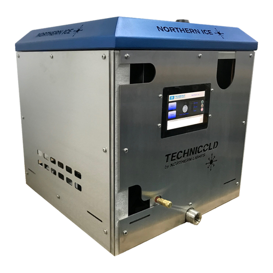
- Page 1 OPERATOR’S MANUAL OPERATOR’S MANUAL OM-NI For Northern Ice www. technicold.com...
- Page 2 Deerfield Beach, FL 33442 Tel: (954) 421-1717 Fax: (954) 421-1712 Copyright ©2020, Northern Lights, Inc. All rights reserved. Northern Lights, Technicold, the Northern Lights logo, and the Technicold logo are trademarks of Northern Lights, Inc. Printed in U.S.A. PART NO.: OM-NI 2/20...
-
Page 3: Table Of Contents
This publication is the property of Northern Lights, Inc. It may not be reproduced in whole or in part without the written permission of Northern Lights, Inc. © Northern Lights, Inc. All rights reserved. Litho U.S.A. Publication number OM-NI 2/2020... -
Page 4: Shipping & Packaging
Shipping & Packaging After uncrating and removing all packing material, inspect Check your paperwork to ensure you have the correct the equipment for concealed shipping damage. Inspect all model unit and that the power supply is correct. Inventory all items on the pack-slip and notify Northern-Lights, Inc freight upon delivery. -
Page 5: Introduction
Introduction Equipment Overview The fresh water is regulated into the evaporator where it freezes on the walls. The Auger motor rotates the auger to scrape the ice build-up off the walls. The harvested ice is Your ice machine consists of several main components. The compacted and pushed towards the auger outlet. - Page 6 Introduction Specifications Power Supply • 230/1/60 Minimum Wire Size 16 AWG Max. Breaker Size 10A • 220/1/50 Minimum Wire Size 16 AWG Max. Breaker Size 10A • 115/1/60 Minimum Wire Size 16 AWG Max. Breaker Size 15A Electrical • Each ice machine requires its own dedicated power supply connected to a breaker. •...
- Page 7 Introduction Pump size. 4.13”L x 4.87”W x 6.11”H (104.9mm x 123.7mm x 155.2mm). • Pump NPT sizes. Outlet. 1/4-18 MPT Inlet. 3/4-14 MPT or 3/8-18 FPT. MTG. QTY 4 0.20in 1.88in 2.72in 48mm 69mm 1.28in 1/4"-18 NPT OUTLET 32mm FRONT SIDE 3/4"-14 3/8"-18...
-
Page 8: Safety Rules
Safety Rules SAFETY AND HAZARD WARNINGS IMPORTANT SAFETY INSTRUCTIONS. CAUTION READ AND FOLLOW ALL SAFETY INSTRUCTIONS IN THIS MANUAL, PRIOR TO THE INSTALLATION IMPORTANT OF ANY GENERATOR SET OR ACCESSORY. KEEP DO NOT REMOVE THE FRONT COVER WITHOUT THESE INSTRUCTIONS FOR FUTURE REFERENCE. FIRST DISCONNECTING THE 3 CABLES/CONNEC- TORS ON THE REAR OF THE DISPLAY. - Page 9 Safety Rules DANGER WARNING Non-Potable Ice High Pressure Refrigerant The ice produced is non-potable and not for human con- The system contains high-pressure refrigerant R404a. The sumption. Do not use in drinks, eat or use in fresh food refrigerant circuit can only be serviced by EPA 608 certified display cases.
-
Page 10: Installation
Installation When handling the unit use gloves and any other safety equipment deemed necessary to prevent bodily injury. You only need to remove two panels for installation, the top cover and the left-hand side panel. Protect surfaces to prevent damage when transporting equipment onboard and during installation. - Page 11 FAN MODE Installation The left-side panel provides access to the condenser coil connections. If for some reason you need to remove the front panel, access to the display connections are through this panel (Figure 5, below). Fig. 5: Condenser coil access 1/2"...
- Page 12 Installation The pump and strainer should accessible for maintenance When connecting fittings to the pump inlet and outlet use and service, not in a location where they can be stepped Teflon tape or other type of pipe sealant. on or damaged. Hand tight is sufficient, DO NOT OVER-TIGHTEN.
- Page 13 Installation Support the ice delivery hose every 12” (31cm). For best performance, install the ice delivery hose on a steady incline from the unit to the ice bin. Limit the amount of bends and dips in the hose. If a bend is unavoidable then the bend radius should be greater than 12”...
- Page 14 Installation Mount the bin full sensor within 3” (7.6 cm) of the outlet The power and sensor wires connect to the terminal of the hose at the 4 o’clock or 8 o’clock position (Figure blocks inside of the electrical enclosure, and to the circuit 11, below) Do not mount directly under the hose outlet.
-
Page 15: Pre-Commissioning Checks
Commissioning PRE-COMMISSIONING CHECKS COMMISSIONING • Check that all electrical connections are on the Start-Up Procedure correct terminals before applying power. Turn on the circuit breaker in the ship’s panel. • Verify the correct voltage into the circuit breaker prior to turning on. Turn on the on/off breaker on the outside of the ice machine’s electrical box. -
Page 16: Display Screen
Display Screen TOUCH SCREEN DISPLAY On the Status screen there are indicators for sensor status, system operation and fault conditions. To the right of the The MAIN screen appears after power is applied and Compressor, Auger and Raw Water Pump is a readout of boot-up. -
Page 17: Troubleshooting
Troubleshooting FAULT REMEDY Compressor Overload Compressor amperage high. Check raw water circuit for restriction. Auger Overload Auger amperage high. Check ice delivery hose for blockage. Raw Water Pump Overload Pump amperage high. Check raw water circuit for restriction. Discharge Pressure Discharge pressure high. -
Page 18: Maintenance
Maintenance DAILY • Raw Water Strainer QUARTERLY Raw water strainers are mandatory for all systems. Check the raw water strainer daily. A visual inspection • Condensate Drains through the sight-glass housing is usually sufficient for Pour a quart of water into the condensate pans. If it does daily inspections. - Page 19 Maintenance YEARLY Follow all directions and warnings provided by the manu- facturer of the chemical. Safety equipment and clothing • Condenser Coils must be used to protect personnel and prevent damage to Back flush condenser coils annually, or more frequently the surrounding area or equipment.
- Page 20 Maintenance Condenser Coil & Raw Water System Cleaning Every chemical manufacturer provides dilution ratios and (continued) gallons of chemical required for the size system that you There are two methods used for cleaning a system. The have. They also have recommended cleaning times for "Immersion Method"...
-
Page 21: Maintenance Log
Maintenance Log TASK NOTES Date OM-NI 2/20... -
Page 22: Wiring Diagrams
Wiring Diagram OM-NI 2/20... -
Page 23: Warranty
The Limited Warranty applies to the following product lines: TECHNICOLD Air Conditioning and Refrigeration Products Technicold manufacturerer NORTHERN LIGHTS, INC. (herein “NLI”) extends to the purchaser and user (herein “Owner”) of the product the following limited warranty (herein “Warranty”). Please read it carefully. - Page 24 Notes Date OM-NI 2/20...
- Page 25 OM-NI 2/20...
- Page 26 Technicold by Northern Lights 1419 W. Newport Center Drive • Deerfield Beach, FL 33442 Tel: (954) 421-1717 • www.technicold.com Northern Lights and Technicold are registered trademarks of Northern Lights, Inc. © 2020 All rights reserved. Litho USA.
Need help?
Do you have a question about the TECHNICOLD OM-NI and is the answer not in the manual?
Questions and answers