
Related Manuals for Northern Lights M80A13S


Summary of Contents for Northern Lights M80A13S
- Page 1 OPERATOR’S MANUAL OPERATOR’S MANUAL OM3-80 For Models: M80A13S, M80A13, M99A13S, M99A13, M150A13S & M150A13 www.northern-lights.com...
- Page 2 4420 14th Avenue NW Seattle, WA 98107 Tel: (206) 789-3880 Fax: (206) 782-5455 Copyright ©2021 Northern Lights, Inc. All rights reserved. Northern Lights™, and the Northern Lights logo are trademarks of Northern Lights, Inc. Printed in U.S.A. PART NO.: OM3-80 12/21...
-
Page 3: Table Of Contents
This publication is the property of Northern Lights, Inc. It may not be reproduced in whole or in part without the written permission of Northern Lights, Inc. © Northern Lights, Inc. All rights reserved. Litho U.S.A. Publication number OM3-80 12/21... -
Page 4: Introduction
Marathon generator end, 150 kW at 1800 rpm. Stamford generator end, 150 kW at 1800 rpm. Serial Numberss When referencing Northern Lights equipment by serial number, please refer only to the number stamped on the Northern Lights serial number plate. ®... -
Page 5: Warranty
For replacement signs, ALWAYS STOP ENGINE proper placement of safety signs or clarification on any BEFORE FUELING safety issue, consult your Northern Lights dealer or the MACHINE. Always fill factory. portable fuel tank outdoors. There can be additional safety information contained Never fuel a hot engine. - Page 6 Safety Rules (Continued) Prevent accidental discharge of starting fluids by Operating equipment requires the full attention of storing all cans in a cool, safe place, away from sparks the operator. Do not use radio or music headphones or open flame. Store with cap securely on container. while operating machinery.
- Page 7 Among the potentially hazardous with a metal object. Use a volt-meter or hydrometer. chemicals that may be used with Northern Lights Frozen batteries may explode if charged. Never products are lubricants, charge a battery that has not been allowed to warm to at least 16 o C (60 o F).
- Page 8 Slowly loosen cap to relieve pressure before and use appropriate equipment exactly as recommended. opening fully. Contact your Northern Lights dealer or Northern Lights factory for MSDS’s used on Northern Lights products. Avoid High Pressure Fluids WARNING...
- Page 9 Exhaust parts and streams can reach high Follow all recommended removal and installation temperatures during operation, leading to burns or procedures in this and associated Northern Lights other serious injury. manuals. Cleaning exhaust filters can also lead to exposure to...
-
Page 10: Lockout / Tag Out Procedures
Scope During maintenance, repairs or retooling of a Northern Lights generator set, simply turning the machine off or unplugging it while it is being worked on does not give enough protection to others who are not performing the maintenance or repair. - Page 11 Notes OM3-80 12/21...
-
Page 12: Component Locations
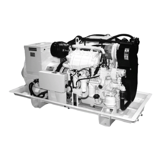
Component Locations M80A13 (Shown with optional equipment) 1. AC Junction Box 6. Lube Oil Dipstick 11. Fuel Injection Lines 2. Air Cleaner 7. Lube Oil Filter 12. Starter 3. Coolant Fill 8. Lube Oil Fill 13. Thermostat Cover 4. Alternator 9. -
Page 13: Control Panels Series 3B
Northern Lights Control Panels 1. SHUTDOWN BYPASS SWITCH This switch bypasses the safety shutdown feature during the starting process. 2. ENGINE CONTROL SWITCH To start the engine, hold this switch in the START position until the engine is running. NOTE: Excessive cranking of marine sets equipped with water lift muffler systems can cause engine damage. -
Page 14: Operating Procedures
Emission-Related Installation & Instructions Failing to follow these instructions when installing a turbocharged engine and 48” (1200 mm) for a non- a certified engine in a vessel violates federal law (40 turbocharged unit, measured at the engine exhaust elbow. CFR 1068.105(b)), subject to fines or other penalties as described in the Clean Air Act. -
Page 15: Shutdowns And Alarms
If the oil level was normal, DO NOT restart the engine. Call your Northern Lights or Lugger dealer for assistance. OM3-80 12/21... -
Page 16: Engine Operation
In these situations, an additional 100 hour break-in period is situations, an additional 100 hour break-in period is recommended using a new change of engine break in oil and a recommended using a new change of Northern Lights new Northern Lights oil filter. Northern Lights... - Page 17 Engine Operation (Continued) IMPORTANT: DO NOT fill above the crosshatch pattern IMPORTANT: DO NOT add makeup oil until the oil RG8028A —UN—15JAN99 Do not add makeup oil until the oil level is BELOW the of the engine oil dipstick or the FULL level is BELOW the ADD mark on dipstick.
-
Page 18: Engaging & Disengaging Front Pto (If Equipped)
Engine Operation (Continued) 7. Check poly-vee belt for proper alignment and seating in pulley grooves. Two zinc plugs (A) are installed in the sea water cooling system to help neutralize the corrosive action of salt water on internal cavities of marine engine components. -
Page 19: Using A Booster Battery Or Charger
Engine Operation (Continued) Using a Booster Battery or Charger A 12-volt booster battery can be connected in parallel with battery(ies) on the unit to aid in cold weather starting. ALWAYS use heavy duty jumper cables. CAUTION: Gas given off by battery is explosive. Before connecting or disconnecting a battery charger, turn charger off. -
Page 20: Welding Near Electronic Control Units
Engine Operation (Continued) Welding Near Electronic Control Units IMPORTANT: Do not jump-start engines with arc welding equipment. Currents and voltages are too high and may cause permanent damage. 1. Disconnect the negative (-) battery cable(s). 2. Disconnect the positive (+) battery cable(s). 3. - Page 21 Notes OM3-80 12/21...
-
Page 22: Propulsion And Prime Power Units
Lubrication and Maintenance Lubrication and Maintenance Service Interval Chart—Propulsion and Prime Power Units Lubrication and Maintenance Service Intervals Daily/Before 250 Hour/6 500 Hour/12 2000 Hour/24 Service As Item Every Startup Month Month Month Required • Check Engine Oil Level and Coolant Level •... -
Page 23: Standby Generator Sets
Lubrication and Maintenance (Continued) Lubrication and Maintenance Service Interval Chart—Standby Generator Sets Lubrication and Maintenance Service Intervals Daily/Before 250 Hour/6 500 Hour/12 2000 Hour/24 Service As Item Every Startup Month Month Month Required Operate Engine at Rated Speed and 50%—70% Load for a Minimum of 30 Minutes. -
Page 24: Daily Prestarting Checks
Lubrication & Maintenance/Daily Daily Prestarting Checks Do the following BEFORE STARTING THE ENGINE for IMPORTANT: DO NOT add makeup oil until the oil level is BELOW the add mark. cap (B) may be located on either the left or the right side of engine. - Page 25 Lubrication & Maintenance/Daily (Continued) High-Pressure Fluids A—Engine Top Tank Engine Top Tank RG19661,00003D3 -19-29JAN13-2/4 IMPORTANT: A restricted or clogged sea water strainer will result in hotter than normal (or overheated) engine coolant and marine gear oil temperatures. 3. The sea water strainer should be checked daily and cleaned as required, depending upon the operating environment.
- Page 26 Lubrication & Maintenance/Daily (Continued) 4. If equipped with air intake restriction indicator gauge (A), check gauge to determine if air cleaner needs to be serviced. The reset button will pop up when air cleaner needs to be serviced. IMPORTANT: Maximum air intake restriction is 625 mm (25 in.
-
Page 27: Hour/6 Month
chance of system contamination. Excessive coolant leakage may indicate the need to Inspect: replace the water pump seal. Contact your engine • Engine shields and guards for trash build-up. distributor or servicing dealer for repairs. • Air intake system hoses and connections for cracks and loose clamps. - Page 28 IMPORTANT: Filtration of oils is critical to Northern Lights Oil Filter 6. Wipe both sealing surfaces of the header (D, E) with a clean rag. Ensure that the notches in dust seal (F) are properly installed in the slots of the housing.
- Page 29 Lubrication & Maintenance/250 Hour/6 Month (Continued) Servicing Battery CAUTION: Battery gas can explode. Keep sparks to check battery electrolyte level. Never check battery charge by placing a metal object across the posts. Use a voltmeter or hydrometer. Always remove grounded NEGATIVE (–) battery WARNING: Battery posts, terminals, and related Exploding Battery accessories contain lead and lead compounds, chemicals...
- Page 30 Lubrication & Maintenance/250 Hour/6 Month (Continued) CAUTION: Sulfuric acid in battery electrolyte is poisonous. It is strong enough to burn skin, eat holes in clothing, and cause blindness if splashed into eyes. Avoid the hazard by: 1. Filling batteries in a well-ventilated area. 2.
- Page 31 Lubrication & Maintenance/250 Hour/6 Month (Continued) Inspect and Replacing Zinc Plugs Two zinc plugs (A) are installed in the sea water cooling system to help reduce the corrosive action of salt in the sea water. The reaction of the zinc to sea water causes the plugs to deteriorate, instead of the more critical cooling system parts.
- Page 32 Lubrication & Maintenance/250 Hour/6 Month (Continued) Checking Belt Wear 1. Remove belt guard (A). 2. Swing tensioner arm (C) to remove all belt slack. 3. Remove and inspect belt for cracks, fraying, or stretched-out areas. Replace if necessary. NOTE: While belt is removed, inspect pulleys and bearings.
-
Page 33: Hour/12 Month
Lubrication & Maintenance/500 Hour/12 Month Replace Crankcase Vent Filter 1. Remove screws (A) and remove the crankcase vent lid. into place. 4. Install lid and lock down screws. A—Screws Replace Crankcase Vent Filter RG19661,00003D8 -19-13FEB13-1/1 Checking Closed Crankcase Vent System 1. - Page 34 Lubrication & Maintenance/500 Hour/12 Month (Continued) Replace Fuel Filter penetrate the skin causing serious injury. Relieve pressure before disconnecting fuel or other lines. Tighten all connections before applying pressure. Keep hands and body away from pinholes and Use a piece of cardboard or paper to search for leaks.
- Page 35 Lubrication & Maintenance/500 Hour/12 Month (Continued) Replacing Fuel Filter/Water Separator penetrate the skin causing serious injury. Relieve pressure before disconnecting fuel or other lines. Tighten all connections before applying pressure. Keep hands and body away from pinholes and Use a piece of cardboard or paper to search for leaks.
- Page 36 Lubrication & Maintenance/500 Hour/12 Month (Continued) Checking Belt Tensioner Spring Tension and Belt Wear (Automatic Tensioner) Belt drive systems equipped with automatic (spring) belt tensioners cannot be adjusted or repaired. The automatic belt tensioner is designed to maintain proper belt tension over the life of the belt.
- Page 37 Lubrication & Maintenance/500 Hour/12 Month (Continued) Checking Cooling System pressurized cooling system can cause serious burns. cool enough to touch with bare hands. Slowly before removing completely. IMPORTANT: Air must be expelled from cooling High-Pressure Fluids of cylinder head or plug in thermostat 2.
- Page 38 Lubrication & Maintenance/500 Hour/12 Month (Continued) Replenishing Supplemental Coolant Additives (SCAs) Between Coolant Changes IMPORTANT: Do not add supplemental coolant additives when the cooling system is drained contain SCAs, the coolant must be precharged. Determine the total system capacity and premix with 3% John Deere Coolant Conditioner.
- Page 39 Lubrication & Maintenance/500 Hour/12 Month (Continued) Testing Diesel Engine Coolant Maintaining adequate concentrations of glycol and Compare the results to the supplemental coolant additive inhibiting additives in the coolant is critical to protect the (SCA) chart to determine the amount of inhibiting additives engine and cooling system against freezing, corrosion, in your coolant and whether more John Deere COOLANT and cylinder liner erosion and pitting.
- Page 40 Lubrication & Maintenance/500 Hour/12 Month (Continued) On All Engines: NOTE: The heat exchanger core may be removed from housing when either end cap is removed. It is strongly recommended that both end caps be removed for cleaning when cleaning the heat exchanger core. 5.
- Page 41 Lubrication & Maintenance/500 Hour/12 Month (Continued) 1. Insert two O-rings into front and rear end caps. 2. Lubricate ends of tube bundle lightly with clean multi-purpose grease. NOTE: For proper orientation of the tube bundle, the core divider plate must be in line with inlet end cap divider slot with arrow pointing in the correct direction.
- Page 42 Lubrication & Maintenance/500 Hour/12 Month (Continued) Remove, Inspect and Clean Engine Aftercooler Core IMPORTANT: Initially remove and inspect the aftercooler core at 250 hour or three month service interval on a new engine. Then, remove and clean at every 500 hour or 12 month interval thereafter.
- Page 43 Lubrication & Maintenance/500 Hour/12 Month (Continued) Pressure Testing Cooling System 1. Allow engine to cool, then carefully remove coolant pressurized cooling system can cause serious burns. 2. Fill tank with coolant to the normal operating level. IMPORTANT: DO NOT apply excessive pressure cool enough to touch with bare hands.
-
Page 44: 2000 Hour/24 Month
Lubrication & Maintenance/2000 Hour/24 Month Remove, Inspect and Clean Engine Aftercooler Core IMPORTANT: Initially remove and inspect the aftercooler core at 250 hour or three month service interval on a new engine. Then, remove and clean at every 500 hour or 12 month interval thereafter. - Page 45 Lubrication & Maintenance/2000 Hour/24 Month (Continued) 4-Cylinder Engine NOTE: Firing order is 1-3-4-2. Lock No. 1 piston at TDC compression stroke (B). Adjust valve clearance on No. 1 and 3 exhaust valves and No. 1 and 2 intake valves. compression stroke (C). Adjust valve clearance on No.
- Page 46 Lubrication & Maintenance/2000 Hour/24 Month (Continued) 3. Open engine block drain valve (A) on left side of engine. Drain all coolant from engine block. 4. Open heat exchanger or top tank drain valve. Drain all coolant from heat exchanger or top tank. 5.
- Page 47 Lubrication & Maintenance/2000 Hour/24 Month (Continued) Remove Thermostats pressurized cooling system can cause serious burns. cool enough to touch with bare hands. Slowly removing completely. DO NOT drain coolant until it has reached ambient temperature. 1. Visually inspect area around thermostat housing and cover for leaks.
- Page 48 Lubrication & Maintenance/2000 Hour/24 Month (Continued) Inspecting Thermostats and Testing Opening Temperature 1. Remove thermostats. (See REMOVING THERMOSTATS earlier in this section.) 2. Visually inspect thermostats for corrosion or damage. Replace thermostats as a matched set as necessary. 3. Inspect thermostat with wiggle wire in vent notch. If wire movement is restricted, replace thermostat if cleaning does not free movement.
- Page 49 Lubrication & Maintenance/2000 Hour/24 Month (Continued) Remove and Inspect Impeller 1. Close sea cock and drain sea water system if not previously done. 2. Remove six cover plate cap screws with washers and remove cover plate (A) with O-ring. Remove impeller end cap from end of impeller bore.
- Page 50 material missing. Impellers that are run dry will overheat and fail the impeller blades at the root. Impellers that swell and stick, fail the impeller in the middle of the blade. If impeller replacement is necessary, order an impeller Inspect Sea Water Pump Impeller repair kit.
- Page 51 Lubrication & Maintenance/2000 Hour/24 Month (Continued) Inspect And Repair Raw Water Pump NOTE: Sea water pump with shaft key is illustrated. Sea water pumps with a splined shaft follow the same procedure 1. Close sea cocks and drain raw water system. 2.
-
Page 52: Service As Required
Service As Required Additional Service Information This is not a detailed service manual. If you want more detailed service information, use the form in the back of this manual to order a component technical manual. RG,RG34710,5591 -19-20MAY96-1/1 Do Not Modify Fuel System pump (arrow), the injection pump timing, or the fuel injectors in ways not recommended by the manufacturer will terminate the warranty... - Page 53 Service As Required (Continued) Adding Coolant pressurized cooling system can cause serious burns. cool enough to touch with bare hands. Slowly before removing completely. IMPORTANT: Never pour cold liquid into a hot engine, as it may crack cylinder head or block.
- Page 54 Service As Required (Continued) Servicing Air Cleaner Filter Element IMPORTANT: Always service primary air cleaner element when air restriction indicator shows a vacuum of 625 mm (25 in.) H O, or when reset button has popped up (6068SFM75/AFM75 only). Also replace element if it is torn, or visibly dirty. NOTE: This procedure applies to John Deere air cleaner kits.
- Page 55 Service As Required (Continued) IMPORTANT: Let element dry at room temperature. rubber base or end cap. 6. Shake off excess water and let the element dry at room temperature. being oiled with oil provided in kit RE504585. motor oil, diesel fuel, or any type light-weight spray lubricant.
- Page 56 Service As Required (Continued) IMPORTANT: Whenever the air cleaner has been serviced, ALWAYS fully depress the air restriction indicator reset button (if equipped) to assure accurate readings. If equipped, fully depress air restriction indicator reset button (A) and release to reset indicator. Air Restriction Indicator Reset Button OUOD006,0000098 -19-10DEC09-5/5 Replacing Air Cleaner Filter Element...
- Page 57 Service As Required (Continued) Replacing Alternator Belt (With Automatic Tensioner) Refer to CHECKING BELT TENSIONER SPRING TENSION AND BELT WEAR in Lubrication and Maintenance/500 Hour/12 Month Section for additional information on the belt tensioner. CAUTION: Belt guard should be in place at all times when engine is running.
- Page 58 Service As Required (Continued) Check Front Power Take-Off (PTO) CAUTION: Entanglement in rotating driveline can cause serious injury or death. Keep shield on PTO driveshaft between clutch housing and the engine driven equipment at all times during Stop the engine and be sure PTO driveline is stopped before making adjustments.
- Page 59 Service As Required (Continued) Bleeding Fuel System lines can cause serious injury. Do not disconnect or attempt repair of fuel lines, sensors, or any other components between the high-pressure fuel pump and nozzles on engines with High Pressure Common Rail (HPCR) fuel system. Only technicians familiar with this type of system can perform repairs.
- Page 60 Service As Required (Continued) Remove And Install Sea Water Pump (4045AFM85/6068AFM85) 1. Close sea cock and drain sea water system. 2. Remove sea water outlet connection (A), remove sea water pump cap screws (B) and remove pump. 3. Clean all gasket material from both mating surfaces. 4.
-
Page 61: Troubleshooting
Troubleshooting General Troubleshooting Information wiring diagrams are provided in this section to help isolate electrical problems on engines using John Deere wiring harness and instrument (gauge) panel. Later in this section is a list of possible engine problems that may be encountered, accompanied by possible causes and corrections. -
Page 62: Precautions For Welding
Troubleshooting (Continued) Precautions for Welding Remove paint before welding or heating (see Safety Section in this manual for more information on paint removal and high-pressure lines). CAUTION: Avoid potentially toxic fumes and dust. Hazardous fumes can be generated when paint is heated by welding, soldering, or using a torch. -
Page 63: Ec Engine Electrical System Layout
Troubleshooting (Continued) Electronically Controlled Engine Electrical System Layout 1— Engine Control Unit (ECU) 9— Fuel Temperature Sensor 16— Crankshaft Position Sensor 25— ECU Fuse (20 Amp) 2— Auxiliary Power Connector Connector Connector 26— Transient Voltage Protection 3— Coolant Temperature Sensor 10—... -
Page 64: Wiring Diagrams
Troubleshooting (Continued) 4045TFM85 Marine Electronic Control System Wiring Diagram 4.5L Engine MATING VIEW OF RAIL PRESSURE RAIL PRESSURE CONNECTOR INCREASE PRESSURE J1-B4 J1-D4 J1-A4 J1-E4 J1-E3 J1-D3 J1-E2 FOCUS 16 4.5L 4 VALVE ENGINE CONTROL UNIT (ECU) 32 POSITION - BLACK 48 POSITION - BROWN 32 POSITION - BLUE J2-L2... - Page 65 5050 5050 - FOCUS 16 (ECU) Troubleshooting (Continued) RG19661,00003EA -19-21FEB13-1/2 A— Focus 16, 4.5 L, 4 Valve, J2— 48 Position - Brown J1-D3— Excitation Voltage #1 X01— Crankshaft Position Engine Control Unit (ECU) J1-D4— Return J3— 32 Position - Blue Sensor B—...
- Page 66 Troubleshooting (Continued) 4045TFM85 Marine Electronic Control System Wiring Diagram - Cont-d PRESSURE COOLANT FUEL MANIFOLD SENSOR (CLEAN SIDE) TEMP TEMP AIR TEMP INCREASE PRESSURE WATER IN FUEL J1-D2 J1-C4 J1-F4 J1-C2 J1-A3 J1-F3 FOCUS 16 4.5L 4 VALVE ENGINE CONTROL UNIT (ECU) 32 POSITION - BLACK 48 POSITION - BROWN 32 POSITION - BLUE...
- Page 67 Troubleshooting (Continued) A— Focus 16, 4.5 L, 4 Valve, C08-R— PWM Throttle J1-F4— Analog 2 Engine Control Unit (ECU) Switch C08-S— Air Filter Restriction J2— 48 Position - Brown C08— Auxiliary Connector C08-J— External Derate J3— 32 Position - Blue C08-A—...
- Page 68 Troubleshooting (Continued) 4045TFM85 Marine Electronic Control System Wiring Diagram - Cont-d 12V / 24V PCV 1 4.5L Engine FUEL INJECTORS 5410 5410 J1-G1 J1-E1 J1-C1 J1-G2 J1-F1 J1-D1 J1-H2 J1-H1 J1-F2 FOCUS 16 4.5L 4 VALVE ENGINE CONTROL UNIT (ECU) 32 POSITION - BLACK 48 POSITION - BROWN 32 POSITION - BLUE...
- Page 69 Troubleshooting (Continued) A— Focus 16, 4.5 L, 4 Valve, C09-H— Warning Lamp C09-T— Resume Coast/Bump J1-H1— High Driver Engine Control Unit (ECU) C09-J— Accessory Down J1-H2— Low Driver C01— Fuel Injectors C09-K— Tachometer C09-U— CAN Low J2— 48 Position - Brown C09-A—...
- Page 70 Troubleshooting (Continued) 4045TFM85 Marine Electronic Control System Wiring Diagram - Cont-d + AUX 5082 BATT TERM 5032 - AUX BATT TERM COIL STARTER RELAY 12V OR 24V COIL (12V OR 24V) START MOTOR SINGLE REMOTE ON/OFF POINT PLUG GROUND 5050 SPG -ENGINE START COMPONENTS FOCUS 16 4.5L 4 VALVE ENGINE CONTROL UNIT (ECU) 32 POSITION - BLACK...
- Page 71 Troubleshooting (Continued) A— Focus 16, 4.5 L, 4 Valve, C11— Diagnostic Connector C16— Battery J2-B1— CAN Low Engine Control Unit (ECU) C12— Transient Voltage C17— Single Point Ground J3— 32 Position - Blue C06— Wiring Supplied With JD Protection (12 V or 24 V) G1—...
- Page 72 Troubleshooting (Continued) 4045AFM85 Marine Electronic Control System Wiring Diagram 4.5L Engine Y5004 MANIFOLD AIR PRESSURE MANIFOLD TRANSFER PUMP SENSOR AIR TEMP MATING VIEW OF RAIL PRESSURE INCREASE RAIL PRESSURE CONNECTOR PRESSURE INCREASE PRESSURE J3-F4 J3-F3 J3-G4 J3-G3 J3-F1 J3-B2 J3-C4 J3-A2 J3-C1 J3-G1...
- Page 73 Troubleshooting (Continued) A— Focus 14, 4.5 L, 4 Valve, C05-04— Sensor Excitation (+5 V) J3-F1— Analog 15 T02— Manifold Air Temperature Engine Control Unit (ECU) C05-05— Sensor Return J3-F3— Return Sensor B— Mating View of Rail Pressure C05-06— Exhaust Temperature J3-G1—...
- Page 74 Troubleshooting (Continued) 4045AFM85 Marine Electronic Control System Wiring Diagram - Cont’d FUEL PRESSURE PRESSURE COOLANT FUEL SENSOR SENSOR (CLEAN SIDE) TEMP TEMP INCREASE INCREASE PRESSURE PRESSURE J3-H3 J3-D3 J3-B1 J3-C2 J3-C3 J3-H4 FOCUS 14 4.5L 4 VALVE ENGINE CONTROL UNIT (ECU) 32 POSITION - BLACK 48 POSITION - BROWN 32 POSITION - BLUE...
- Page 75 Troubleshooting (Continued) A— Focus 14, 4.5 L, 4 Valve, C08-J— External Derate C08-U— Throttle Station Three J3-H4— Excitation Voltage #2 Engine Control Unit (ECU) C08-K— External Shutdown Lamp P03— Fuel Rail Pressure Sensor C08— Auxiliary Connector C08-V— Engine Sync Lamp P04—...
- Page 76 Troubleshooting (Continued) 4045AFM85 Marine Electronic Control System Wiring Diagram - Cont’d PCV 1 4.5L Engine FUEL INJECTORS 5410 5410 J1-G1 J1-E1 J1-C1 J1-G2 J1-F1 J1-D1 J1-D3 J1-H2 J1-H1 FOCUS 14 4.5L 4 VALVE ENGINE CONTROL UNIT (ECU) 32 POSITION - BLACK 48 POSITION - BROWN 32 POSITION - BLUE 5714...
- Page 77 Troubleshooting (Continued) A— Focus 14, 4.5 L, 4 Valve, C09-R— Digital Throttle J1-E1— Cylinder 1 Engine Control Unit (ECU) urable Output/Kick Back C09-S— Sensor Return J1-F1— Cylinder 3 C01— Fuel Injectors Start C09-T— Resume Coast/Bump J1-H1— High Driver C09-A— Wait To Start C09-J—...
- Page 78 Troubleshooting (Continued) 4045AFM85 Marine Electronic Control System Wiring Diagram - Cont’d + AUX 5082 BATT TERM 5032 - AUX BATT TERM COIL STARTER RELAY 12V OR 24V COIL (12V OR 24V) START MOTOR SINGLE REMOTE ON/OFF POINT PLUG GROUND 5050 SPG -ENGINE START COMPONENTS FOCUS 14 4.5L 4 VALVE ENGINE CONTROL UNIT (ECU) 32 POSITION - BLACK...
- Page 79 Troubleshooting (Continued) A— Focus 14, 4.5 L, 4 Valve, C11— Diagnostic Connector C16— Battery J2-B1— CAN Low Engine Control Unit (ECU) C12— Transient Voltage C17— Single Point Ground J3— 32 Position - Blue C06— Wiring Supplied With JD Protection (12 V or 24 V) G1—...
-
Page 80: Engine Troubleshooting
Troubleshooting (Continued) Engine Troubleshooting any fault codes on the diagnostic gauge display and NOTE: If using BIODIESEL blends above B20, the perform the corrective actions. (See information possibility of some of the symptoms listed below, later in this section.) If any problems remain, use such as power loss, could increase. - Page 81 Troubleshooting (Continued) Symptom Problem Solution Injection pump out of time. See your authorized servicing dealer or engine distributor. Low coolant temperature. Remove and check thermostat. Engine overheating. See “Engine Overheats”. Engine runs irregularly or stalls Low coolant temperature. Remove and check thermostat. frequently Poor quality fuel.
- Page 82 Troubleshooting (Continued) Symptom Problem Solution Leaking exhaust manifold gasket. See your authorized servicing dealer or engine distributor. Defective aneroid control line. See your authorized servicing dealer or engine distributor. Restricted fuel hose. Clean or replace fuel hose. Low fast idle speed. See your authorized servicing dealer or engine distributor.
- Page 83 Troubleshooting (Continued) Symptom Problem Solution Fuel injectors dirty. Use John Deere approved biodiesel or diesel fuel conditioners containing detergents. If no improvement is seen, see your authorized servicing dealer or engine distributor. Engine out of time. See your authorized servicing dealer or engine distributor.
- Page 84 Troubleshooting (Continued) Symptom Problem Solution Engine overloaded. Reduce load. Improper valve clearance. See your authorized servicing dealer or engine distributor. Injection nozzles dirty. See your authorized servicing dealer or engine distributor. Injector tip deposits Use John Deere approved biodiesel fuel conditioners containing detergents.
-
Page 85: Electrical Troubleshooting
Troubleshooting (Continued) Electrical Troubleshooting Symptom Problem Solution Undercharged electrical system Excessive electrical load from added Remove accessories or install higher output alternator. accessories. Excessive engine idling. Increase engine rpm when heavy electrical load is used. Poor electrical connections on battery, Inspect and clean as necessary. -
Page 86: Diagnostic Trouble Codes
Troubleshooting (Continued) Listing Of Diagnostic Trouble Codes (DTC) Following is a list of SPNs, FMIs, Blink Codes and description of the diagnostic trouble codes that can occur The Diagnostic Trouble Codes (DTCs) are output on the in the various engine systems. Not all of these codes will diagnostic gauge according to the J1939 standard as a be present in all engine applications. - Page 87 Troubleshooting (Continued) Blink Description of Fault Corrective Action Code ....... ECU Power Down Error (Internal ECU Problem) Contact Servicing Dealer ........ Fuel Temperature Signal Extremely High Add Fuel or Switch Fuel Tanks ....... Fuel Temperature Signal Out of Range High Check Sensor and Wiring ..
- Page 88 Troubleshooting (Continued) Blink Description of Fault Corrective Action Code ......Injector Number 2 Part Number Calibration Fault Contact Servicing Dealer ....... Injector Number 3 Part Number Data Invalid Contact Servicing Dealer ......Injector Number 3 Circuit Has High Resistance Check Injector Wiring or Injector Solenoid ..
- Page 89 Troubleshooting (Continued) Blink Description of Fault Corrective Action Code ..........Sensor Supply 1 Voltage High Check Wiring ............. Sensor Supply 1 Voltage Low Check Wiring ............ Sensor Supply 2 Voltage High Check Wiring ..
-
Page 90: Intermittent Fault Diagnostics
Troubleshooting (Continued) Intermittent Fault Diagnostics Intermittent faults are problems that periodically “go away”. If the problem is intermittent, try to reproduce the operating A problem such as a terminal that intermittently doesn't conditions that were present when the Diagnostic Trouble make contact can cause an intermittent fault. -
Page 91: Storage
Troubleshooting (Continued) 3. Once "Utilities" is highlighted, press "Enter" to activate the utilities function. Select Utilities OURGP11,00000E3 -19-29SEP03-3/4 4. Scroll to the "Software Version". Press "Enter" to view the software version. Press the menu button twice to return to the main menu. Software Version OURGP11,00000E3 -19-29SEP03-4/4 Storage... - Page 92 Storage (Continued) Preparing Engine for Long Term Storage The following storage preparations are used for long term 5. Prepare a tank with a solution of diesel fuel and rust engine storage up to one year. After that, the engine preventive oil, at ten (10) ounces of rust preventive oil should be started, warmed up, and retreated for an per gallon of diesel fuel.
- Page 93 Storage (Continued) Removing Engine from Long-Term Storage Refer to the appropriate section for detailed services listed below or have your authorized servicing dealer or clean fuel and bleed the fuel system. (See BLEEDING engine distributor perform services that you may not be THE FUEL SYSTEM in Service as Required Section.) familiar with.
-
Page 94: Specifications
Revised 5-4-17 Specifications ITEM UNIT OF MEASURE ENGINE MODEL M80A13 General Data Engine Type In-line, 4 cycle diesel Aspiration Turbocharged and coolant after cooled Number of Cylinders Bore mm (in.) 106 (4.17) Stroke mm (in.) 127 (5.00) Displacement L (cu in.) 4.5 (275) Combustion System Direct Injection... - Page 96 4420 14th Ave. NW., Seattle WA 98107 Tel: (206) 789-3880 • 1-800-762-0165 • www.northern-lights.com Northern Lights and Lugger are registered trademarks of Northern Lights, Inc. © 2021 All rights reserved. Litho USA.
Need help?
Do you have a question about the M80A13S and is the answer not in the manual?
Questions and answers