Wintex Agro 1000 Workshop Manual
Hide thumbs
Also See for 1000:
- Instruction manual (9 pages) ,
- Operating instructions manual (8 pages) ,
- Instruction manual (24 pages)
Advertisement
Quick Links
P A G E
| 1
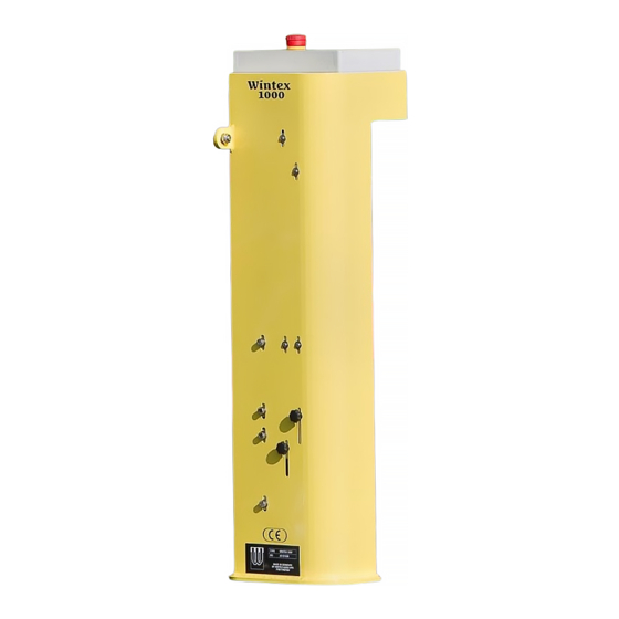
WORKSHOP MANUAL WINTEX 1000
0-25 cm
Fully automatic
Fast and efficient
Optimum speed
Minimum maintenance
Reliable
Competitive
Wintex Agro, Vilhelmsborgvej 15, DK-7700 Thisted
+45 97990800, contact@wintexagro.com, www.wintexagro.com
201605
Advertisement

Related Manuals for Wintex Agro 1000


Summary of Contents for Wintex Agro 1000
- Page 1 P A G E WORKSHOP MANUAL WINTEX 1000 0-25 cm Fully automatic Fast and efficient Optimum speed Minimum maintenance Reliable Competitive Wintex Agro, Vilhelmsborgvej 15, DK-7700 Thisted +45 97990800, contact@wintexagro.com, www.wintexagro.com 201605...
-
Page 2: Workshop Manual
WINTEX trained Technician. Repairs to such items should NEVER be attempted PLEASE NOTE: by untrained individuals. All numbers in ( ) are for the WINTEX 1000 with a 21 mm probe. Wintex Agro, Vilhelmsborgvej 15, DK-7700 Thisted +45 97990800, contact@wintexagro.com, www.wintexagro.com... - Page 3 PREPERATION Cleaning It is essential that the WINTEX 1000 is thoroughly cleaned using a steam cleaner or de-greaser prior to work commencing. This will enhance the ability to assess the serviceability of the machine and identify any necessary repairs. Positioning The soil sampler should be supported in such a way as to prevent it falling and provide a stable platform to work from.
- Page 4 The stop can now be removed. Refit Reverse steps 1-3 as above ensuring the soil box being at the correct side of the stop. Apply medium strength thread lock solution to threads. Wintex Agro, Vilhelmsborgvej 15, DK-7700 Thisted +45 97990800, contact@wintexagro.com, www.wintexagro.com...
- Page 5 Using the Wintex special key hold the bearing in position and loosen the 10 mm locking nut. Rotate the bearing spanner to adjust the bearing to the correct position and then lock it in position using the 10 mm locking nut. Eccentric bearing M10 cap bolt Torsion spring M12 cap bolt Wintex Agro, Vilhelmsborgvej 15, DK-7700 Thisted +45 97990800, contact@wintexagro.com, www.wintexagro.com...
- Page 6 Locate the top of the ejector top and the two 17 mm (19 mm) nuts holding it in position. Using two 17 mm (19 mm) spanners undo the top locking nut using the second spanner to prevent the lower nut from rotating. 17 mm (19 mm) nut Wintex Agro, Vilhelmsborgvej 15, DK-7700 Thisted +45 97990800, contact@wintexagro.com, www.wintexagro.com...
- Page 7 It may be necessary during installing of a new probe to clean the threads on the inside of the drilling hub. This can be done using a thread cleaner to specification M18x1.5 (M21x1.5) thread pitch. Thread cleaner M18x1.5 (M21x1.5) Wintex Agro, Vilhelmsborgvej 15, DK-7700 Thisted +45 97990800, contact@wintexagro.com, www.wintexagro.com...
- Page 8 P A G E *NOTE: It is important to note that two different size locking collars are in use. Only the 50 mm long version should be used. Any others should be replaced. Wintex Agro, Vilhelmsborgvej 15, DK-7700 Thisted +45 97990800, contact@wintexagro.com, www.wintexagro.com...
- Page 9 Place a 14 mm spanner on the flats of the end of the piston rod, and whilst doing this release the 14 mm nut from the end of the piston rod. Wintex Agro, Vilhelmsborgvej 15, DK-7700 Thisted +45 97990800, contact@wintexagro.com, www.wintexagro.com...
- Page 10 Using two 24 mm spanners undo the M16 bolt holding the drilling head lift / lower chain sprocket from the end of the mast. The drilling head with attached lift / lower chains can now be removed from the mast by sliding it off the end of the mast guide rail. Wintex Agro, Vilhelmsborgvej 15, DK-7700 Thisted +45 97990800, contact@wintexagro.com, www.wintexagro.com...
- Page 11 Sprockets will also require changing if the sprocket has been running on one edge of the bearing as opposed to the centre of it as shown in the photo below. Wintex Agro, Vilhelmsborgvej 15, DK-7700 Thisted +45 97990800, contact@wintexagro.com, www.wintexagro.com...
- Page 12 The top chain block must be attached first. The two top hex screws must be aligned in the centre of the elongated hole on the underside of the chassis. The bottom chain block can then be attached in the same manner. Wintex Agro, Vilhelmsborgvej 15, DK-7700 Thisted +45 97990800, contact@wintexagro.com, www.wintexagro.com...
- Page 13 10. Finally re-attach the piston rod to the mast (as removed in step 1-3). The mast and piston rod must be extended out of the bottom of the chassis to be able to gain access to the threaded end of the piston rod. Wintex Agro, Vilhelmsborgvej 15, DK-7700 Thisted +45 97990800, contact@wintexagro.com, www.wintexagro.com...
- Page 14 Allowing the piston rod some movement reduces the risk of damage occurring. Once the piston has sufficient movement, tighten the 4 mm grub screw in the 14 mm nut using a 2 mm hex key to prevent the nut working loose. Wintex Agro, Vilhelmsborgvej 15, DK-7700 Thisted +45 97990800, contact@wintexagro.com, www.wintexagro.com...
- Page 15 Once the probe is in the correct position, tighten the three M8 x 20 mm hex button head screws first followed by the three 10 mm nyloc nuts on the bottom of the drilling head. Wintex Agro, Vilhelmsborgvej 15, DK-7700 Thisted +45 97990800, contact@wintexagro.com, www.wintexagro.com...
- Page 16 Fit the M8 threaded stud into the ejector tip using a 4 mm hex key. Secure with thread lock. Screw the ejector tip and threaded stud assembly into the ejector rod. Tighten the ejector tip using locking pliers. Wintex Agro, Vilhelmsborgvej 15, DK-7700 Thisted +45 97990800, contact@wintexagro.com, www.wintexagro.com...
- Page 17 Move the ejector rod so that it runs centrally through the drilling head hub and the soil probe. When in the correct position tighten the six hex button head set screws followed by the 10 mm (12 mm) nut on the end of the ejector rod. Wintex Agro, Vilhelmsborgvej 15, DK-7700 Thisted +45 97990800, contact@wintexagro.com, www.wintexagro.com...
- Page 18 Dependent upon whether the ejector tip is protruding too far or too little, adjust the height of the cap screw and lock by tightening the two 13 mm nuts. (Too much protrusion - increase height of set screw.) (Too little protrusion - decrease height of set screw.) Height Limiter Wintex Agro, Vilhelmsborgvej 15, DK-7700 Thisted +45 97990800, contact@wintexagro.com, www.wintexagro.com...
- Page 19 HYDRAULIC SYSTEM The Wintex 1000 utilizes a double acting hydraulic ram, which is housed inside the main chassis of the machine. Oil pressure is supplied and controlled via an electronic solenoid operated directional control valve. This control valve has a manual override in the event of a failure.
Need help?
Do you have a question about the 1000 and is the answer not in the manual?
Questions and answers