Table of Contents
Advertisement
Quick Links
Smart encoders & actuators
SMRA +
MRA
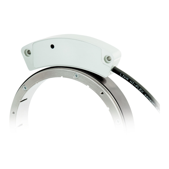
• SMRA bearingless absolute magnetic encoder
• MRA ring, through hollow shaft up to Ø110 mm / 4.33"
• Range of resolutions up to 16,384 cpr
• SSI and BiSS C-mode interfaces with error information
• IP68 protection rate
Suitable for the following models:
SMRA -BG1-...
•
SMRA -BG2-...
•
SMRA -GG1-...
•
SMRA -GG2-...
•
SMRA -SC1-...
•
SMRA -SC2-...
•
Lika Electronic
User's guide
•
Tel. +39 0445 806600
Table of Contents
•
info@lika.biz
10
11
15
18
22
33
34
•
www.lika.biz
7
8
Advertisement
Table of Contents

Related Manuals for IKA SMRA + MRA


Summary of Contents for IKA SMRA + MRA
-
Page 1: Table Of Contents
User's guide Smart encoders & actuators SMRA + • SMRA bearingless absolute magnetic encoder • MRA ring, through hollow shaft up to Ø110 mm / 4.33” • Range of resolutions up to 16,384 cpr • SSI and BiSS C-mode interfaces with error information •... - Page 2 This publication was produced by Lika Electronic s.r.l. 2020. All rights reserved. Tutti i diritti riservati. Alle Rechte vorbehalten. Todos los derechos reservados. Tous droits réservés. This document and information contained herein are the property of Lika Electronic s.r.l. and shall not be reproduced in whole or in part without prior written approval of Lika Electronic s.r.l.
-
Page 3: General Contents
General contents User's guide................................. 1 General contents..............................3 Subject Index............................... 5 Typographic and iconographic conventions....................6 Preliminary information............................ 7 1 - Safety summary............................8 1.1. Safety......................................8 1.2 Electrical safety..................................8 1.3 Mechanical safety..................................9 2 - Identification............................10 3 - Mounting instructions......................... 11 3.1 Overall dimensions................................11 3.2 Magnetic ring..................................11 3.3 Installing the system................................12... - Page 4 Preset setting enable............................29 Serial number................................29 Command..................................30 Save parameters..............................30 Save parameters and activate Preset......................30 Device ID..................................30 Time-out..................................30 Software version..............................31 Manufacturer ID..............................31 6.5 Application notes................................31 6.6 Recommended BiSS input circuit..........................32 7 - Diagnostic LED............................33 8 - Error and fault diagnostics........................34 9 - Maintenance............................
-
Page 5: Subject Index
Subject Index Preset setting enable............29 Command................30 CRC..................25p. Register address..............25 RW..................25 DATA..................26 Device ID................30 Save parameters...............30 Save parameters and activate Preset......30 Serial number..............29 Error (nE)................23 Software version..............31 Manufacturer ID...............31 Time-out................30 Position.................23 Warning (nW)..............24 Preset..................27... -
Page 6: Typographic And Iconographic Conventions
Typographic and iconographic conventions In this guide, to make it easier to understand and read the text the following typographic and iconographic conventions are used: parameters and objects both of Lika device and interface are coloured in GREEN; • alarms are coloured in RED; •... -
Page 7: Preliminary Information
Preliminary information This guide is designed to provide the most complete and exhaustive information the operator needs to correctly and safely install and operate the SMRA series bearingless absolute encoder. SMRA is designed to measure rotary and linear displacements in industrial machines and automation systems. -
Page 8: Safety Summary
SMRA - SSI and BiSS 1 - Safety summary 1.1. Safety Always adhere to the professional safety and accident prevention • regulations applicable to your country during device installation and operation; installation and maintenance operations have to be carried out by •... -
Page 9: Mechanical Safety
SMRA - SSI and BiSS - minimize noise by connecting the shield and/or the connector housing and/or the sensor to ground. Make sure that ground is not affected by noise. The connection point to ground can be situated both on the device side and on user’s side. -
Page 10: Identification
SMRA - SSI and BiSS 2 - Identification Device can be identified through the order code and the serial number printed on the label applied to its body. Information is listed in the delivery document too. Please always quote the order code and the serial number when reaching Lika Electronic for purchasing spare parts or needing assistance. -
Page 11: Mounting Instructions
SMRA - SSI and BiSS 3 - Mounting instructions WARNING Installation must be carried out by qualified personnel only, with power supply disconnected and mechanical parts compulsorily in stop. WARNING Install the unit providing protection means against waste, especially swarf as turnings, chips or filings;... -
Page 12: Installing The System
SMRA - SSI and BiSS WARNING The system cannot operate if mounted otherwise than illustrated in Figure 1. Please mind the direction of the cable outlet. CAUTION Keep magnets away from the ring, it could be damaged by strong magnetic fields. - Page 13 SMRA - SSI and BiSS WARNING Please be sure that the mounting tolerances indicated in Figure 3 are always met. Avoid contact between the parts. Figure 3 WARNING Mount the sensor as shown in the Figures. Please mind the direction of the cable outlet.
-
Page 14: Optional Mounting Tool
SMRA - SSI and BiSS 3.3.3 Optional mounting tool To ease the installation of the sensor we suggest using the optional mounting tool. The order code is: TOOL LKM-2386 (for rings Ø 130 mm). MAN SMRA SSI_BiSS E 1.4.odt 3 - Mounting instructions 14 of 40... -
Page 15: Electrical Connections
SMRA - SSI and BiSS 4 – Electrical connections WARNING Electrical connection must be carried out by qualified personnel only, with power supply disconnected and mechanical parts compulsorily in stop. WARNING If wires of unused signals come in contact, irreparable damage could be caused to the device. -
Page 16: M12 8-Pin Connector
SMRA - SSI and BiSS 4.2 M12 8-pin connector Male, frontal side A coding 4.3 Connection of the shield For signals transmission always use shielded cables. The cable shielding must be connected properly to the metal ring nut of the connector in order to ensure a good earthing through the frame of the device. -
Page 17: Counting Direction Input
SMRA - SSI and BiSS 4.6 Counting direction input The standard counting direction is to be intended with ring turning as indicated by the arrow in Figure 1. The counting direction circuit allows to reverse the counting direction. In other words it allows the count up when the ring turns in reverse of the standard direction, i.e. -
Page 18: Ssi Interface
SMRA - SSI and BiSS 5 - SSI interface Order codes: SMRA-BGx-… SMRA-GGx-… 5.1 SSI (Synchronous Serial Interface) SSI (the acronym for Synchronous Serial Interface) is a synchronous point-to-point serial interface engineered for unidirectional data transmission between one Master and one Slave. Developed in the first eighties, it is based on the RS-422 serial standard. -
Page 19: Msb Left Aligned Protocol
SMRA - SSI and BiSS At each change of the clock signal and at each subsequent rising edge (2) one bit is clocked out at a time, up to LSB, so completing the data word transmission. The cycle ends at the last rising edge of the clock signal (3). This means that up to n + 1 rising edges of the clock signals are required for each data word transmission (where n is the bit resolution);... -
Page 20: Recommended Transmission Rates
SMRA - SSI and BiSS The output code of the sensor can be GRAY or BINARY (see the order code). Structure of the transmitted position value: SMRA-xxx-12-... … SMRA-xxx-13-... … SMRA-xxx-14-... … value … Error bit 5.3 Recommended transmission rates The SSI interface has a frequency of data transmission ranging between 100 kHz and 2 MHz. -
Page 21: Helpful Information
SMRA - SSI and BiSS NOTE For any information on the structure of the position information word, please refer to the “5.2 MSB left aligned protocol” section on page 19. The operating or fault status of the device is shown visually also by the LED installed laterally in the sensor, refer to the “7 - Diagnostic LED”... -
Page 22: Biss C-Mode Interface
SMRA - SSI and BiSS 6 - BiSS C-mode interface Order code: SMRA-SCx-... Lika encoders are always Slave devices and comply with the “BiSS C-mode interface” and the “Standard encoder profile”. Refer to the official BiSS website for all information not listed in this manual (www.biss-interface.com). -
Page 23: Single Cycle Data Scd
SMRA - SSI and BiSS 6.2 Single Cycle Data SCD 6.2.1 SCD structure SCD data has variable length according to the resolution of the SMRA encoder model. It consists of the following elements: position value (Position), 1 error bit nE (Error (nE)), 1 warning bit nW (Warning (nW)) and a 6-bit CRC Cyclic Redundancy Checking (CRC). -
Page 24: Warning (Nw)
SMRA - SSI and BiSS “0”: an error is active: position calculation error, invalid position value; the sensing • electronics is not able to read the ring; this problem may be caused, for instance, by an excessive distance between the sensor and the ring, by a wrong/reversed assembly of the elements, by a damage to the magnetic surface of the ring;... -
Page 25: Crc
SMRA - SSI and BiSS NOTE For any information on fault conditions and their solution please refer to the sections “8 - Error and fault diagnostics” on page 34 and “10 - Troubleshooting” on page 36. Correct transmission control (inverted output). Cyclical Redundancy Checking is an error checking which is the result of a “Redundancy Checking”... -
Page 26: Data
SMRA - SSI and BiSS DATA When you need to write in a register (RW = “01”), it allows to set the value to be written in the register (transmitted by the Master to the Slave). When you need to read from a register (RW = “10”), it shows the value read in the register (transmitted by the Slave to the Master). -
Page 27: Implemented Registers
SMRA - SSI and BiSS 6.4 Implemented registers Register (hex) Function 12 - 13 Preset Preset setting enable Serial number 60 … 63 Command Device ID 78 … 7B Time-out Software version 7E - 7F Manufacturer ID All registers described in this section are listed as follows: Function name [Address, Attribute] Description of the function and specification of the default value. - Page 28 SMRA - SSI and BiSS Preset After having entered a value next to the registers you can either save it without activating the preset function or both save and activate it at the same time. Use the Save parameters function (set “01” in the Command register) to save the new Preset value without activating it.
-
Page 29: Preset Setting Enable
SMRA - SSI and BiSS 4. To save the new Preset value, you must use the Save parameters function Command Command in the register (set “01” in the register). 5. Otherwise, to both save and activate the the new Preset value at the same time, you must use the Save parameters and activate Preset function in Command register (set “02”... -
Page 30: Command
SMRA - SSI and BiSS Command [77, wo] Value Function Save parameters Save parameters and activate Preset After having set a new value in any register use the Save parameters function Command Command in the register to save the new value. Set “01” in the register. -
Page 31: Software Version
SMRA - SSI and BiSS Software version [7D, ro] This register contains the software version of the device. Data is expressed in hexadecimal ASCII code. Register ASCII EXAMPLE If the value in the register 7D is “31” hex, then the software version is “1”. Manufacturer ID [7E –... -
Page 32: Recommended Biss Input Circuit
SMRA - SSI and BiSS 6.6 Recommended BiSS input circuit MAN SMRA SSI_BiSS E 1.4.odt 6 - BiSS C-mode interface 32 of 40... -
Page 33: Diagnostic Led
SMRA - SSI and BiSS 7 - Diagnostic LED One LED is installed in the side of the sensor and is designed to show visually the operating or fault status of the device, as explained in the following table. The operating or fault status of the device is also communicated through the error bit, refer to the “5.4 Error bit”... -
Page 34: Error And Fault Diagnostics
SMRA - SSI and BiSS 8 - Error and fault diagnostics At power on or during operation the following errors may occur: when switching on the system an alarm is triggered through both the diagnostic LED and the dedicated bit (SSI interface: refer to the “5.4 Error bit”... -
Page 35: Maintenance
SMRA - SSI and BiSS 9 - Maintenance WARNING Maintenance operations have to be carried out by qualified personnel only, with power supply disconnected and mechanical parts compulsorily in stop. The magnetic measurement system does not need any special maintenance; anyway it has to be handled with the utmost care as any delicate electronic equipment. -
Page 36: Troubleshooting
SMRA - SSI and BiSS 10 - Troubleshooting The following list shows some typical faults that may occur during installation and operation of the magnetic measurement system. Fault: The system does not work (no pulse output). Possible cause: The ring and/or the sensor are not installed properly. The ring and the sensor need to be coupled as explained in the mounting instructions. -
Page 37: Default Parameters List
SMRA - SSI and BiSS 11 - Default parameters list BiSS C-mode interface Parameters list Default value * Preset 00 00 Preset setting enable Time-out * All values are expressed in hexadecimal notation. MAN SMRA SSI_BiSS E 1.4.odt 11 - Default parameters list 37 of 40... - Page 38 This page intentionally left blank...
- Page 39 This page intentionally left blank...
- Page 40 Document release Release date Description Interface 22.04.2014 First issue SSI bit error added, section “6 - BiSS C-mode 03.11.2014 interface” added, section “8 - Error and fault diagnostics” added, general review Error bit and LED operation meaning updated, new 02.03.2015 optional mounting tool 31.01.2020 General review, new order code...
Need help?
Do you have a question about the SMRA + MRA and is the answer not in the manual?
Questions and answers