
Related Manuals for Omega OM-USB-2404-UI


Summary of Contents for Omega OM-USB-2404-UI
- Page 1 User’s Guide Extended Warranty Program Shop online at omega.com ® e-mail: info@omega.com For latest product manuals: www.omegamanual.info OM-USB-2404-UI 4-Channel Universal Input USB Data Acquisition Module...
- Page 2 For Other Locations Visit omega.com/worldwide The information contained in this document is believed to be correct, but OMEGA accepts no liability for any errors it contains, and reserves the right to alter specifications without notice. WARNING: These products are not designed for use in, and should not be used for, human applications.
-
Page 3: Table Of Contents
Where to find more information ......................... 5 Hazardous voltages ............................. 5 Hazardous locations ............................5 Chapter 1 Introducing the OM-USB-2404-UI ......................6 Functional block diagram ........................... 7 Chapter 2 Installing the OM-USB-2404-UI ......................8 What comes with your shipment? ........................8 Hardware .................................. - Page 4 OM-USB-2404-UI User's Guide Environmental ..............................19 Mechanical ............................... 19 Safety voltages ..............................19 Spring terminal connectors ..........................19 Accessory products ............................20...
-
Page 5: Preface
Email: das@omega.com Hazardous voltages You can connect hazardous voltages to the OM-USB-2404-UI device's spring terminals. A hazardous voltage is a voltage greater than 42.4 V or 60 VDC to earth ground. Take the following precautions if you connect hazardous voltages to the OM-USB-2404-UI: Caution! Ensure that hazardous voltage wiring is performed only by qualified personnel adhering to local electrical standards. -
Page 6: Introducing The Om-Usb-2404-Ui
A strain relief kit is also available to secure signal wires. The USB 2.0 high-speed driver transfers data at rates up to 480 Mbps. The OM-USB-2404-UI is powered by the +5 volt USB supply from your computer. No external power is required. -
Page 7: Functional Block Diagram
OM-USB-2404-UI User's Guide Introducing the OM-USB-2404-UI Functional block diagram OM-USB-2404-UI functions are illustrated in the block diagram shown here. Figure 1. OM-USB-2404-UI functional block diagram... -
Page 8: Installing The Om-Usb-2404-Ui
To connect a OM-USB-2404-UI device to your system, turn on your computer and connect the USB cable to an available USB port on the computer or to an external USB hub connected to the computer. Connect the other end of the USB cable to the USB connector on the device. -
Page 9: Calibrating The Om-Usb-2404-Ui
OM-USB-2404-UI User's Guide Installing the OM-USB-2404-UI Allow the OM-USB-2404-UI to operate for at least 30 minutes before using the device. This warm up time is required to achieve the specified rated accuracy of measurements. USB 2.0 port or hub recommended For optimum performance, connect the OM-USB-2404-UI to a USB 2.0 Hi-Speed host controller (480 Mbps) -
Page 10: Chapter 3 Functional Details
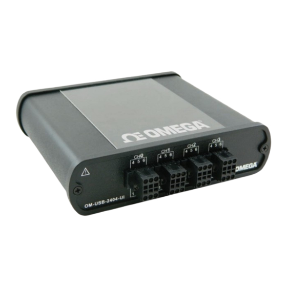
Figure 3. Rear panel Spring terminals The OM-USB-2404-UI has four 6-terminal connectors (CH0 to CH3) that provide connections for four analog input channels. The signal names for the spring terminal in each connector are listed in the table below. 6-terminal connector signal names... -
Page 11: Strain Relief Slot
— — — Refer to "OM-USB-2404-UI circuitry" on page 13 for information about connections in each mode. Strain relief slot Use the strain relief slot to keep the USB cable from disconnecting from the device inadvertently. Feed a tie wrap through the slot and secure to the USB cable when it is connected to the device. -
Page 12: Teds Sensor Connections
OM-USB-2404-UI User's Guide Functional Details TEDS sensor connections The OM-USB-2404-UI supports class II TEDS "smart" sensors only. Connect the two TEDS lines to TEDS Data (T+) and TEDS Common (T–), and ensure that neither T+ nor T– is tied in common to any of the signal inputs (terminals 3 through 6). -
Page 13: Om-Usb-2404-Ui Circuitry
Figure 7. Input circuitry for one channel Voltage and current modes In voltage and current modes, connect the signal source to the OM-USB-2404-UI across the HI and LO terminals. The current is computed from the voltage that the ADC measures across an internal shunt resistor. -
Page 14: 3-Wire Rtd Mode
OM-USB-2404-UI User's Guide Functional Details 3-wire RTD mode 3-wire RTD mode sources a current which varies based on the resistance of the load between the EX+ and EX– terminals. This mode compensates for lead wire resistance in hardware if all lead wires have the same resistance. -
Page 15: Thermocouple Mode
Each channel has a built-in thermistor for cold-junction compensation (CJC) calculations. For improved CJC sensor accuracy, operate the OM-USB-2404-UI in a stable temperature environment, and avoid placing heat sources near the device or its connectors. Open thermocouple detection is not supported. Refer to the Specifications chapter for more information about accuracy. -
Page 16: Chapter 4 Specifications
Chapter 4 Specifications All specifications are subject to change without notice. Typical for the range 0 to 60 °C unless otherwise noted. Analog input Table 1. Analog input specifications Parameter Conditions Specification Number of channels A/D converter resolution 24-bit A/D converter type Delta-Sigma with analog pre-filtering Sampling mode Simultaneous... -
Page 17: Input Mode Ranges
OM-USB-2404-UI User's Guide Specifications Input mode ranges Table 2. Input mode range specifications Input mode Nominal range(s) Actual range(s) Voltage ±60 V, ±15 V, ±4 V, ±1 V, ±125 mV ±60 V, ±15 V, ±4 V, ±1 V, ±125 mV Current ±25 mA... -
Page 18: Input Noise
OM-USB-2404-UI User's Guide Specifications 4-wire and 3-wire RTD, Pt 1000 ±15 ±6 4-wire and 3-wire RTD, Pt 100 ±15 ±60 Quarter-bridge, 350 Ω ±15 ±120 Quarter-bridge, 120 Ω ±15 ±240 Half-bridge, ±500 mV/V ±3 ±20 Full-bridge, ±62.5 mV/V ±3 ±20 Full-bridge, ±7.8 mV/V... -
Page 19: Bus Interface
10 to 90% RH, non-condensing Storage humidity 5 to 95% RH, non-condensing Maximum altitude 2000 meter (6562 feet) The OM-USB-2404-UI is intended for indoor use only, but may be used outdoors if installed in a Note 2: suitable enclosure Mechanical Table 11. Mechanical specifications... - Page 20 OM-USB-2404-UI User's Guide Specifications Table 14. Signal names Terminal number Signal name Signal description TEDS Data T– TEDS Common EX+/HI (Note 4) Positive excitation or input signal Positive input signal EX–/LO (Note 4) Negative excitation or input signal Negative input signal Note 4: Depending on the input mode, terminals 3 and 5 are either excitation signals or input signals.
- Page 21 Department will issue an Authorized Return (AR) number immediately upon phone or written request. Upon examination by OMEGA, if the unit is found to be defective, it will be repaired or replaced at no charge. OMEGA’s WARRANTY does not apply to defects resulting from any action of the purchaser, including but not limited to mishandling, improper interfacing, operation outside of design limits, improper repair, or unauthorized modification.
- Page 22 Where Do I Find Everything I Need for Process Measurement and Control? OMEGA…Of Course! Shop online at omega.com TEMPERATURE M U Thermocouple, RTD & Thermistor Probes, Connectors, Panels & Assemblies M U Wire: Thermocouple, RTD & Thermistor M U Calibrators & Ice Point References M U Recorders, Controllers &...
Need help?
Do you have a question about the OM-USB-2404-UI and is the answer not in the manual?
Questions and answers