Table of Contents
Advertisement
Quick Links
� User!s Gui � e
WARRANTY
Shop online at
[omega.com•]
-- -LEDMEGA·-
omega.com
e-mail: info@omega.com
For latest product manuals:
omegamanual.info
IS09001
IS09001
CEIITIFIB>
CEIITIRED
CORPOMlE QIJMJlY
CDRPORAJE QUAlJTY
STAMFORD, CT
MANCHESTl:R, UK
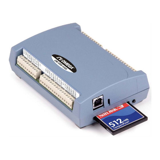
OM-USB-5203
8 Channel Temperature
Measurement
USB Data Acquisition
Module/Data Logger
Advertisement
Table of Contents

Related Manuals for Omega OM-USB-5203


Summary of Contents for Omega OM-USB-5203
- Page 1 � User!s Gui � e WARRANTY Shop online at [omega.com•] -- -LEDMEGA·- omega.com e-mail: info@omega.com For latest product manuals: omegamanual.info IS09001 IS09001 CEIITIFIB> CEIITIRED CORPOMlE QIJMJlY CDRPORAJE QUAlJTY STAMFORD, CT MANCHESTl:R, UK OM-USB-5203 8 Channel Temperature Measurement USB Data Acquisition...
- Page 2 For Other Locations Visit omega.com/worldwide The information contained in this document is believed to be correct, but OMEGA accepts no liability for any errors it contains, and reserves the right to alter specifications without notice. WARNING: These products are not designed for use in, and should not be used for, human applications.
-
Page 3: Table Of Contents
Conventions in this user's guide ......................... 5 Where to find more information ......................... 5 Chapter 1 Introducing the OM-USB-5203 ......................6 Logging data with the OM-USB-5203 ..........................6 Functional block diagram ........................... 7 Chapter 2 Installing the OM-USB-5203 ......................... 8 Unpacking................................ - Page 4 CompactFlash memory card slot ............................19 Data logging button .................................19 External power supply ............................20 Disconnecting the OM-USB-5203 from the computer ..................20 Transferring binary data after a logging session ....................20 Converting binary data after a logging session ....................20 Chapter 5 Specifications ............................
-
Page 5: Preface
Preface About this User’s Guide What you will learn from this user's guide This user's guide describes the Omega Engineering OM-USB-5203 data acquisition device and lists device specifications. Conventions in this user's guide For more information Text presented in a box signifies additional information and helpful hints related to the subject matter you are reading. -
Page 6: Introducing The Om-Usb-5203
External power is required for data logging operations Due to processing limitations, you cannot log data to the memory card when the OM-USB-5203 is connected to your computer's active USB bus. When operating as a data logger, disconnect the USB cable from the computer, and connect the external power supply shipped with the device. -
Page 7: Functional Block Diagram
You can use InstaCal to convert the files to format for use in Microsoft Excel files, or to .csv .txt format for use in other applications. Functional block diagram OM-USB-5203 functions are illustrated in the block diagram shown here. Figure 1.OM-USB-5203 functional block diagram... -
Page 8: Installing The Om-Usb-5203
Installing the hardware To connect the OM-USB-5203 to your system, turn on your computer and connect the USB cable to an available USB port on the computer or to an external USB hub connected to the computer. Connect the other end of the USB cable to the USB connector on the device. -
Page 9: Chapter 3 Sensor Connections
Screw terminal pinout The OM-USB-5203 has four rows of screw terminals – two rows on the top edge of the housing, and two rows on the bottom edge. Each row has 26 connections. Between each bank of screw terminals are two integrated CJC sensors used for thermocouple measurements. -
Page 10: Cjc Sensors
Do not connect two different sensor categories to the same channel pair The OM-USB-5203 provides a 24 bit A/D converter for each channel pair. Each channel pair can monitor one sensor category. To monitor a sensor from a different category, connect the sensor to a different channel pair (input terminals). -
Page 11: Thermocouple Connections
Sensor Connections Thermocouple connections Connect thermocouples to the OM-USB-5203 such that they are floating with respect to GND. A thermocouple consists of two dissimilar metals that are joined together at one end. When the junction of the metals is heated or cooled, a voltage is produced that correlates to temperature. -
Page 12: Two-Wire Configuration
Two-wire configuration The easiest way to connect an RTD sensor or thermistor to the OM-USB-5203 is with a two-wire configuration, since it requires the fewest connections to the sensor. With this method, the two wires that provide the RTD sensor with its excitation current also measure the voltage across the sensor. -
Page 13: Three-Wire Configuration
Figure 6. Figure 6. Three-wire RTD or thermistor sensor measurement configuration When you select a three-wire sensor configuration with InstaCal, the OM-USB-5203 measures the lead resistance on the first channel (C#H/C#L) and measures the sensor itself using the second channel (C#H/C#L). -
Page 14: Semiconductor Sensor Measurements
Use InstaCal to select the sensor type (LM35, TMP35 or equivalent) and the sensor input channel to connect the sensor. Wiring configuration Connect the semiconductor sensor to the OM-USB-5203 using a single-ended configuration, as shown in Figure 10. The OM-USB-5203device provides pins for powering the sensor. -
Page 15: Digital I/O Connections
When you configure the digital bits for input, you can use the OM-USB-5203 digital I/O terminals to detect the state of any TTL-level input. Refer to the schematic shown in Figure 11. If you set the switch to the +5 V input, DIO0 reads TRUE (1). -
Page 16: Chapter 4 Functional Details
The OM-USB-5203 has two high-resolution temperature sensors that are integrated into the design of the OM-USB-5203. One sensor is located on the right side of the package, and one sensor is located at the left side. The CJC sensors measure the average temperature at the terminal blocks so that the cold junction voltage can be calculated. -
Page 17: Rtd And Thermistor Measurements
RTDs and thermistors are resistive devices that require an excitation current to produce a voltage drop that can be measured differentially across the sensor. The OM-USB-5203 measures the sensor resistance by forcing a known excitation current through the sensor and then measuring (differentially) the voltage across the sensor to determine its resistance. -
Page 18: Screw Terminals
USB connector to the external power supply. The LED uses up to 5 mA of current. The function of the LED varies according to whether the OM-USB-5203 is connected to an active USB port, or when the device is logging data and connected to the external power supply. -
Page 19: Compactflash Memory Card Slot
The device caches log data in volatile memory prior to writing to the memory card. Pressing the data logging button has no effect when the OM-USB-5203 is connected to an active USB port and not logging data. External power required for data logging Due to processing limitations, data logging is not allowed when the OM-USB-5203 is attached to an active USB bus. -
Page 20: External Power Supply
You don't need to shut down your computer to disconnect the OM-USB-5203. Refer to the instructions below when disconnecting the OM-USB-5203 from your computer's USB port. In most cases, the OM-USB-5203 shows up as a mass storage device in Windows. To avoid losing data, safely remove the device from Windows before disconnecting it by using the... -
Page 21: Chapter 5 Specifications
Chapter 5 Specifications All specifications are subject to change without notice. Typical for 25 °C unless otherwise specified. Specifications in italic text are guaranteed by design. Analog input Table 1. Generic analog input specifications Parameter Conditions Specification A/D converters Four dual 24-bit, Sigma-Delta type Number of channels 8 differential Input isolation... -
Page 22: Compatible Sensors
OM-USB-5203 User's Guide Specifications Table 2. Channel configuration specifications Sensor Category Conditions Max number of sensors (all channels configured alike) Disabled (Note 1) Thermocouple J, K, S, R, B, E, T, or N 8 differential channels Semiconductor sensor 8 differential channels... -
Page 23: Semiconductor Sensor Measurement Accuracy
OM-USB-5203 User's Guide Specifications Table 4. Thermocouple accuracy specifications, including CJC measurement error Sensor Type Maximum error (°C) Typical error (°C) Temperature range (°C) ±1.499 ±0.507 –210 to 0 ±0.643 ±0.312 0 to 1200 ±1.761 ±0.538 –210 to 0 ±0.691 ±0.345... -
Page 24: Thermistor Measurement Accuracy
OM-USB-5203 User's Guide Specifications Thermistor measurement accuracy The error shown in Table 7 below does not include errors of the sensor itself. The sensor linearization is performed using a Steinhart-Hart linearization algorithm. These specs are for one year while operating the device between 15 °C and 35 °C. -
Page 25: Throughput Rate To Pc
OM-USB-5203 User's Guide Specifications Throughput rate to PC The analog inputs are configured to run continuously. Each channel is sampled twice per second. The maximum latency between when a sample is acquired and the temperature data is provided by the USB unit is approximately 0.5 seconds. -
Page 26: Temperature Alarms
OM-USB-5203 User's Guide Specifications Temperature alarms Table 11. Temperature alarm specifications Parameter Specification Number of alarms 8 (one per digital I/O line) Alarm functionality Each alarm controls its associated digital I/O line as an alarm output. The input to each alarm may be any of the analog temperature input channels. -
Page 27: Data Logging
OM-USB-5203 User's Guide Specifications Data Logging Table 14. Data logging specifications Parameter Specification Standalone power supply USB power adapter 2.5 watt USB adapter with interchangeable plugs (Includes plug for USA) Memory card type CompactFlash Supplied memory card 512 MB CompactFlash card... -
Page 28: Usb +5V Voltage
OM-USB-5203 User's Guide Specifications USB +5V voltage Table 16. USB +5 V voltage specifications Parameter Specification USB +5 V (VBUS) input voltage range 4.75 V min to 5.25 V max Power Table 17. Power specifications Parameter Conditions Specification Connected to USB... -
Page 29: Current Excitation Outputs (Ix+)
OM-USB-5203 User's Guide Specifications Current excitation outputs (Ix+) The device has four current excitation outputs, with I1+/I1– dedicated to the CH0/CH1 analog inputs, I2+/I2– dedicated to CH2/CH3, I3+/I3– dedicated to CH4/CH5, and I4+/I4– dedicated to CH6/CH7. The excitation output currents should always be used in this dedicated configuration. -
Page 30: Screw Terminal Connector
OM-USB-5203 User's Guide Specifications Screw terminal connector Table 22. Screw terminal connector specifications Connector type Screw terminal Wire gauge range 16 AWG to 30 AWG Table 23. Screw terminal pinout Signal Name Pin Description Signal Name Pin Description CH0/CH1 current excitation source I4–... - Page 31 Department will issue an Authorized Return (AR) number immediately upon phone or written request. Upon examination by OMEGA, if the unit is found to be defective, it will be repaired or replaced at no charge. OMEGA’s WARRANTY does not apply to defects resulting from any action of the purchaser, including but not limited to mishandling, improper interfacing, operation outside of design limits, improper repair, or unauthorized modification.
- Page 32 Where Do I Find Everything I Need for Process Measurement and Control? OMEGA…Of Course! Shop online at omega.com TEMPERATURE Thermocouple, RTD & Thermistor Probes, Connectors, Panels & Assemblies Wire: Thermocouple, RTD & Thermistor Calibrators & Ice Point References Recorders, Controllers & Process Monitors...
Need help?
Do you have a question about the OM-USB-5203 and is the answer not in the manual?
Questions and answers