Table of Contents
Advertisement
Quick Links
Advertisement
Table of Contents

Related Manuals for Tektronix A621


Summary of Contents for Tektronix A621
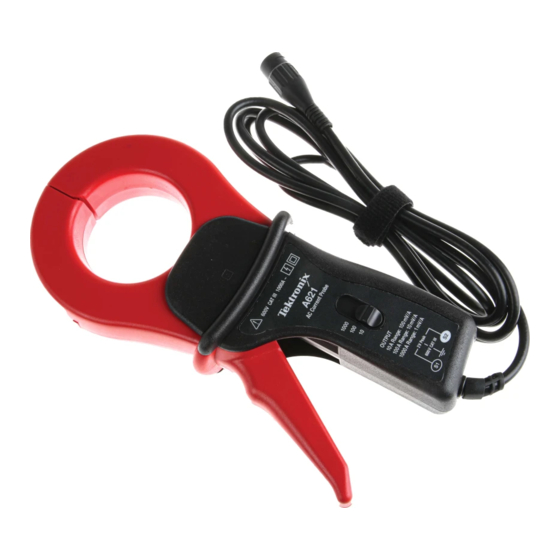
- Page 1 Instructions A621 1000 Amp AC Current Probe 070-8882-02...
- Page 2 Copyright © Tektronix, Inc. All rights reserved. Tektronix products are covered by U.S. and foreign patents, issued and pending. Information in this publication supercedes that in all previously published material. Specifications and price change privileges reserved. Tektronix, Inc., P.O. Box 500, Beaverton, OR 97077 TEKTRONIX and TEK are registered trademarks of Tektronix, Inc.
- Page 3 Tektronix, with shipping charges prepaid. Tektronix shall pay for the return of the product to Customer if the shipment is to a location within the country in which the Tektronix service center is located. Customer shall be responsible for paying all shipping charges, duties, taxes, and any other charges for products returned to any other locations.
-
Page 4: Contacting Tektronix
6:00 a.m. -- 5:00 p.m. Pacific Standard Time This phone number is toll free in North America. After office hours, please leave a voice mail message. Outside North America, contact a Tektronix sales office or distributor; see the Tektronix web site for a list of offices. www.hyxyyq.com... -
Page 5: General Safety Summary
Do Not Operate With Suspected Failures. If you suspect there is damage to this product, have it inspected by qualified service personnel. Do Not Operate in Wet/Damp Conditions. Do Not Operate in an Explosive Atmosphere. Keep Product Surfaces Clean and Dry. www.hyxyyq.com A621 Instructions... - Page 6 WARNING indicates an injury hazard not immediately accessible as you read the marking. CAUTION indicates a hazard to property including the product. Symbols on the Product. These symbols may appear on the product: Double CAUTION Insulated Refer to Manual www.hyxyyq.com A621 Instructions...
-
Page 7: Product Description
The A621 is especially useful where the display and measurement of distorted current waveforms and harmonics is required. The A621 is also compatible with DMMs by using the BNC-to-banana plug adapter (recommended accessory, see page 17 for more information). -
Page 8: Operating Basics
“hot” and neutral wires may give you a zero reading. To load From source Figure 1: Connecting the A621 (Remember to unclamp the probe from the conductor before disconnecting it from your meter or instrument.) A621 Instructions... - Page 9 While the RMS current may be low, the momentary peaks may be quite high. Figure 2 shows the difference between the line current drawn by a resistive load and a motor controller. Resistive Load Motor Controller Figure 2: Typical Current Waveforms A621 Instructions www.hyxyyq.com...
- Page 10 Operating Basics If you are using the A621 with a multimeter, use the BNC-to-banana adapter (recommended accessory) to connect the probe. Connect the black lead to the meter COM, and the red lead to the VΩ input. Set the meter to the AC Volts position.
-
Page 11: Specifications
Specifications These characteristics apply to an A621 probe installed on a Tektronix TDS320 oscilloscope. The oscilloscope must be warmed up for at least 20 minutes and be in an environment within the limits in Table 3. Table 1: Electrical Characteristics... -
Page 12: Typical Response Curves
@ 50 A --5.00 1000 10,000 100,000 Frequency (Hz) Phase Shift vs. Frequency 1 mV/A Range 5.00 0.00 --5.00 --10.00 --15.00 --20.00 --25.00 --30.00 @ 10 A @ 50 A --35.00 --40.00 1000 10,000 100,000 Frequency (Hz) A621 Instructions www.hyxyyq.com... - Page 13 --20.00 @ 1A --25.00 @ 5A --30.00 1000 10,000 100,000 Frequency (Hz) Phase Shift vs. Frequency 10 mV/A Range 10.00 0.00 --10.00 --20.00 --30.00 --40.00 --50.00 @ 1A --60.00 @ 5A --70.00 1000 10,000 100,000 Frequency (Hz) A621 Instructions www.hyxyyq.com...
- Page 14 --35.00 @ 0.5A --40.00 --45.00 1000 10,000 100,000 Frequency (Hz) Phase Shift vs. Frequency 100 mV/A Range 50.00 40.00 30.00 20.00 10.00 0.00 --10.00 --20.00 @ 0.1A --30.00 @ 0.5A --40.00 --50.00 1000 10,000 100,000 Frequency (Hz) A621 Instructions www.hyxyyq.com...
- Page 15 206 mm x 48 mm x 105 mm Dimensions (8.11 x 1.89 x 4.13 inches) Maximum Conductor Size 54 mm (2.13 inches) Cable Length 1.5 m (5 feet) Weight 650 g (1.43 lb) Figure 4: Physical dimensions A621 Instructions www.hyxyyq.com...
- Page 16 Equipment at this level is typically in a fixed industriallocation. CAT II Local-level mains (wall sockets). Equipment at this level includes appliances, portable tools, and similar products. Equipment is usually cord-connected. CAT I Secondary (signal level) or battery operated circuits of electronic equipment. A621 Instructions www.hyxyyq.com...
- Page 17 Do not operate in environments where conductive pollutants may be present. U.S. Nationally UL3111-1, First Edition & UL3111-2-032, First Edition Recognized Testing CSA C22.2 No. 1010.1-92 & CAN/CSA C22.2 No. 1010.2.031-94 Laboratory Listing IEC61010-1/A2 EN 61010-2-032 Pollution Degree 2 A621 Instructions www.hyxyyq.com...
-
Page 18: Performance Verification
Performance Verification This procedure verifies that the A621 performs as specified. It can also be an acceptance check. There are no A621 adjustments. This procedure is valid when: • The system is operated in an environment that conforms to the A621 environmental specifications (0。... - Page 19 012-0031-00 012-0039-00 Requires Tektronix TM 500 Series or Tektronix TM 5000 Series Power Module 100 Turn Current Loop CAUTION. It is not recommended that a coil with greater than 100 turns be made. Magnetic fields are produced that may cause a malfunction in heart pacemakers, or damage to sensitive equipment.
- Page 20 • vertical deflection to 500 mV / div. • coupling to DC 4. Set the A621 sensitivity switch to 100 mV / A and center the trace on the oscilloscope screen. 5. Clamp the A621 around the 100 turn current loop.
- Page 21 V/div setting reading play 100 mV/A 200 mV/div. 50 ±1 mA 1.4 ±0.1 V P--P 10 mV/A 20 mV/div. 50 ±1 mA 140 ±10 mV P--P 1 mV/A 2 mV/div. 50 ±1 mA 14 ±1 mV P--P A621 Instructions www.hyxyyq.com...
-
Page 22: Maintenance
The box should have a carton test strength of at least 200 pounds. 2. Put the probe into a plastic bag or wrap to protect it from dampness. 3. Place the probe into the box and stabilize it with light packing material. 4. Seal the carton with shipping tape. A621 Instructions www.hyxyyq.com... -
Page 23: Replaceable Parts
• a BNC-to-banana plug adapter (for use with DMM’s) Tektronix part number 012-1450-00 The A621 does not have any user replaceable parts. If you should have trouble with your probe, contact your local Tektronix Service Center or representative for help.
Need help?
Do you have a question about the A621 and is the answer not in the manual?
Questions and answers