Sungrow SG110CX User Manual
Pv grid-connected inverter
Hide thumbs
Also See for SG110CX:
- User manual (131 pages) ,
- Quick installation manual (12 pages) ,
- Quick manual (21 pages)

Related Manuals for Sungrow SG110CX


Summary of Contents for Sungrow SG110CX
- Page 1 PV Grid-Connected Inverter User Manual SG110CX SG110CXPV Grid-Connected InverterUser ManualSG110CX-UEN-Ver20-202111 SG110CX-UEN-Ver20-202111...
-
Page 3: All Rights Reserved
Software Licenses • It is prohibited to use data contained in firmware or software developed by SUNGROW, in part or in full, for commercial purposes by any means. • It is prohibited to perform reverse engineering, cracking, or any other operations that... -
Page 4: About This Manual
Validity This manual is valid for the following inverter models: • SG110CX They will be referred to as "inverter" hereinafter unless otherwise specified. Target Group This manual is intended for inverter owners who will have the ability to interact with the inver- ter and qualified personnel who are responsible for the installation and commissioning of the inverter. - Page 5 Indicates a hazard with a low level of risk that, if not avoided, could result in minor or moderate injury. Indicates a situation that, if not avoided, could result in equipment or property damage. Indicates additional information, emphasized contents or tips that may be helpful, e.g.
-
Page 7: Table Of Contents
Contents All Rights Reserved .....................I About This Manual......................II 1 Safety .........................1 1.1 PV Panels......................1 1.2 Utility Grid ......................1 1.3 Inverter ......................2 2 Product Description ..................4 2.1 System Introduction ..................4 2.2 Product Introduction..................5 2.3 Symbols on the Product ..................7 2.4 LED Indicator ....................7 2.5 DC Switch......................8 2.6 Circuit Diagram ....................8 2.7 Function Description ..................9... - Page 8 4.6 Installing the Inverter..................21 5 Electrical Connection ..................23 5.1 Safety Instructions ..................23 5.2 Terminal Description ..................23 5.3 Electrical Connection Overview ..............25 5.4 Crimp OT/DT terminal ...................27 5.5 External Grounding Connection ..............28 5.5.1 External Grounding Requirements............28 5.5.2 Connection Procedure.................29 5.6 Opening the Wiring Compartment ..............29 5.7 AC Cable Connection ...................30 5.7.1 AC Side Requirements ................30 5.7.2 Requirements for OT/DT Terminal ............32...
- Page 9 6.2 Commissioning Procedure ................56 7 iSolarCloud App ....................57 7.1 Brief Introduction ..................57 7.2 Installing the App ..................57 7.3 Function Overview..................58 7.4 Login ......................58 7.4.1 Requirements ..................58 7.4.2 Login Procedure .................58 7.5 Home page ....................62 7.6 Run Information....................65 7.7 Records .......................66 7.8 More......................68 7.8.1 System Parameters................68 7.8.2 Operation Parameters .................69...
-
Page 11: Safety
The safety instructions in this manual cannot cover all the precautions that should be followed. Perform operations considering actual onsite conditions. • SUNGROW shall not be held liable for any damage caused by violation of the safety instructions in this manual. •... -
Page 12: Inverter
1 Safety User Manual All electrical connections must be in accordance with local and national standards. Only with the permission of the local utility grid company, the inverter can be con- nected to the utility grid. Inverter Danger to life from electric shocks due to live voltage Do not open the enclosure at any time. - Page 13 User Manual 1 Safety Only qualified personnel can perform the country setting. Unauthorized alteration may cause a breach of the type-certificate marking. Risk of inverter damage due to electrostatic discharge (ESD)! By touching the electronic components, you may damage the inverter. For inverter handling, be sure to: •...
-
Page 14: Product Description
Description Item Note Monocrystalline silicon, polycrystalline silicon and thin-film PV strings without grounding. Inverter SG110CX Grid connection Includes devices such as AC circuit breaker, SPD, metering cabinet device. Boost the low voltage from the inverter to grid-compatible me- Transformer dium voltage. -
Page 15: Product Introduction
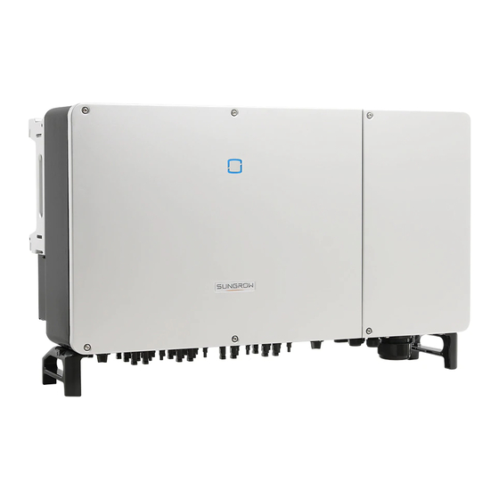
User Manual 2 Product Description Product Introduction Model Description The model description is as follows : Appearance The following figure shows the dimensions of the inverter. The image shown here is for refer- ence only. The actual product received may differ. - Page 16 2 Product Description User Manual figure 2-2 Inverter Appearance * The image shown here is for reference only. The actual product received may differ. Description Name LED indicator HMI interface to indicate the present working state of the panel inverter. Warning symbols, nameplate, and QR code.
-
Page 17: Symbols On The Product
User Manual 2 Product Description figure 2-3 Dimensions of the Inverter(in mm) Symbols on the Product Symbol Explanation Do not dispose of the inverter together with household waste. TÜV mark of conformity. CE mark of conformity. Regulatory compliance mark. CGC-SOLAR mark of conformity. Danger to life due to high voltages! Only qualified personnel can open and service the inverter. -
Page 18: Dc Switch
DC Switch The DC switch is used to disconnect the DC current safely whenever necessary. The SG110CX is equipped with three DC switches, and each DC switch controls its corre- sponding DC terminals. Turn the DC switches to the ON position before restarting the inverter. -
Page 19: Function Description
User Manual 2 Product Description figure 2-4 Circuit Diagram • The MPPT is utilized for DC input to ensure the maximum power from the PV array at dif- ferent PV input conditions. • The inverter circuit converts the DC power into AC power and generates AC power to loads or utility grid through the AC terminal. - Page 20 2 Product Description User Manual • For negative voltage scheme, after the PID is enabled, the voltage to ground of all PV strings is lower than 0, and therefore the PV string-to-ground voltage is a negative value. • Before enabling the PID recovery function, make sure the voltage polarity of the PV modules to ground meets requirement.
-
Page 21: Unpacking And Storage
• Check the inner contents for damage after unpacking. Contact SUNGROW or the transport company in case of any damage or incompleteness, and provide photos to facilitate services. Do not dispose of the original packing case. It is recommended to store the device in the original packing case when the device is decommissioned. -
Page 22: Mechanical Mounting
Mechanical Mounting Respect all local standards and requirements during mechanical installation. Safety during Mounting Make sure there is no electrical connection before installation. In order to avoid electric shock or other injury, make sure that holes will not be drilled over any electricity or plumbing installations. Risk of injury due to improper handling •... -
Page 23: Environment Requirements
User Manual 4 Mechanical Mounting 4.2.1 Environment Requirements • The installation environment must be free of inflammable or explosive materials. • The location should be not accessible to children. • The ambient temperature and relative humidity must meet the following requirements. •... -
Page 24: Clearance Requirements
4 Mechanical Mounting User Manual In case the installation site is a level surface, mount the inverter to the horizontal- mounting bracket to meet the mounting angle requirements, as shown in the figure below. Take the following items into account when designing the bracket scheme: •... -
Page 25: Installation Tools
User Manual 4 Mechanical Mounting * In case the distance is less than 800 mm, move the inverter from the mounting-bracket or wall before maintaining fans. In case of multiple inverters, reserve specific clearance between the inverters. For other in- stallation scenarios, please refer to the relevant technical documents on http://support.sun- growpower.com/. - Page 26 4 Mechanical Mounting User Manual table 4-1 Tool specification Goggles Earplugs Dust mask Protective gloves Insulated shoes Utility knife Slotted screwdriver Phillips screwdriver (M4, M6, M8) (M2, M6) Hammer drill Pliers Marker Level (φ12, φ14) Rubber mallet Socket wrench set Wrench Wrist strap (13 mm, 16 mm)
-
Page 27: Moving The Inverter
User Manual 4 Mechanical Mounting MC4 terminal MC4 terminal Multimeter RJ45 crimping tool crimping pliers wrench ≥ 1100 Vdc 4–6mm Vacuum cleaner Moving the Inverter Before installation, remove the inverter from the packing case and move it to the installation site. -
Page 28: Hoisting Transport
4 Mechanical Mounting User Manual The ground surface on which the inverter is to be placed should be covered with a sponge pad, foam cushion or the like to prevent the inverter bottom from scratches. - - End 4.4.2 Hoisting Transport step 1 Release the sealing screws on the mounting ears and store them properly. -
Page 29: Installing The Mounting-Bracket
User Manual 4 Mechanical Mounting Keep the inverter balanced throughout the hoisting process and avoid collisions with walls or other objects. Stop hoisting in the event of severe weather, such as heavy rain, thick fog, or strong wind. The lifting rings and the sling are not within the delivery scope. - - End Installing the mounting-bracket Inverter is installed on the wall and bracket by means of mounting bracket. -
Page 30: Wall-Mounted Installation
4 Mechanical Mounting User Manual step 3 Secure the mounting-bracket with bolts. Components Description Mounting-bracket – Full threaded bolt M10*45 – Metal bracket – Flat washer Spring washer – Hex nuts - - End 4.5.2 Wall-Mounted Installation step 1 Assemble the mounting-bracket by using the connecting bar. step 2 Level the assembled mounting-bracket by using the level, and mark the positions for drilling holes on the installation site. -
Page 31: Installing The Inverter
User Manual 4 Mechanical Mounting step 4 Fix the mounting-bracket with the expansion bolts. Components Description – Wall Fastening the bolt in the sequence of nut, spring wash- Expansion bolt er, slat washer Mounting-bracket – - - End Installing the Inverter step 1 Take out the inverter from the packing case. - Page 32 4 Mechanical Mounting User Manual - - End...
-
Page 33: Electrical Connection
Electrical Connection Safety Instructions Prior to any electrical connections, keep in mind that the inverter has dual power supplies. It is mandatory for the qualified personnel to wear personal protective equipments (PPE) dur- ing the electrical work. Danger to life due to a high voltage inside the inverter! •... - Page 34 5 Electrical Connection User Manual figure 5-1 Terminal Description(For a multi-core cable) figure 5-2 Terminal Description(For four single-core cables) * The image shown here is for reference only. The actual product received may differ.
-
Page 35: Electrical Connection Overview
User Manual 5 Electrical Connection Item Terminal Mark Note PV terminals + / - MC4 PV connector RS485 communication, digital input/output DI/ Communica- COM1 / 2 / 3 tion terminal COM4 For communication module connection. AC wiring Used for AC output cable connection. terminal Standby Used for internal grounding. - Page 36 (2) In the case of four single-core cables, a spare AC sealing plate accessory is required as shown in the following figure. To purchase the AC sealing plate accessory, contact SUNGROW. figure 5-3 Spare AC Sealing Plate Inverter for Australia and New Zealand are equipped with the four-core sealing...
-
Page 37: Crimp Ot/Dt Terminal
User Manual 5 Electrical Connection table 5-2 PE Wire Requirements PE Wire PE Wire Cross Cross Note Section S Section The specifications are valid only when the phase wire and PE wire use the same material. If otherwise, ensure S / 2 S >... -
Page 38: External Grounding Connection
The ground connection of this external grounding terminal cannot replace the connection of the PE terminal of the AC cable. Make sure those terminals are both grounded reliably. Otherwise, SUNGROW shall not be held liable for any damage caused by the violation. -
Page 39: Connection Procedure
User Manual 5 Electrical Connection 5.5.2 Connection Procedure step 1 Prepare the cable and OT/DT terminal, refer to " Crimp OT/DT terminal". step 2 Remove the screw on the grounding terminal and fasten the cable with a screwdriver. step 3 Apply paint to the grounding terminal to ensure corrosion resistance. The grounding screws have been anchored to the side of the inverter before deliv- ery, and do not need to be prepared. -
Page 40: Ac Cable Connection
An independent circuit breaker or fuse is installed on the output side of the inverter to ensure safe disconnection from the grid. Recommended rated voltage Inverter Model Recommended rated current SG110CX 400V 200A Never connect a load between the inverter and the circuit breaker. Multiple inverters cannot share one circuit breaker. - Page 41 The apparent power of the inverter should never exceed the power of the transformer. The maximum AC current of all inverters connected in parallel must be taken into ac- count. If more than 25 inverters are connected to the grid, contact SUNGROW. •...
-
Page 42: Requirements For Ot/Dt Terminal
5 Electrical Connection User Manual • Take ambient temperature, relative humidity, altitude, air quality, and other environmental conditions into account when selecting and installing the transformer. 5.7.2 Requirements for OT/DT Terminal OT/DT terminals (not included in the delivery scope) are required for fixing AC cables to the terminal block. - Page 43 User Manual 5 Electrical Connection step 5 Strip the protection layer and insulation layer by specific length, as described in the figure below. step 6 Make the cable and crimp OT/DT terminal. step 7 Secure the wires to corresponding terminals. Note the terminal positions of PE wire and N wire.
- Page 44 5 Electrical Connection User Manual Ensure that the depth L of the socket used is not less than 28mm. step 8 Gently pull the cable backwards to ensure firm connection, and fasten the swivel nut clockwise. If the PE cable is an independent single-core cable, it should be inserted into the cabinet through the standby grounding terminal.
-
Page 45: Connection Procedure(L1/L2/L3/N, For Four Single-Core Cables)
User Manual 5 Electrical Connection - - End 5.7.4 Connection Procedure(L1/L2/L3/N, For four single-core cables) step 1 Open the wiring compartment. For details, refer to"5.6 Opening the Wiring Compartment". step 2 Disconnect the AC-side circuit breaker and prevent it from inadvertent reconnection. step 3 Loosen the swivel nut of the AC waterproof connector and select a seal according to the ca- ble outer diameter, remove the inner sealing ring if the cable diameter is larger than 22 mm. - Page 46 5 Electrical Connection User Manual step 5 Strip the protection layer and insulation layer by specific length, as described in the figure below. step 6 Make the cable and crimp OT/DT terminal. step 7 Secure the wires to corresponding terminals. Note the terminal positions of PE wire and N wire.
-
Page 47: Connection Procedure(L1/L2/L3/Pe, For Four Single-Core Cables)
User Manual 5 Electrical Connection step 9 Install the protection cover - - End 5.7.5 Connection Procedure(L1/L2/L3/PE, For four single-core cables) step 1 Open the wiring compartment. For details, refer to"5.6 Opening the Wiring Compartment". step 2 Disconnect the AC-side circuit breaker and prevent it from inadvertent reconnection. step 3 Loosen the swivel nut of the AC waterproof connector and select a seal according to the ca- ble outer diameter, remove the inner sealing ring if the cable diameter is larger than 22 mm . - Page 48 5 Electrical Connection User Manual step 4 Remove the protection cover and store the released screws properly. step 5 Strip the protection layer and insulation layer by specific length, as described in the figure below. step 6 Make the cable and crimp OT/DT terminal. step 7 Secure the wires to corresponding terminals.
- Page 49 User Manual 5 Electrical Connection Ensure that the depth L of the socket used is not less than 28mm. step 8 Gently pull the cable backwards to ensure firm connection, and fasten the swivel nut clockwise. step 9 Install the protection cover - - End...
-
Page 50: Dc Cable Connection
5 Electrical Connection User Manual DC Cable Connection Danger of electric shock! The PV array will generate lethal high voltage once exposed to sunlight. Make sure the PV array is well insulated to ground before connecting it to the inverter. During the installation and operation of the inverter, please ensure that the positive or negative polarities of PV strings do not short-circuit to the ground. -
Page 51: Assembling The Pv Connectors
Use MC4-Evo2 DC terminals if the maximum input voltage is greater than 1,000 V. To purchase the MC4-Evo2 DC terminals, contact SUNGROW. • Select appropriate DC terminals as required above. Otherwise, SUNGROW shall be held no liability for the damage caused. - Page 52 5 Electrical Connection User Manual SUNGROW provides corresponding PV connectors in the scope of delivery for quick connection of PV inputs. To ensure IP66 protection, use only the supplied connector or the connector with the same ingress of protection. step 1 Strip 7 mm–8 mm of the insulation from each PV cable.
-
Page 53: Installing The Pv Connector
• Arc or contactor over-temperature may occur if the PV connectors are not firmly connected in place, and SUNGROW shall not be held liable for any damage caused due to this operation. step 4 Follow the foregoing steps to connect PV connectors of other PV strings. -
Page 54: Rs485 Connection
5 Electrical Connection User Manual If the DC input is connected inversely and the DC switch has been rotated to "ON", do not operate immediately. Otherwise, the equipment may be damaged. Please turn the DC switch to "OFF" and remove the DC connector to adjust the polarity of the strings when the string current is lower than 0.5A. -
Page 55: Rs485 Communication System
User Manual 5 Electrical Connection table 5-4 RS485_1 port terminal definition (RJ45) Definition PIN1~2 RS485 B, RS485B differential signal- PIN3 PIN4~5 RS485 A, RS485A differential signal+ PIN6 PIN7~8 The terminal block interface and RJ45 interface have the same function with different wiring manner. - Page 56 5 Electrical Connection User Manual figure 5-5 Multi-inverter Communication System【RS485_1 Interface(Terminal Block)】 figure 5-6 Multi-inverter Communication System【RS485_1 Interface(RJ45)】 When more than 15 inverters are connected to the same daisy chain, in order to ensure the communication quality, the Logger at the first end of the daisy chain needs to be equipped with a terminal resistor of 120Ω, the inverter at the last end needs to be equipped with a RS485-dip switch (SW1), and the shielding layer of the communication cable should be sin- gle-point grounded.
-
Page 57: Connection Procedure(Terminal Block)
User Manual 5 Electrical Connection figure 5-7 Configuration of Dip Switch (N≥15) The length of the RS485 cable and twisted pair cable should be no longer than 1,200m. If multiple inverters are connected to the data collector Logger3000, the number of permissible daisy chains and the number of devices allowed to be connected should meet the requirements (refer to the user manual for the Logger3000). -
Page 58: Connection Procedure (Rj45 Ethernet Port)
5 Electrical Connection User Manual Outer Diameter D(mm) Seal 4.5 ~ 6 6 ~ 12 a + b 12 ~ 18 step 3 Secure the cable to the terminal base. step 4 Insert the terminal base into the corresponding terminal. step 5 Pull the cable gently to make sure it is secured, tighten the swivel nut clockwise. - Page 59 User Manual 5 Electrical Connection Outer Diameter D(mm) Seal 4.5 ~ 6 6 ~ 12 a + b 12 ~ 18 step 2 Strip the insulation layer of the Ethernet cable with a wire stripper, and insert the signal wires to the RJ45 connector(Pin 3 and Pin 6 are for communication connection).
-
Page 60: Dry Contact Connection
5 Electrical Connection User Manual - - End 5.10 Dry Contact Connection Dry contact cables require a cross section of 1 mm to 1.5 mm The connection procedure of the dry contact is the same as that of the RS485 ter- minal block. - Page 61 User Manual 5 Electrical Connection figure 5-8 Normal open contact figure 5-9 Normal close contact Devices connected to the relay should comply with related requirements: AC-Side Requirements DC-Side Requirements Max. voltage: 125Vac Max. voltage: 30Vdc Max. current: 5A Max. current: 5A DI terminal (emergency stop dry contact): the dry contact can be configured to be an emergency stop contact.
-
Page 62: Wiring Procedure
5 Electrical Connection User Manual figure 5-10 Local stop contact figure 5-11 Daisy chain topology When wiring DI dry contacts, ensure that the maximum wiring distance meet the require- ments in "10.2 Wring Distance of DI Dry Contact". 5.10.2 Wiring Procedure Refer to the wiring of terminal block described in chapter"5.9.3 Connection Procedure(Termi- nal Block)"... -
Page 63: Connection Procedure
Asserted when the impedance between pins 5 and 6 is detected to be above 20 kΩ Enable the DRM function through the iSolarCloud App. If there are any problems, contact SUNGROW. The DRM function is only applicable to devices for Australia and New Zealand. 5.11.2 Connection Procedure step 1 Strip the insulation layer of the Ethernet cable with a wire stripper, and insert the signal wires to the RJ45 connector. -
Page 64: Closing The Wiring Compartment
- - End 5.13 Communication Module Connection (optional) Connect the communication module produced by SUNGROW to the communication acces- sory port. After successful connection, information such as power generation and running state of the inverter can be viewed via the APP on the phone. - Page 65 User Manual 5 Electrical Connection *The image shown here is for reference only. The actual product you receive may differ. Once the communication module is in use, do not connect the inverter to a 3rd party data logger at the same time via RS485. For details on module installation and configuration, refer to the manual delivered together with the module.
-
Page 66: Commissioning
Commissioning Inspection before Commissioning Check the following items before starting the inverter: • All equipment has been reliably installed. • DC switch(es) and AC circuit breaker are in the "OFF" position. • The ground cable is properly and reliably connected. •... -
Page 67: Isolarcloud App
iSolarCloud App Brief Introduction The iSolarCloud App can establish communication connection to the inverter via the Blue- tooth, thereby achieving near-end maintenance on the inverter. Users can use the App to view basic information, alarms, and events, set parameters, or download logs, etc. *In case the communication module Eye, WiFi or WiNet-S is available, the iSolarCloud App can also establish communication connection to the inverter via the mobile data or WiFi, thereby achieving remote maintenance on the inverter. -
Page 68: Function Overview
7 iSolarCloud App User Manual Function Overview The App provides parameter viewing and setting functions, as shown in the following figure. figure 7-1 App function tree map Login 7.4.1 Requirements The following requirements should be met: • The AC or DC side of the inverter is powered-on. •... - Page 69 To set inverter parameters related to grid protection and grid support, contact SUNGROW to obtain the advanced account and corresponding password. step 4 If the inverter is not initialized, you will enter the quick setting screen of initializing protection...
- Page 70 7 iSolarCloud App User Manual figure 7-4 Initialization Protection Parameter Reset the protection parameters if the country setting is incorrect. Otherwise, a fault may occur. In the European region, such as Sweden, Ireland, Hungary, Portugal, Romania, Greece, Ukraine etc. whose grid code complies with EN50549, select the parame- ter EN50549_1 (LV grid- connection) or EN50549_2 (MV grid-connection) with proper manual settings.
- Page 71 User Manual 7 iSolarCloud App figure 7-5 Initialization Power Company The image shown here is for reference only. Refer to the actual interface for the supported network service providers. table 7-1 Power Company Information Network Service Provider Grid Type AS/NZS 4777.2:2015 AS/NZS 4777.2:2020 Australia A AS/NZS 4777.2:2020 Australia B AS/NZS 4777.2:2020 Australia C...
-
Page 72: Home Page
7 iSolarCloud App User Manual SA Power Networks • TS129-2019: < 10 kW for single-phase & 30 kW for three-phase • TS130-2017: > 30 kW & ≤ 200 kW • TS131-2018: > 200 kW Horizon Power • HPC-9DJ-13-0001-2019: ≤ 10 kVA for single-phase &... - Page 73 User Manual 7 iSolarCloud App figure 7-6 Home Page table 7-2 Home Page Description Designation Description System date and time of the inverter. Date and time Present operation state of the inverter. For details, refer to Inverter state "table 7-3 Description of Inverter State".
- Page 74 7 iSolarCloud App User Manual table 7-3 Description of Inverter State Description State After being energized, the inverter tracks the PV arrays’ maximum power point (MPP) and converts the DC power into AC power. This is the nor- mal operation mode. Stop The inverter is stopped.
-
Page 75: Run Information
User Manual 7 iSolarCloud App Run Information Tap Run Information on the navigation bar to enter the screen showing running information, slide the screen upwards to view all detailed information. table 7-5 Run Information Classifica- Description Parameter tion String n Voltage The input voltage of the n string Information... -
Page 76: Records
7 iSolarCloud App User Manual Classifica- Description Parameter tion B-C Line Voltage C-A Line Voltage Phase A Current Phase B Current Phase Current Phase C Current Records Tap Records on the navigation bar to enter the screen showing event records, as shown in the following figure. - Page 77 User Manual 7 iSolarCloud App figure 7-9 Detailed Fault Alarm Information Yield Record Tap Yield Record to enter the screen showing daily power generation , as shown in the fol- lowing figure. figure 7-10 Power Curve The App displays power generation records in a variety of forms, including daily power gen- eration graph, monthly power generation histogram, annual power generation histogram and total power generation histogram.
-
Page 78: More
7 iSolarCloud App User Manual Description Parameter Monthly energy Shows the power output every month in a year. histogram Annual energy Shows the power output every year. histogram Tap the time bar on the top of the screen to select a time segment and view the correspond- ing power curve. -
Page 79: Operation Parameters
User Manual 7 iSolarCloud App figure 7-12 System Parameters Boot/Shutdown Tap Boot/Shutdown to send the boot/shutdown instruction to the inverter. For Australia and New Zealand, when the DRM state is DRM0, the "Boot" option will be prohibited. Date Setting/Time Setting The correct system time is very important. - Page 80 7 iSolarCloud App User Manual figure 7-14 PID Setting table 7-7 PID Parameter Description Description Parameter Set enabling/disabling of the PID night recovery function. PID night PID Recovery recovery function operates between 22:00 pm and 5:00 am by default. If ISO impedance abnormality or PID function exception is de- tected during running of the PID function, the inverter reports a Clear PID alarm PID false alarm and reminds the user to take corresponding meas-...
-
Page 81: Power Regulation Parameters
User Manual 7 iSolarCloud App figure 7-16 NS Protection(Passive Valid) 7.8.3 Power Regulation Parameters Active Power Regulation Tap Settings→Power Regulation Parameters→Active Power Regulation to enter the screen, as shown in the following figure. figure 7-17 Active Power Regulation table 7-8 Active Power Regulation Definition/Setting Range Parameter... - Page 82 7 iSolarCloud App User Manual Definition/Setting Range Parameter Description Active power rising The rise rate of inverter active 3%/min~6000%/min gradient power per minute. Active power setting Switch for enabling/disabling Enable/Disable persistence the function of saving output limited power. Active power limit The switch for limiting output Enable/Disable power.
- Page 83 User Manual 7 iSolarCloud App figure 7-18 Reactive Power Regulation table 7-9 Reactive Power Regulation Definition/Setting Range Parameter Description Reactive power genera- Switch for enabling/disabling Enable/Disable tion at night Q at night function. Reactive power ratio at Reactive power ratio set for -100%~0%/ night the Q at night function.
- Page 84 7 iSolarCloud App User Manual Definition/Setting Range Parameter Description QP_P3 Output power at P3 on the Q 20.0%~100.0% (P) mode curve (in percentage) QP_K1 Power factor at P1 on the Q(P) Curve A/Curve mode curve C:0.800~1.000 Curve B: [-0.600~0.600]*Ac- tive Overload Rate/1000 QP_K2 Power factor at P2 on the Q(P) Curve A/Curve C:...
- Page 85 User Manual 7 iSolarCloud App Definition/Setting Range Parameter Description QU_V2 Pre-set grid voltage U2 that is 80.0%~100.0% reactive according to the grid voltage. QU_Q2 Pre-set proportion of reactive [-60.0%-60.0%]* Overload power according to the grid Rate/1000 voltage U2. QU_V3 Pre-set grid voltage U3 that is 100.0%~120.0% reactive according to the grid voltage.
-
Page 86: Communication Parameters
7 iSolarCloud App User Manual figure 7-19 Q(U) Curve figure 7-20 Q(P) Curve 7.8.4 Communication Parameters Tap Settings→Communication Parameters→Serial Port Parameters to enter the corre- sponding interface, as shown in the following figure. figure 7-21 Serial Port Parameters table 7-10 Serial Port Parameters Range Parameter Device Address... -
Page 87: Firmware Update
User Manual 7 iSolarCloud App figure 7-22 MPLC Parameters table 7-11 MPLC Parameters Range Parameter Band Num Band1, Band2 Array ID 1–255 Winding ID 1–10 7.8.5 Firmware Update To avoid download failure due to poor on-site network signal, it is recommended to download the firmware package to the mobile device in advance. -
Page 88: Password Changing
7 iSolarCloud App User Manual step 8 Tap the upgrade package file, a prompt box will pop up asking you to upgrade the firmware with the file, tap CONFIRM to perform the firmware upgrade. step 9 Wait for the file to be uploaded. When the upgrade is finished, the interface will inform you of the upgrade completion. - Page 89 User Manual 7 iSolarCloud App figure 7-23 Change Password The password shall consisit of 8–20 digits, including letters and numbers.
-
Page 90: System Decommissioning
System Decommissioning Disconnecting the Inverter For maintenance or other service work, the inverter must be switched off. Proceed as follows to disconnect the inverter from the AC and DC power sources. Lethal voltages or damage to the inverter will follow if otherwise. step 1 Disconnect the external AC circuit breaker and secure it against reconnection. -
Page 91: Disposal Of The Inverter
User Manual 8 System Decommissioning step 4 If the inverter will be used again in the future, please refer to "3.2 Inverter Storage" for a proper conservation. - - End Disposal of the Inverter Users take the responsibility for the disposal of the inverter. Some parts and devices of the inverter, such as the capacitors, may cause environ- mental pollution. -
Page 92: Troubleshooting And Maintenance
Troubleshooting and Maintenance Troubleshooting Once the inverter fails, the fault information can be displayed on the App interface. If the in- verter is equipped with an LCD screen, the fault information can be viewed on it. The fault codes and troubleshooting methods of all PV inverters are detailed in the table be- low. - Page 93 App or the LCD. Modify the overvoltage protection values with the consent of the local electric power operator. 3. Contact Sungrow Customer Service if the preceding causes are ruled out and the fault persists. Generally, the inverter will be reconnected to the grid after the grid returns to normal.
- Page 94 Grid Underfrequency 2. Check whether the protection parameters are appropriately set via the App or the LCD. 3. Contact Sungrow Customer Service if the preceding causes are ruled out and the fault persists. Generally, the inverter will be reconnected to the grid after the grid returns to normal.
- Page 95 1. Measure the actual grid, and contact the lo- cal electric power company for solutions if the Grid Abnormal grid parameter exceeds the set range. 2. Contact Sungrow Customer Service if the preceding causes are ruled out and the fault persists. Generally, the inverter will be reconnected to the grid after the grid returns to normal.
- Page 96 If so, disconnect the DC switch and adjust the polarity when the string current drops below 0.5 A. 2. Contact Sungrow Customer Service if the 532-547, PV Reverse Connection preceding causes are ruled out and the alarm...
- Page 97 Resistance layer. 3. If the cable is normal and the fault occurs on rainy days, check it again when the weath- er turns fine. 4. Contact Sungrow Customer Service if the preceding causes are ruled out and the fault persists.
- Page 98 2. Check whether the insulation between the Grounding Cable Fault ground cable and the live wire is normal. 3. Contact Sungrow Customer Service if the preceding causes are ruled out and the fault persists. 1. Disconnect the DC power supply, and...
- Page 99 2. Reconnect the communication cable of the Inverter Parallel Com- meter. munication Alarm 3. Contact Sungrow Customer Service if the preceding causes are ruled out and the alarm persists. 7, 11, 16, 19–25, 30– 34, 36, 38, 40–42, 44–...
- Page 100 432–434, abnormalities, and take corresponding correc- 500–513, tive measures when necessary. 515–518, If the fault persists, please contact Sungrow 900, 901, Power Customer Service. 910, 911 1. Check whether the corresponding string is of reverse polarity. If so, disconnect the DC switch and adjust the polarity when the string current drops below 0.5 A.
-
Page 101: Maintenance
364-395 voltage Fault later to restart the inverter. If the fault still ex- ists, contact Sungrow Customer Service. 1. Check whether the number of PV modules of the corresponding string is less than other strings. If so, disconnect the DC switch and adjust the PV module configuration when the string current drops below 0.5 A. -
Page 102: Routine Maintenance
As the inverter contains no component parts that can be maintained, never arbitra- rily replace any internal components. For any maintenance need, please contact SUNGROW. Otherwise, SUNGROW shall not be held liable for any damage caused. Servicing of the device in accordance with the manual should never be undertak- en in the absence of proper tools, test equipments or the latest revision of the manual which has been clearly and thoroughly understood. -
Page 103: Fan Maintenance
User Manual 9 Troubleshooting and Maintenance Clean the air inlet and outlet with soft brush or vacuum cleaner if necessary. 9.2.4 Fan Maintenance • Stop the inverter and disconnect it from all power supplies before maintenance. • Lethal voltage still exists in the inverter. Please wait for at least 5 minutes and then perform maintenance work. - Page 104 9 Troubleshooting and Maintenance User Manual step 4 Pull out the fan module, clean the fans with soft brush or vacuum cleaner, and replace them when necessary. step 5 Reinstall the fan back to the inverter in reverse order and restart the inverter. - - End...
-
Page 105: Appendix
10 Appendix 10.1 Technical Data SG110CX Parameters Input (DC) Recommended max. PV input power 147 kW Max. PV input voltage 1100 V Min.PV input voltage/Start-up input voltage 200 V / 250 V Nominal input voltage 585 V MPP voltage range 200 –... -
Page 106: Wring Distance Of Di Dry Contact
10 Appendix User Manual SG110CX Parameters Ground fault monitoring DC switch AC switch PV string monitoring Q at night function PID recovery function Arc fault circuit interrupter (AFCI) Optional DC terminal protective cover Yes(Only for “AU”) Communication dongle (EyeM4) Yes(Only for “AU”) - Page 107 User Manual 10 Appendix refers to the cable length in one direction between the DI dry contact terminal of the k verter and the corresponding terminal of the (k-1) inverter. table 10-1 Correspondence between number of inverters and maximum wiring distance Maximum wiring distance(unit:m) Number of inverter...
-
Page 108: Quality Assurance
• The customer shall give SUNGROW a reasonable period to repair the faulty device. Exclusion of Liability In the following circumstances, SUNGROW has the right to refuse to honor the quality guarantee: • The free warranty period for the whole machine/components has expired. - Page 109 Serial number of the device • Date of the device • Fault code/name • Brief description of the problem China (HQ) Australia Sungrow Power Supply Co., Ltd Sungrow Australia Group Pty. Ltd. Hefei Sydney +61 2 9922 1522 +86 551 65327834 service@sungrowpower.com service@sungrowpower.com.au Brazil...
- Page 110 10 Appendix User Manual Malaysia Philippines Sungrow SEA Sungrow Power Supply Co., Ltd Selangor Darul Ehsan Mandaluyong City +60 19 897 3360 +63 9173022769 service@my.sungrowpower.com service@ph.sungrowpower.com Thailand Spain Sungrow Thailand Co., Ltd. Sungrow Ibérica S.A.U. Bangkok Mutilva +66 891246053 +34 948 05 22 04 service@th.sungrowpower.com...