ABB SM3000 Instructions
Membrane switch sub-assembly replacement
Hide thumbs
Also See for SM3000:
- User manual (198 pages) ,
- Replacing instructions (9 pages) ,
- Installation instructions manual (9 pages)
Advertisement
Quick Links
INF03/75
No.
1 Introduction
This information sheet describes the procedure for replacing the
SM3000 instrument's Membrane Switch sub-assembly, which
is an integral part of the Display Molding.
The
Membrane Switch Sub-assembly Pack
includes the following items:
D
e
s
c
i r
t p
o i
n
M
e
m
b
a r
n
e
S
w
c t i
h
S
u
- b
s a
e s
m
M
e
d
a i
D
o
o
) r
M
e
d
a i
D
o
r o
P
v i
t o
B
t l o
C
o
m
p
e r
M
4
x
4
S
c
e r
w
a J
k c
n i
g
S
c
e r
w
C
c r i
p i l
f n I
r o
m
a
o i t
n
S
h
e
t e
–
S
M
3
0
0
0
S
w
c t i
h
S
u
- b
s a
e s
m
b
y l
R
e
p
a l
e c
P
a l
n i
W
a
h s
r e
Withdraw the instrument
3
from the case
June 2008
Date:
Membrane Switch Sub-Assembly Replacement
, GR2000/3710,
P
a
t r
N
. o
b
y l
n i (
c
u l
d
n i
g
G
R
2
0
0
0
3 /
0
5
2
s s
o i
n
S
p
n i r
g
B
1
1
7
8
6
B
1
2
1
5
1
B
1
1
1
2
0
M
e
m
b
a r
n
e
N I
F
0
3
7 /
5
m
e
t n
B
1
2
0
5
4
Fig. 3.1 Removing the Instrument from its Case
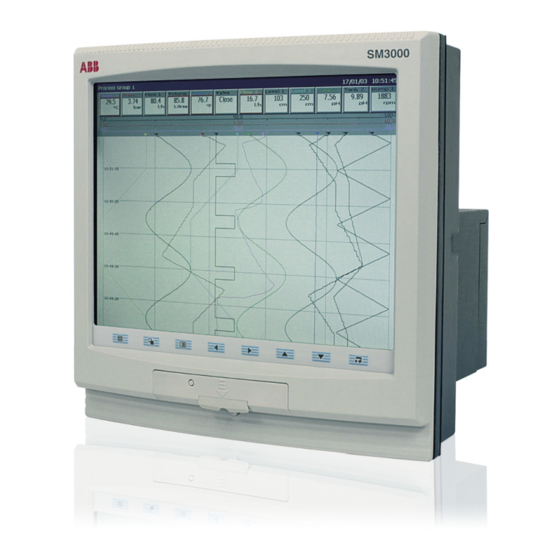
SM3000 Multipoint Videographic Recorder
Product
IM/SM3000
Manual
SM3000
2 Tools Required
•
Medium flat-bladed screwdriver
•
No.2 Pozidriv screwdriver
•
Small-bladed screwdriver or pointed instrument
3 Membrane Switch Sub-Assembly Replacement –
Figs. 3.1 and 3.2
Q
y t
Caution. The
1
electrostatic damage. Wear an anti-static strap or dismantle
1
the unit on an anti-static workbench.
7
1) Isolate the instrument from the power supply.
1
2) Remove the instrument from its case – see Fig. 3.1.
1
2
Unscrew the jacking screw
2
securing the instrument to
the case
Remove tamper-proof
1
seal, if fitted
INFORMATION
instrument
is
vulnerable
Information. Refitting is the
reverse of removal.
to
Continued...
1
Advertisement

Related Manuals for ABB SM3000


Summary of Contents for ABB SM3000
- Page 1 This information sheet describes the procedure for replacing the • Medium flat-bladed screwdriver • No.2 Pozidriv screwdriver SM3000 instrument's Membrane Switch sub-assembly, which is an integral part of the Display Molding. • Small-bladed screwdriver or pointed instrument , GR2000/3710, Membrane Switch Sub-assembly Pack includes the following items: 3 Membrane Switch Sub-Assembly Replacement –...
- Page 2 …3 Membrane Switch Sub-Assembly Replacement – Figs. 3.1 to 3.3 3) Stand the instrument on a protective surface to prevent damage to the exterior finish and screen. 4) Remove the chassis from the display molding – see Fig. 3.2. Disconnect Lay instrument face membrane switch down on a protective...
- Page 3 …3 Membrane Switch Sub-Assembly Replacement – Figs. 3.1 to 3.3 5) Disassemble the display molding – see Fig. 3.3 Remove screws Remove screws (2 off) securing (3 off) securing lower bracket upper bracket and remove and remove bracket bracket Remove jacking …...
- Page 4 ABB has Sales & Customer Support expertise in The Company’s policy is one of continuous product improvement and the right is reserved to modify the over 100 countries worldwide information contained herein without notice. www.abb.com Printed in UK (06.08) © ABB 2008 ABB Limited ABB Inc.
Need help?
Do you have a question about the SM3000 and is the answer not in the manual?
Questions and answers