Hoymiles MI-1000 Manual
Hide thumbs
Also See for MI-1000:
- Installation training (24 pages) ,
- User manual (23 pages) ,
- Quick installation manual (2 pages)
Table of Contents
Advertisement
Quick Links
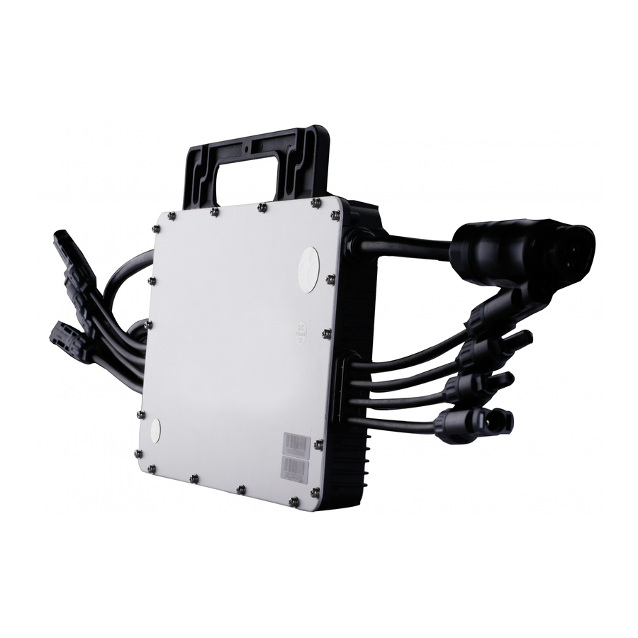
1. Accessories
Item
A
AC End Cable (Female), 2m 12AWG Cable
B
C
D
*Note: All accessories above are not included in the package, and need to be purchased
separately. Please contact our sales representative for the price. (M8 screws need to be
prepared by installer-self.)
2. Installation Steps
Please make sure the microinverter is installed under the required environment.
(Please refer to product user manual for more details.)
Step 1. Fix Microinverter on the Rail
A) Mark the approximate center of each panel on the frame.
B) Fix the screw on the rail.
C) Hang the microinverter on the screw (shown as picture below), and tighten the screw.
The silver cover side of the microinverter should be facing the panel.
MI-1000/MI-1200/MI-1500
Description
M8*25 screws
DC Extension Cable, 1m
AC Female End Cap, IP67
AP040160 REV2.2
Quick Installation Guide
*Note: Please install the microinverter at least 50cm above the ground/roof for better
communication with Hoymiles DTU.
Step 2. Connect AC Cables of Microinverter
A) Plug the AC connector of the first microinverter with the connector of the second
microinverter, to form a continuous AC branch circuit.
*Note: The length of AC cable on microinverter is around 2.06m. If the distance between two
microinverters is more than 2.04m, please use the AC extension cable between two inverters
(As picture indicated below).
B) Install the AC end cap on the open AC connector of the last microinverter in the AC
branch circuit.
Step 3. Connect AC End Cable
A) Make the AC end cable.
1. Take the AC port apart into 3 parts:
1 / 2
Advertisement
Table of Contents

Related Manuals for Hoymiles MI-1000


Summary of Contents for Hoymiles MI-1000
- Page 1 1. Accessories *Note: Please install the microinverter at least 50cm above the ground/roof for better communication with Hoymiles DTU. Step 2. Connect AC Cables of Microinverter A) Plug the AC connector of the first microinverter with the connector of the second microinverter, to form a continuous AC branch circuit.
- Page 2 HMP Online Registration to install the DTU and set up your monitoring system. B) Affix the serial number label to the respective location on the installation map. Product information is subject to change without notice. (Please download reference manuals at www.hoymiles.com.) MI-1000/MI-1200/MI-1500 AP040160 REV2.2...
Need help?
Do you have a question about the MI-1000 and is the answer not in the manual?
Questions and answers