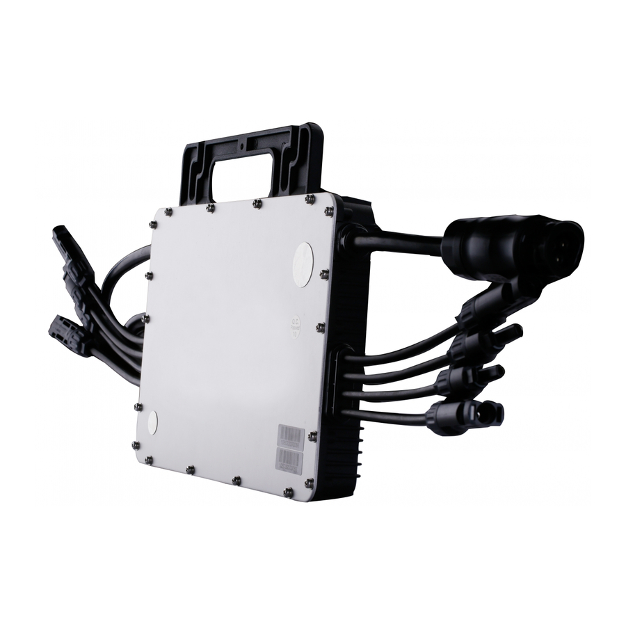
Hoymiles MI-1000 User Manual
Microinverter
Hide thumbs
Also See for MI-1000:
- Installation training (24 pages) ,
- User manual (23 pages) ,
- Manual (2 pages)
Table of Contents
Advertisement
Quick Links
Advertisement
Table of Contents

Subscribe to Our Youtube Channel
Related Manuals for Hoymiles MI-1000


Summary of Contents for Hoymiles MI-1000
- Page 1 MI-1000 /MI-1200 User Manual MICROIVERTER (Model: MI-1000 /MI-1200)
-
Page 2: Table Of Contents
MI-1000 /MI-1200 Table of Contents About this User Manual ......................... 2 Important Safety Instructions ......................3 Symbol Illustration .......................... 3 Installation Warnings ......................4 Prepare for Installing ........................5 Transport and Inspect ......................5 Check Installation Environment ..................6 Installation Position ......................6 Mounting and Wiring ........................ -
Page 3: About This User Manual
MI-1000 /MI-1200 About this User Manual Thank you for using Hoymiles’ MI-1000 /MI-1200 Microinverter! This Microinverter system is the world’s most technologically advanced inverter system in the world with benefits of efficient, flexible, safe and reliable for use in utility-interactive applications. -
Page 4: Important Safety Instructions
MI-1000 /MI-1200 Important Safety Instructions Symbol Illustration The safety symbols in this user manual are show as below. Symbol Usage Indicates a hazardous situation that can result in deadly electric shock hazards, other serious physical injury, or fire hazards. Indicates directions which must be fully understood and followed in entirety in order to avoid potential safety hazards including equipment damage or personal injury. -
Page 5: Installation Warnings
Do not use the equipment if any operating anomalies are found. Avoid temporary repairs. All repairs should be carried out using only qualified spare parts, which must be installed in accordance with their intended use and by a licensed contractor or authorized Hoymiles service representative. ... -
Page 6: Prepare For Installing
Prepare for Installing Transport and Inspect Hoymiles packages and protects individual components using suitable means to make the transport and subsequent handling easier. Transportation of the equipment, especially by road, must be carried out by suitable ways for protecting the components (in particular, the electronic components) from violent, shocks, humidity, vibration, etc. -
Page 7: Check Installation Environment
MI-1000 /MI-1200 Check Installation Environment Installation is carried out based on the system design and the place in which the equipment is installed. The installation must be carried out with the equipment disconnected from the grid (power disconnect switch open) and with the photovoltaic modules shaded or isolated. -
Page 8: Mounting And Wiring
MI-1000 /MI-1200 Fig.1 Installation position of microinverter Mounting and Wiring Installing Diagram System Wiring Diagram (a) Single phase wiring diagram www.hoymiles.com... - Page 9 MI-1000 /MI-1200 (b) Three phase wiring diagram Fig.2 MI-1000 /MI-1200 Microinverter wiring diagram DTU connects the power production of each microinverter. If the asymmetry current is going to exceed 16 A, DTU will send stop signal to one or more microinverters to let the asymmetry current lower than 16A.
-
Page 10: Assembly Instruction
MI-1000 /MI-1200 Assembly Instruction Step 1. Install Microinverter a. Mark the approximate center of each panel on the frame. b. Install the microinverter shown as below. The silver cover side should be up. Observe the certification documents concerning the maximum number of Micro-... -
Page 11: Step 4. Connect Ac End Cable
All the external connections to the insulated junction box (caps, adapters, etc.) must be made with securely-sealed Hoymiles components. Pay special attention and ensure not to reverse the phase with the neutral! The installation technician is responsible for selecting a junction box with the appropriate dimensions and insulation. -
Page 12: Step 6. Connect Pv Modules
MI-1000 /MI-1200 Note: the DC inputs of MI-1000/MI-1200 are identified by 1,2 and 3,4. The left input is 1,2 and the right one is 3,4, shown as above. Affix the serial number label to the respective location on the installation map. -
Page 13: Step 7. Energize The System
MI-1000 /MI-1200 c. Check the LED on the side of the microinverter. The LED flashes six times at start up. All green flashes indicate normal start up. The recommended installation need keeping the Microinverters underneath the photovoltaic modules, so that the Microinverters can operate in the shade. Direct sunlight may cause damage to the Microinverters. -
Page 14: Troubleshooting
MI-1000 /MI-1200 Troubleshooting Qualified personnel can use the following troubleshooting steps if the PV system does not operate correctly. Status Indications and Error Reporting Startup LED Operation Five short green blinks when DC power is first applied to the microinverter indicate a successful microinverter startup. -
Page 15: Troubleshoot An Inoperable Microinverter
5. Check the DC connections between the microinverter and the PV module. 6. Verify the PV module DC voltage is within the allowable range shown in appendix Technical Data of this manual. 7. If the problem persists, please call Hoymiles customer support. Warning ... -
Page 16: Maintenance Guide
MI-1000 /MI-1200 Maintenance Guide Routine Maintenance Only authorized personnel are allowed to carry out the maintenance operations and are responsible to report any anomalies. Always use the personal protective equipment provided by the employer when carry out the maintenance operation. -
Page 17: Storage And Dismantling
MI-1000 /MI-1200 Storage and Dismantling If the equipment is not used immediately or is stored for long periods, check that it is correctly packed. The equipment must be stored in well-ventilated indoor areas that do not have characteristics that might damage the components of the equipment. -
Page 18: Appendix
MI-1000 /MI-1200 Appendix Grid Friendly Functions Protection Settings against electricity system faults Protective function Symbol Setting Trip time Overvoltage (step 2) U>> 264.5 Overvoltage (step 1) U> 253.0 Undervoltage (step 1) U< 195.5 Undervoltage (step 2) U<< 184.0 Overfrequency f>... - Page 19 MI-1000 /MI-1200 Model MI-1000 Input data(DC) Recommended input power (W) 240~380 MPPT voltage range (V) 27~48 Start-up voltage (V) Operating voltage range (V) 16~60 Maximum input voltage (V) Maximum input current (A) 10.5 Output Data (AC) @230V AC @240V AC...
- Page 20 MI-1000 /MI-1200 Model MI-1200 Input data(DC) Recommended input power (W) 240~380 MPPT voltage range (V) 32~48 Start-up voltage (V) Operating voltage range (V) 16~60 Maximum input voltage (V) Maximum input current (A) 10.5 Output Data (AC) @230V AC @240V AC...
-
Page 21: Installation Map
MI-1000 /MI-1200 Installation Map www.hoymiles.com... -
Page 22: Accessories Details
MI-1000 /MI-1200 Accessories Details Accessories Name Function Applicable models Picture Provide extended connection between microinverter & PV model; DC Extension Cable MI1000/1200 With x1 MC4 male and x1 MC4 female connector. AC Extension Cable To extend cable length; with male connector and female connector.
Need help?
Do you have a question about the MI-1000 and is the answer not in the manual?
Questions and answers