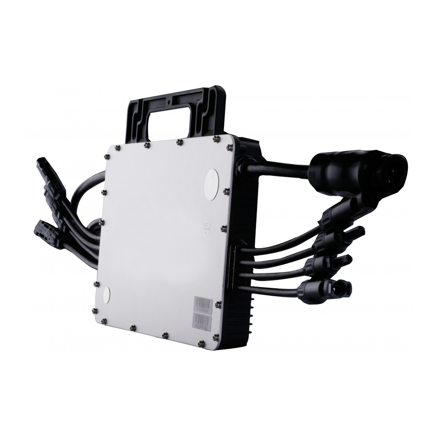
Hoymiles MI-1000 Installation Training
Microinverter system
Hide thumbs
Also See for MI-1000:
- User manual (23 pages) ,
- Manual (2 pages) ,
- Quick installation manual (2 pages)
Subscribe to Our Youtube Channel
Summary of Contents for Hoymiles MI-1000
- Page 1 Hoymiles Microinverter System Installation Training Presented by: Wojciech Kwasniak E-mail: wojciech.kw@hoymiles.com...
- Page 2 Premise Prepare for the installation of microinverter system The process of microinverter system installation Installation Pictures...
- Page 3 Popular Products MI-1000/1200 MI-500/600/700 MI-250/300...
- Page 4 Equipments AC Female Panel Connector Rail AC End Cap Microinverter AC End Cable Data Transfer Distribution Box Unit / DTU...
-
Page 5: Required Tools For Installation
Required Tools for Installation Double-headed Hexagon Multi-function wrench wrench(13-15) Adjustable wrench Screwdriver Multimeter... - Page 6 Microinverter Installation steps...
- Page 7 1 Install Microinverter a. Mark the approximate center of each panel on the frame. b. Install the microinverter shown as below. The silver cover side should be up Silver cover side up.
- Page 8 2 Install AC Junction Box a. Install an AC junction box at the suitable location on the racking. b. Provide an AC connection from the AC junction box back to the electricity network connection using equipment and practices as required by local jurisdictions.
- Page 9 3 Connect AC Cables of Microinverter a. Plug the AC connector of the first microinverter into the connector of the next microinverter, and so forth, to form a continuous AC branch circuit a. Install the AC End Cap on the open AC connector of the last microinverter in the AC branch circuit...
- Page 10 4 Connect AC End Cable a. Connect the AC End Cable connector to the adjacent microinverter connector. b. Connect AC End Cable to the junction box and wire with the cable to the electricity network. Close the junction box after the wiring is complete. Note: Brown Wire: L Blue Wire: N Yellow/Green Wire: Ground...
- Page 11 5 Create an Installation Map a. Peel the removable serial number label from each microinverter. The position of the label is shown as below. Note: the DC inputs of MI-500 are identified by A and B. The left input is A and the right one is B, shown as above.
- Page 12 b. Affix the serial number label to the respective location on the installation map. Note: the serial number label of MI-500 should be affixed between two blanks and mark A and B to identify the two connected PV panels.
- Page 13 6 Connect PV Modules a. Mount the PV modules above the microinverters b. Connect the DC cables of the modules to the DC input side of the microinverter.
- Page 14 c. Check the LED on the side of the microinverter. The LED flashes six times at start up. All green flashes indicate normal start up.
- Page 15 7 Energize the System a. If applicable, turn on the AC disconnect or circuit breaker for the branch circuit. b. Turn on the main utility-grid AC circuit breaker. Your system will start producing power after about two-minute wait time.
- Page 16 8 System Monitoring Set Up • Refer to the DTU User Manual or the DTU Quick Install Guide to install the DTU and set up system monitoring.
- Page 17 Distribution box installation 1. In principle, the distribution box shall be close to the meter of the user. The installation position shall be safe, firm and easy to operate. (If local power sector has requirements, do as they requested); 2. The distribution box should be installed in the place to avoid rain and exposure, the minimum height can not be less than 1600mm.
- Page 18 Grounding Pile DTU-MI-GPRS DTU Setting Platform DTU-GPRS-MI can connect 99 pieces microinverters' ID;...
-
Page 19: Dtu Installation
DTU installation 1. Installation environment (1) Dry non-corrosive liquids and heat objects; (2) With 220V power supply; (3) LAN network support (GPRS Internet card provides network version except). 2. Installation location (1) Installed in the router near the LAN network connection (GPRS Internet card provides network version except);... - Page 20 DTU Internet Connection Status Confirm whether the installation is successful (1) The network power, confirm LCD NC / LC change to YC. YC said that the server has been connected successfully.
- Page 21 Module monitoring type Computer, mobile real-time monitoring, big data management. Achieve module-level monitoring, real-time control of each module's power generation status, quickly locate the location of the fault, the remote upgrade program to adapt to the situation of local power grid...
- Page 22 Installation Pictures...
- Page 23 Installation Pictures...
- Page 24 THANK YOU Leading Solar Energy by a Trustable Way www.hoymiles.com...


Need help?
Do you have a question about the MI-1000 and is the answer not in the manual?
Questions and answers