Hoymiles MI-1200 User Manual
Microinverter
Hide thumbs
Also See for MI-1200:
- User manual (29 pages) ,
- Installation training (24 pages) ,
- Manual (2 pages)
Advertisement
Advertisement
Table of Contents

Related Manuals for Hoymiles MI-1200


Summary of Contents for Hoymiles MI-1200
- Page 1 MICROINVERTER User Manual (Model: MI-1200 /MI-1000) for North America Rev 1.0...
- Page 2 Microinverter user manual Contact Information Hoymiles Converter Technology Co., Ltd. No.18 Kangjing Road, Hangzhou, Zhejiang Province, China www.hoymiles.com info@hzconverter.com...
- Page 3 FCC Compliance This equipment has been tested and found to comply with the limits for a Class B digital device, pursuant to part 15 of the FCC Rules. These limits are designed to provide reasonable protection against harmful interference in a residential installation.
- Page 4 Microinverter user manual Le pr¨|sent appareil est conforme aux CNR d'Industrie Canada applicables aux appareils radio exempts de licence. L'exploitation est autoris¨|e aux deux conditions suivantes: (1) l'appareil ne doit pas produire de brouillage, et (2) l'utilisateur de l'appareil doit accepter tout brouillage radioélectrique subi, même si le brouillage est susceptible d'en compromettre le fonctionnement.
-
Page 5: Table Of Contents
Microinverter user manual CONTENTS 1. IMPORTANT SAFETY INFORMATION........4 1.1. SAFETY INSTRUCTIONS AND WARNINGS....4 1.2. SYMBOLIC INTERPRETATION.......... 5 1.3. PV RAPID SHUTDOWN EQUIPMENT (PVRSE).... 6 2. INTRODUCTION................7 3. SYSTEM INSTALLATION............9 3.1. PREPARE FOR INSTALLING..........9 3.2. ASSEMBLY INSTRUCTION..........9 4. TECHNICAL DATA..............14 5. -
Page 6: Important Safety Information
(7) Do not immerse the microinverter and connector in the liquid and expose it to the oriented, pressurized liquid (spray, etc.,). (8) Do not try to repair Hoymiles microinverter by yourself. If there is a breakdown, please contact Hoymiles customer services. -
Page 7: Symbolic Interpretation
Microinverter user manual than that specified in the operating instructions. CAUTION - To reduce the risk of fire, connect only to a circuit provided with branch circuit overcurrent protection in accordance with the National Electrical Code, ANSI/NFPA 70. 1.2. SYMBOLIC INTERPRETATION 1) The safety symbols used in this manual are list below and illustrated in detail. -
Page 8: Pv Rapid Shutdown Equipment (Pvrse)
Microinverter user manual 2) The symbols on the microinverter are list below and illustrated in detail. Symbol Usage Caution Do not come within 8 inches (20cm) of the microinverter for any length of time while it is in operation. Danger of high voltages Danger to life due to high voltage in the microinverter. -
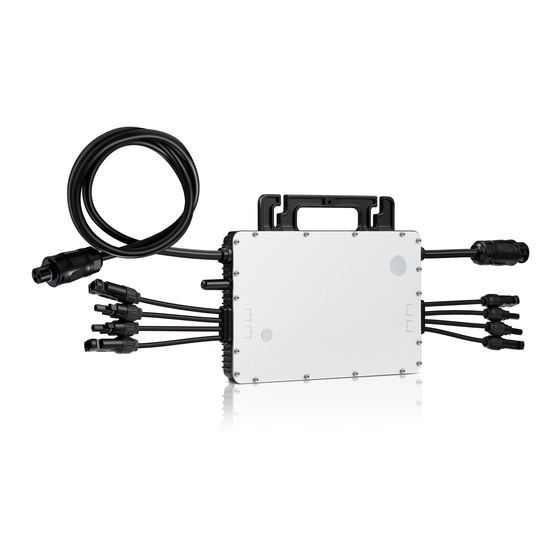
Page 9: Introduction
Refer to NEC or CSA C22.1-2015 for more information. 2. INTRODUCTION Hoymiles microinverter system is shown in the figure below. The whole system consists of two parts, PV grid-connected power generation unit and PV monitoring unit. PV grid-connected power generation units include PV modules, microinverters, AC wiring harnesses and other system accessories;... - Page 10 2.4G RF and the microinverter communication, collect the real-time operating data of the microinverter, and transmit the collected microinverter data to Hoymiles remote monitoring server via Ethernet. Remote monitoring server: Collects the operating data and status of each...
-
Page 11: System Installation
Cross screwdriver 3.2. ASSEMBLY INSTRUCTION The installation diagram of MI-1200/MI-1000 microinverter is shown in the figure below. One microinverter connects with four panels and places in the middle of them, the junction box of the four panels must be placed close to the... - Page 12 Microinverter user manual Assembly Illustration Step 1. Install Microinverter a. Mark the approximate center of each panel on the frame. b. Install the microinverter shown as below. The silver cover side should be up. Step 2. Install AC Junction Box a.
- Page 13 Microinverter user manual required by local jurisdictions. Step 3. Connect AC Cables of Microinverter a. Plug the AC connector of the first microinverter into the connector of the next microinverter, and so forth, to form a continuous AC branch circuit b.
- Page 14 Microinverter user manual Note:the DC inputs of MI-1000 or MI-1200 are identified by 1,2 and 3,4. The left input is 1,2 and the right one is 3,4, shown as above. Affix the serial number label to the respective location on the installation map.
- Page 15 Microinverter user manual b. Connect the DC cables of the modules to the DC input side of the microinverter. c. Check the LED on the side of the microinverter. The LED flashes six times at start up. All green flashes indicate normal start up. Indicator flashing situation Microinverter working condition Flashing green light...
-
Page 16: Technical Data
Microinverter user manual Green light flashes slowly Microinverter works normally but (4s interval) the communication with the DTU is abnormal Red light flashes Grid anomaly (1s interval) Step 7. Energize the System a. If applicable, turn on the AC disconnect or circuit breaker for the branch circuit. - Page 17 Microinverter user manual Output Data (AC) Rated output power (W) 1000 Rated output current (A) 4.17@240V a.c.,4.81@208V a.c. Nominal output voltage/range (V) 240/211.2-264,208/183-228.8 Nominal frequency/range (Hz) 60/59.3-60.5 Power factor >0.99 Output current harmonic distortion <3% Max. inverter backfeed current to the array (A) Maximum output overcurrent protection (A)
- Page 18 PV arrays in NEC 690.35. Features Communication Wireless Design Life >25 years Volatage and frequency ranges can be extended beyond nominal if required by the utility Model MI-1200 Input data(DC) Recommended input power (W) 4*200~350 MPPT voltage range (V) 32~48...
- Page 19 Microinverter user manual Operating voltage range (V) 16~60 Maximum input voltage (V) Maximum input current (A) 4*10.5 Maximum short circuit current limit (A) 4*15 Output Data (AC) Rated output power (W) 1200 Rated output current (A) 5.00@240V a.c.,5.77@208V a.c. Nominal output voltage/range (V) 240/211.2-264, 208/183-228.8 Nominal frequency/range (Hz) 60/59.3-60.5...
- Page 20 Microinverter user manual Mechanical Data Ambient temperature range (℃) -40 ~ +65 -40 ~ +85 Storage temperature range (℃) Relative humidity (%RH) 0-100% condensing Maximum operating altitude without 2000 derating (m) Dimensions (W×H×D mm) 280×176×33 Weight (kg) 3.75 Enclosure rating Type 6, outdoor use Cooling Natural convection –...
-
Page 21: Installing Diagram
Microinverter user manual 5. INSTALLING DIAGRAM System Wiring Diagram (a) 120 / 240Vac split single phase wiring diagram (b) 120 /208 Vac three phase wiring diagram Fig.2. MI-1000 /MI-1200 Microinverter wiring diagram... -
Page 22: Installation Map
Microinverter user manual 6. INSTALLATION MAP... - Page 23 Microinverter user manual...
Need help?
Do you have a question about the MI-1200 and is the answer not in the manual?
Questions and answers