Hoymiles MI-1000 User Manual
Microinverter
Hide thumbs
Also See for MI-1000:
- Installation training (24 pages) ,
- User manual (22 pages) ,
- Manual (2 pages)

Subscribe to Our Youtube Channel
Related Manuals for Hoymiles MI-1000


Summary of Contents for Hoymiles MI-1000
- Page 1 MI-1000/MI-1200/MI-1500 User Manual User Manual MICROI MICROINVERTER (Model: MI (Model: MI-1000/MI-1200/MI-1500)
- Page 2 About the manual This manual contains important instructions for the MI-1000/MI-1200 Microinverter and must be read in its entirety before installing or commissioning the equipment. For safety, only qualified technician, who has received training or has demonstrated skills can install and maintain this Microinverter under the guide of this document.
-
Page 3: Table Of Contents
MI-1000/MI-1200/MI-1500 Contents 1. Important Notes ............................. 5 1.1 Product Range............................. 5 1.2 Target Group ..............................5 1.3 Symbols Used .............................. 5 2. About Safety ............................6 2.1 Important Safety Instructions ........................ 6 2.2 Explanation of Symbols ........................... 7 3. About Product ............................7 3.1 About 4 in 1 unit ............................ -
Page 4: Important Notes
MI-1000/MI-1200/MI-1500 1. Important Notes 1.1 Product Range This manual describes the assembly, installation, commissioning, maintenance and failuresearch of the following model of Hoymiles Microinverter: MI-1000 MI-1200 MI-1500 Note: “1000” means 1000W, “1200” means 1200W, “1500” means 1500W. -
Page 5: About Safety
Do not use the equipment if any operating anomalies are found. Avoid temporary repairs. All repairs should be carried out using only qualified spare parts, which must be installed in accordance with their intended use and by a licensed contractor or authorized Hoymiles service representative.... -
Page 6: Explanation Of Symbols
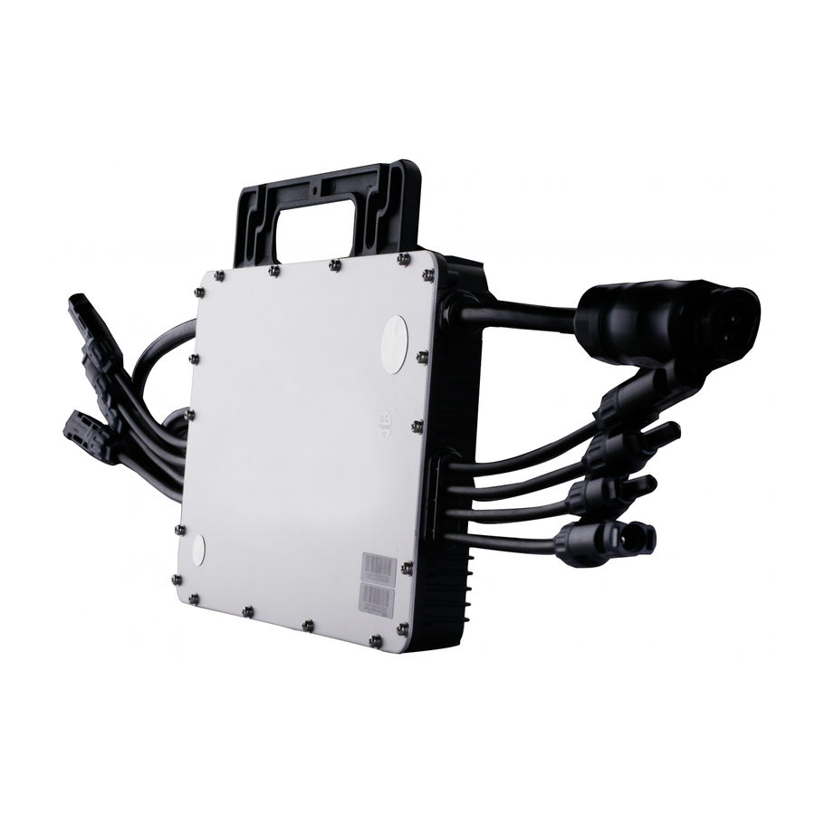
Hoymiles 4 in 1 Microinverter MI-1000/MI-1200/MI-1500 is “The Best PowerDensity Microinverter” ever in solar industry with extremely light weight-only3.75KG including integrated DC&AC cables;3-phase wiring is also easy to be configured by Hoymiles 4 in 1 Microinverter for MW size commercial PV power stations(one of the world’s... -
Page 7: Highlights
MI-1000/MI-1200/MI-1500 3.2 Highlights Maximum output power up to 1000/1200/1500W; Adapted to 60 & 72 cells PV panels. Peak efficiency 96.60%; CEC weighted efficiency 96.50%. Static MPPT efficiency 99.80%; Dynamic MPPT efficiency 99.76% in overcast weather. High reliability: NEMA6 (IP67) enclosure; 6000V surge protection. -
Page 8: Dimension
MI-1000/MI-1200/MI-1500 3.4 Dimension 4. Function 4.1 Work Mode Normal: Under this mode, Microinverter is operating normally and convert DC power into AC power to support the house loads and feed in to Public Grid. Anti-reflux Control: Under this mode Microinverter’s generation is limit base on the current house loads, there will be no extra power feed in to the Public Grid. -
Page 9: Installation
MI-1000/MI-1200/MI-1500 Object Description AC Extension Cable AC End Cable (Female) , 2m 12 AWG cable. AC Female Connector DC Male Connector AC Male End Cap, IP67. AC Female End Cap, IP67. Screw, 2 pcs of M8*25 screws to tighten Microinverter on the frame. -
Page 10: Space Distance Required 图片
MI-1000/MI-1200/MI-1500 5.3 Space Distance Required Please install the Microinverter at least 500mm above the ground/roof. Please contact with Hoymiles Tech. engineer if there is any special circumstance. -
Page 11: Preparation
MI-1000/MI-1200/MI-1500 5.4 Preparation Installation of the equipment is carried out based on the system design and the place in which the equipment is installed. The installation must be carried out with the equipment disconnected from the grid (power disconnect switch open) and with the photovoltaic modules shaded or isolated. -
Page 12: Installation Steps
MI-1000/MI-1200/MI-1500 Fig.1 InstallationPosition of Microinverter 5.5 Installation Steps Step 1. Install Microinverter a.Mark the approximate center of each panel on the frame. b. Install the Microinverter shown as below two methods. The silver cover side should be up. Method 1: Secure with 1 screw... - Page 13 MI-1000/MI-1200/MI-1500 c. Tighten the screw crew and fix the inverter on the frame (for method 2 on the frame (for method 2 only). Observe the certification documents concerning the maximum number of Observe the certification documents concerning the maximum number of...
- Page 14 MI-1000/MI-1200/MI-1500 Step 4. Create an Installation Map Peel the removable serial number label from each microinverter(The position of the label is shown as below). Affix the serial number label to the respective location on theinstallation map (Please refer to the appendix for the installation map).
- Page 15 MI-1000/MI-1200/MI-1500 a. Mountthe PV modules above themicroinverters. b. Connect the PV modules’ DC cablesto theDCinputsideofthemicroinverter. The recommended installation need to keep the Microinverter underneath the photovoltaic modules, so that the Microinverters can operate in the shadow. Direct sunlight exposure may effect on the performance as well as the lifetime to the Microinverter.
-
Page 16: Troubleshooting
MI-1000/MI-1200/MI-1500 6. Troubleshooting 6.1 Troubleshooting List Status Code Solution Please contact your installer. Please contact your installer. Waiting for AC voltage recover, if the code appears frequently please contact your installer to check the AC wiring. Please Contact your installer, and provide Panel specs. - Page 17 5. Check the DC connections between the microinverter and the PV module. 6. Verify the PV module DC voltage is within the allowable range shown in appendix Technical Data of this manual. 7. If the problem persists, please call Hoymiles customer support. Warning ...
- Page 18 MI-1000/MI-1200/MI-1500 During normal operation, check that the environmental and logistic conditions are correct. Make sure that the conditions have not changed over time and that the equipment is not exposed to adverse weather conditions and has not been covered with foreign bodies.
-
Page 19: Sample Wiring Diagram
MI-1000/MI-1200/MI-1500 7. Sample Wiring Diagram Sample Wiring Diagram Fig.2SinglePhase Wiring Diagram Fig.3 Three phase wiring diagram DTU connects the power production of each microinverter. If the DTU connects the power production of each microinverter. If the DTU connects the power production of each microinverter. If the asymmetry... -
Page 20: Decommissions
5kg weight and can be fully closed if the original packaging is no longer available. 8.2 Storage and Transportation Hoymiles packages and protects individual components using suitable means to make the transport and subsequent handling easier. Transportation of the equipment, especially by road, must be carried out by suitable ways for protecting the components (in particular, the electronic components) from violent, shocks, humidity, vibration, etc. -
Page 21: Technical Data
MI-1000/MI-1200/MI-1500 9. Technical Data Model MI-1000 MI-1200 MI-1500 Recommended input power (W) MPPT voltage range (V) 27~48 32~48 36~48 Start-up voltage (V) Operating voltage range (V) 16~60 16~60 16~60 Maximum input voltage (V) Maximum input current (A) 10.5 10.5 11.5 9.1 DC Input... -
Page 22: Efficiency, Safety And Protection
MI-1000/MI-1200/MI-1500 Model MI-1000 MI-1200 MI-1500 Peak inverter efficiency 96.60% 96.60% 96.60% CEC weighted efficiency 96.50% 96.50% 96.50% Nominal MPPT efficiency 99.80% 99.80% 99.80% Night time power consumption (mW) <50 <50 <50 9.3 Efficiency, Safety and Protection 9.4 General Data Model... -
Page 23: Installation Map
MI-1000/MI-1200/MI-1500 Appendix 1: Installation Map...
Need help?
Do you have a question about the MI-1000 and is the answer not in the manual?
Questions and answers