Table of Contents
Advertisement
Quick Links
Advertisement
Table of Contents
Troubleshooting

Subscribe to Our Youtube Channel
Related Manuals for Hoymiles MI-1000N


Summary of Contents for Hoymiles MI-1000N
- Page 1 Version 1.1 (June 2020)
- Page 2 About the Manual This manual contains important instructions for the MI-1000N/MI-1200N/MI-1500N Microinverter and must be read in its entirety before installing or commissioning the equipment. For safety, only qualified technician, who has received training or has demonstrated skills can install and maintain this Microinverter under the guide of this document.
-
Page 3: Table Of Contents
6.5 On-site Inspection (For qualified installer only) ..................22 6.6 Routine Maintenance ..........................22 6.7 Replace Microinverter ..........................23 7. Decommissions ..............................24 7.1 Decommissions ............................24 7.2 Storage and Transportation ........................24 © 2019 Hoymiles Converter Technology Co., Ltd. All rights reserved. - Page 4 Appendix 1: ................................28 Installation Map ..............................28 Appendix 2: ................................29 WIRING DIAGRAM –120VAC / 240VAC SPLIT PHASE: ................29 WIRING DIAGRAM – 120VAC / 208VAC THREE PHASE: ............... 30 © 2019 Hoymiles Converter Technology Co., Ltd. All rights reserved.
-
Page 5: Important Notes
2. About Safety 2.1 Important Safety Instructions The MI-1000N/MI-1200N/MI-1500N Microinverter is designed and tested according to international safety requirements. However, certain safety precautions must be taken when installing and operating this inverter. The installer must read and follow all instructions, cautions and warnings in this installation manual. -
Page 6: Explanation Of Symbols
Ø Do not use the equipment if any operating anomalies are found. Avoid temporary repairs. Ø All repairs should be carried out using only qualified spare parts, which must be installed in accordance with their intended use and by a licensed contractor or authorized Hoymiles service representative. -
Page 7: Radio Interference Statement
“The world’s First Daisy-Chain 4 in 1 Unit Microinverter” with extremely wide DC input operating voltage range (16-60V) and low start-up voltage (22V only). Hoymiles 4 in 1 unit Microinverter MI-1000N/MI-1200N/MI-1500N is the perfect selection for PV © 2019 Hoymiles Converter Technology Co., Ltd. All rights reserved. -
Page 8: Highlights
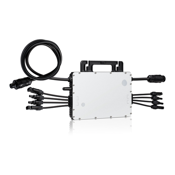
Static MPPT efficiency 99.80%; Dynamic MPPT efficiency 99.76% in overcast weather. High reliability: NEMA6 (IP67) enclosure; 6000V surge protection. 3.3 Terminals Introduction Object Description AC Connector (male) AC Connector (Female) DC Connectors 3.4 Dimension(mm) © 2019 Hoymiles Converter Technology Co., Ltd. All rights reserved. -
Page 9: About Function
*Note: All accessories above are not included in the package, and need to be purchased separately. Please contact our sales representative for the price. (M8 screws need to be prepared by installer-self.) © 2019 Hoymiles Converter Technology Co., Ltd. All rights reserved. -
Page 10: Installation Precaution
DTUs and the microinverters. 5.4 Preparation Installation of the equipment is carried out based on the system design and the place in which the equipment is installed. © 2019 Hoymiles Converter Technology Co., Ltd. All rights reserved. -
Page 11: Installation Steps
If this condition cannot be met, might trigger the inverter production de-rating. Fig.1 Installation position of microinverter 5.5 Installation Steps Step 1. Fix Microinverter on the Rail A) Mark the approximate center of each panel on the frame. © 2019 Hoymiles Converter Technology Co., Ltd. All rights reserved. - Page 12 B) Install the AC end cap on the open AC connector of the last microinverter in the AC branch circuit. Step 3. Connect AC End Cable Make the end cable 1. Take the AC port apart into 3 parts: © 2019 Hoymiles Converter Technology Co., Ltd. All rights reserved.
- Page 13 C) Connect the other side of the AC end cable to the distribution box, and wire it to the local grid network. Step 4. Create an Installation Map A) Peel the removable serial number lable from each microinverter (The position of the label is shown as below.) © 2019 Hoymiles Converter Technology Co., Ltd. All rights reserved.
- Page 14 B) Affix the serial number label to the respective location on the installation map. Step 5. Connect PV Modules Mount the PV modules above the microinverter. B) Connect the PV modules’ DC cables to the DC input side of the microinverter. © 2019 Hoymiles Converter Technology Co., Ltd. All rights reserved.
-
Page 15: Troubleshooting
6.3. If you use the microinverter of serial number “1060xxxxxxxx” and “1061xxxxxxxx”, please refer to chapter 6.2 and chapter 6.4. *Note: The microinverter of serial number “1062xxxxxxxx” can only work with the new Hoymiles gateway, DTU-Pro (SN: 10F7xxxxxxxx, 10F8xxxxxxxx), DTU-G100 (SN: 10D2xxxxxxxx) and DTU-W100 (SN: 10D3xxxxxxxx). - Page 16 2. If the alarm occurs frequently, check whether the grid voltage is within the acceptable range. If no, contact the local power operator or change the grid overvoltage protection limit via Hoymiles monitoring system with the consent of the local power operator.
- Page 17 2. If the alarm occurs frequently, check whether the grid frequency change rate change rate is within the acceptable range. If no, contact the local power operator or change the grid frequency change rate limit via Hoymiles monitoring system with the consent of the local power operator. Power grid outage Please check whether there is a power grid outage.
- Page 18 2. If the alarm occurs frequently and cannot be recovered, contact your dealer or Hoymiles technical support. Hardware Error Code 1. If the alarm occurs accidentally and the microinverter can still work normally, no special treatment is required. © 2019 Hoymiles Converter Technology Co., Ltd. All rights reserved.
-
Page 19: Troubleshooting List (Sn: 1060Xxxxxxxx, 1061Xxxxxxxx)
1.If the PV input voltage is too high, please make sure that the PV module 5053 Overvoltage/Undervo open-circuit voltage is less than or equal to the maximum input voltage. ltage © 2019 Hoymiles Converter Technology Co., Ltd. All rights reserved. - Page 20 If no, contact the local power operator or change the grid overfrequency or underfrequency protection limit via Hoymiles monitoring system with the consent of the local power operator. 1. If the alarm occurs accidentally, the grid voltage may be abnormal temporarily.
-
Page 21: Status Led Indicator (Sn: 1062Xxxxxxxx)
DTU and microinverter. Then try 5200 Firmware error again. 3. If the fault still exists, contact your dealer or Hoymiles technical support. Please check if the microinverter is turned off by the zero export mode, 8310 Shut down otherwise please contact your dealer. -
Page 22: Status Led Indicator (Sn: 1060Xxxxxxxx, 1061Xxxxxxxx)
ü Flashing Red and Green alternately: Firmware is corrupted. *Note: All the faults are reported to the DTU, refer to the local APP of the DTU or Hoymiles Monitoring Platform for more information. 6.4 Status LED Indicator (SN: 1060xxxxxxxx, 1061xxxxxxxx) The LED flashes six times at start up. -
Page 23: Replace Microinverter
Using a meter to measure and make sure there is no current flowing in the DC wires between panel and microinverter. Ø Use the DC disconnect tool to remove the DC connectors. Ø Use the AC disconnect tool to remove the AC connectors. © 2019 Hoymiles Converter Technology Co., Ltd. All rights reserved. -
Page 24: Decommissions
7.2 Storage and Transportation Hoymiles packages and protects individual components using suitable means to make the transport and subsequent handling easier. Transportation of the equipment, especially by road, must be carried out by suitable ways for protecting the components (in particular, the electronic components) from violent, shocks, humidity, vibration, etc. -
Page 25: Disposal
DC current. But the maximum short circuit current must be equal to or less than the maximum input DC short circuit current. The output DC power of PV module is NOT recommended to exceed 1.35 times the output AC power of the microinverter. Refer to “Hoymiles Warranty Terms & Conditions” for more information. 8.1 DC Input Model... -
Page 26: Ac Output
-40 ~ +85 -40 ~ +85 -40 ~ +85 Dimensions (W×H×D mm) 280 x 176 x 33 Weight (kg) 3.75 3.75 3.75 Enclosure rating Outdoor-NEMA (IP67) Cooling Natural convection – No fans © 2019 Hoymiles Converter Technology Co., Ltd. All rights reserved. -
Page 27: Features
Confirms with NEC-2014 and NEC-2017 Article PV Rapid Shutdown 690.12 and CEC-2018 Sec 64-218 Rapid Shutdown of PV Systems *Note: Voltage and frequency ranges can be extended beyond nominal if required by the utility. © 2019 Hoymiles Converter Technology Co., Ltd. All rights reserved. -
Page 28: Installation Map
MI-1000N/MI-1200N/MI-1500N Appendix 1: Installation Map © 2019 Hoymiles Converter Technology Co., Ltd. All rights reserved. -
Page 29: Wiring Diagram -120Vac / 240Vac Split Phase
MI-1000N/MI-1200N/MI-1500N Appendix 2: WIRING DIAGRAM –120VAC / 240VAC SPLIT PHASE: © 2019 Hoymiles Converter Technology Co., Ltd. All rights reserved. -
Page 30: Wiring Diagram - 120Vac / 208Vac Three Phase
MI-1000N/MI-1200N/MI-1500N WIRING DIAGRAM – 120VAC / 208VAC THREE PHASE: © 2019 Hoymiles Converter Technology Co., Ltd. All rights reserved.
Need help?
Do you have a question about the MI-1000N and is the answer not in the manual?
Questions and answers