
Related Manuals for Perle C-100MM Series


Summary of Contents for Perle C-100MM Series
- Page 1 Perle Fast Ethernet Fiber to Fiber Media Converter Module Installation Guide C-100MM-XXXXX Unmanaged Module CM-100MM-XXXXX Managed Module P/N 5500313-10...
- Page 2 Overview This document contains instructions necessary for the installation and operation of the Perle Fast Ethernet Fiber to Fiber Media Converter Module(s) (C-100MM and CM-100MM) that are used in conjunction with a Perle MCR chassis. The C-100MM are the unmanaged media converter modules, and the CM-100MM are the managed versions.
- Page 3 40 km/24.9 mi. 1550/1310 nm CM-100MM-S1SC40U C-100MM-S1SC40D 40 km/24.9 mi. 1550/1310 nm CM-100MM-S1SC40D Note: Please refer to Perle’s web site for the most up to date Installation guides, models and specifications http://www.perle.com/ Fast Ethernet Fiber to Fiber Media Module – Installation Guide...
-
Page 4: Installation
The default DIP switch settings (all switches in the UP position) and jumper settings will work for most installations. The following steps are used to configure the Perle Fast Media Converter Module: • Set the Auto-Config jumper. (CM-100MM only) (optional) •... -
Page 5: Dip Switch Settings
DIP Switch Settings Note: All switch changes take effect immediately and will result in a link reset on both fiber ports. Link Mode (Switch 1) Switch Mode Position Up (default) Link Pass-Through Mode Down Standard Mode Link Pass-Through: In this mode, the link state on one fiber connection is directly reflected through the media module to the other fiber connection. - Page 6 Far End Fault (Switch 2) Switch Mode Position Up (default) Enabled Down Disabled Enabled: If the media module detects a loss of fiber signal on the fiber receiver, the media module will immediately send a FEF on the transmitter of its fiber link to the remote end module. This, in effect, notifies the fiber link partner that an error condition exists on the fiber connection.
-
Page 7: Sequence Of Events
Sequence of Events 1. Media module loses fiber connection (RX) on MM2/SM2. 2. Media module sends FEF on transmitter (TX) MM2/SM2. 3. Media module detects loss of fiber link on receiver RX – MM2/SM2. 4. Media module turns off transmitter (TX) on MM1. 5. - Page 8 Failure to observe this caution could result in damage to the module(s) and/or chassis. The Perle media module can be installed in any available slot and in any order within the MCR chassis. •...
- Page 9 Removing Media Convert Modules Loosen the captive retainer screw on the front of the media module and gently pull the module towards you. If not inserting a replacement media module cover the opened slot with a face plate and secure the screw. Installing the Duplex Fiber Cable Locate a 100Base-X compliant duplex (2 strands) fiber cable with the appropriate connectors.
-
Page 10: Operation
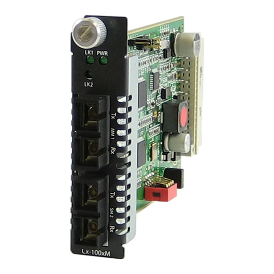
Operation Status LED The Perle Fast Ethernet Media Converter modules have three single colored status LEDs located on the face plate of the module. PWR - Power/Test • On- Power is on, the module is operating normally. • Blinking- slowly: the module is in loopback mode. -
Page 11: Troubleshooting
Troubleshooting General • Ensure the module is correctly seated to the backplane in the MCR chassis. The PWR LED should be on solid. • Ensure all cabling is of the correct type and is in good working order. • Ensure both devices on either end of the fiber are compatible. If using a simplex fiber connection, ensure that you have both an Upstream (U) and Downstream (D) media module. -
Page 12: Technical Specifications
Technical Specifications The following applies to all C-100MM and CM-100MM media converter modules: Power Input/Consumption 12V DC /3.5 W 0°C to 50°C (32°F to 122°F) Operating Temperature: 25°C to 70°C (-13°F to 158°F) Storage Temperature: 5% to 90% non-condensing Operating Humidity: 5% to 95% non-condensing Storage Humidity: Up to 3,048 m (10,000 ft) - Page 13 Max: -3 CM-100MM-S1SC40D Fiber Cabling Requirements 50/125 microns or 62.5/125 microns 9/125 microns Note: Please refer the product page on the Perle website for the most up to date specifications. http://www.perle.com/ Fast Ethernet Fiber to Fiber Media Module – Installation Guide...
-
Page 14: Compliance Information
Compliance Information This product has been found to comply with the limits for a Class A digital device, pursuant to Part 15 of the FCC rules. These limits are designed to provide reasonable protection against harmful interference when the equipment is operated in a commercial environment. -
Page 15: Warranty Registration
Warranty / Registration Perle’s standard Lifetime Warranty provides customers with return to factory repairs for Perle products that fail under the conditions of the warranty coverage. Details can be found at: http://www.perle.com/support_services/warranty.shtml Contacting Technical Support Contact information for the Perle Technical Assistance Center (PTAC) can be found at the link below.
Need help?
Do you have a question about the C-100MM Series and is the answer not in the manual?
Questions and answers