Table of Contents
Advertisement
Quick Links
SCC-SG Series Strain-Gauge
Modules User Guide
Contents
The SCC-SG Series strain-gauge input modules (SCC-SGXX) allow you to
take quarter-, half-, and full-bridge configuration strain measurements. Use
them as follows:
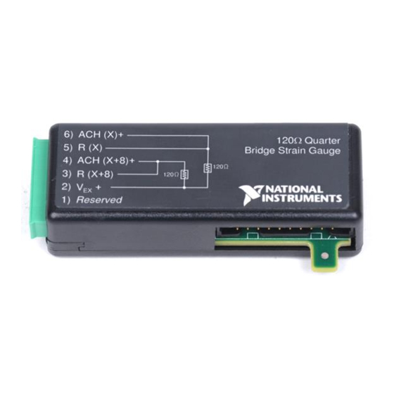
SCC-SG01 for 120 Ω quarter-bridge configurations.
•
SCC-SG02 for 350 Ω quarter-bridge configurations.
•
•
SCC-SG03 for half-bridge configurations.
•
SCC-SG04 for full-bridge configurations.
SCC-SG24 for at least 350 Ω full-bridge configurations.
•
Each module consists of two strain-gauge input channels, offset-nulling
circuitry for each channel, and an excitation circuit. Each input channel
includes an instrumentation amplifier with differential inputs and a fixed
gain of 100.
The SCC-SG11 is a shunt calibration module. It contains two pairs of
switches and resistors that you connect across strain-gauge elements where
you want to perform shunt calibration.
Strain Gauges .......................................................................................... 3
Conventions ............................................................................................ 4
What You Need to Get Started ............................................................... 5
Unpacking the Module............................................................................ 6
Installing the Module .............................................................................. 6
Connecting Strain-Gauge Input Signals.................................................. 7
Panelettes ......................................................................................... 8
SCC-SG0X and SCC-SG24 .................................................................... 8
Variable Definitions......................................................................... 8
SCC-SG01/02 Quarter-Bridge Connection ..................................... 9
Quarter-Bridge Type I .............................................................. 10
SCC-SG03 Half-Bridge Connection................................................ 12
Half-Bridge Type I ................................................................... 12
Advertisement
Table of Contents

Related Manuals for National Instruments SCC-SG Series


Summary of Contents for National Instruments SCC-SG Series
-
Page 1: Table Of Contents
SCC-SG Series Strain-Gauge Modules User Guide The SCC-SG Series strain-gauge input modules (SCC-SGXX) allow you to take quarter-, half-, and full-bridge configuration strain measurements. Use them as follows: SCC-SG01 for 120 Ω quarter-bridge configurations. • SCC-SG02 for 350 Ω quarter-bridge configurations. - Page 2 Converting Voltage Measurements to Units of Strain .....39 Strain Equations................40 Formulas and Variable Definitions ...........41 Quarter-Bridge Type I...............41 Quarter-Bridge Type II..............42 Half-Bridge Type I ..............42 Half-Bridge Type II..............42 Full-Bridge Type I..............42 Full-Bridge Type II ..............43 Full-Bridge Type III ..............43 SCC-SG Series Strain-Gauge Modules User Guide ni.com...
-
Page 3: Strain Gauges
There are three supported types of strain-gauge configurations: quarter-, half-, and full-bridge. There are other strain-gauge configurations, such as rosette and chevron, that National Instruments (NI) software does not support. The number of active element legs in the Wheatstone bridge determines the kind of bridge configuration. -
Page 4: Conventions
When this symbol is marked on the product, refer to the Read Me First: Safety and Radio-Frequency Interference document, shipped with the product, for precautions to take. SCC-SG Series Strain-Gauge Modules User Guide ni.com... -
Page 5: What You Need To Get Started
SC-2345 refers to both the SC-2345 connector block and the SC-2345 with configurable connectors. SCC refers to any SCC Series signal conditioning module. SCC-SG0X SCC-SG0X refers to SCC-SG Series strain-gauge input modules SG01, SG02, SG03, and SG04. SCC-SGXX SCC-SGXX refers to any SCC-SG Series strain-gauge module. -
Page 6: Unpacking The Module
The SCC-SG0X and SCC-SG24 act as single-stage modules only. Plug the SCC-SG0X or the SCC-SG24 into any SC-2345 socket J(X+1), where X is 0 to 7, and wire the bridge configuration signals to the module. SCC-SG Series Strain-Gauge Modules User Guide ni.com... -
Page 7: Connecting Strain-Gauge Input Signals
After you install the SCC-SGXX, complete the following steps to connect the signal lines to the module: Remove power from the signal lines. Strip 7 mm (0.25 in.) of insulation from the ends of the signal wires. © National Instruments Corporation SCC-SG Series Strain-Gauge Modules User Guide... -
Page 8: Panelettes
ε is the measured strain (+ε is tensile strain and -ε is compressive strain). ν is the Poisson’s ratio, defined as the negative ratio of transverse strain to axial (longitudinal) strain. is the measured voltage of the signal. is the excitation voltage. SCC-SG Series Strain-Gauge Modules User Guide ni.com... -
Page 9: Scc-Sg01/02 Quarter-Bridge Connection
On the SCC-SGXX module labels the boxed resistors represent external active strain-gauge elements. Figure 2. SCC-SG01 Icon Figure 3. SCC-SG02 Icon © National Instruments Corporation SCC-SG Series Strain-Gauge Modules User Guide... -
Page 10: Quarter-Bridge Type I
• is the socketed quarter-bridge completion resistor (dummy resistor). • is the active element measuring tensile strain (+ε). Figure 5 shows how to set up two quarter-bridge type I configurations with the SCC-SG01/02. SCC-SG Series Strain-Gauge Modules User Guide ni.com... - Page 11 350 Ω quarter-bridge completion resistor per channel. One socketed quarter-bridge completion resistor is internally connected between R(X) and analog ground. The other is between R(X+8) and analog ground. These © National Instruments Corporation SCC-SG Series Strain-Gauge Modules User Guide...
-
Page 12: Scc-Sg03 Half-Bridge Connection
I. The half-bridge type I measures either axial or bending strain. Figure 7 shows a general half-bridge type I circuit diagram. (+ ) – – (– Figure 7. Half-Bridge Type I Circuit Diagram SCC-SG Series Strain-Gauge Modules User Guide ni.com... -
Page 13: Half-Bridge Type Ii
(–ε). • is the active element measuring tensile strain (+ε). Figure 10 shows how to set up two half-bridge type II configurations with the SCC-SG03. © National Instruments Corporation SCC-SG Series Strain-Gauge Modules User Guide... -
Page 14: Quarter-Bridge Type Ii
Figure 10 shows how to set up two quarter-bridge type II configurations with the SCC-SG03. You connect a quarter-bridge type II to the SCC-SG03 the same way you connect a half-bridge configuration to the SCC-SG03. SCC-SG Series Strain-Gauge Modules User Guide ni.com... - Page 15 The other wire, connected to ACH(X)+, senses the output voltage of the strain gauge with respect to the internal half-bridge completion reference. Figure 10 shows two half-bridge configurations using ACH(X) and ACH(X+8). © National Instruments Corporation SCC-SG Series Strain-Gauge Modules User Guide...
-
Page 16: Scc-Sg04/24 Full-Bridge Connection
I. The full-bridge type I only measures bending strain. Figure 12 shows a general full-bridge type I circuit diagram. (– ) (+ ) – – (+ ) (– ) Figure 12. Full-Bridge Type I Circuit Diagram SCC-SG Series Strain-Gauge Modules User Guide ni.com... -
Page 17: Full-Bridge Type Ii
(–ε). • is an active element measuring tensile strain (+ε). Figure 15 shows how to set up two full-bridge type II configurations with the SCC-SG04/24. © National Instruments Corporation SCC-SG Series Strain-Gauge Modules User Guide... -
Page 18: Full-Bridge Type Iii
Poisson effect (–νε). • is an active element measuring the tensile strain (+ε). Figure 15 shows how to set up two full-bridge type III configurations with the SCC-SG04/24. SCC-SG Series Strain-Gauge Modules User Guide ni.com... - Page 19 The other two wires, connected to ACH(X)+ and ACH(X)–, sense the output voltage of the strain gauges. Figure 15 shows two full-bridge configurations using ACH(X) and ACH(X+8). © National Instruments Corporation SCC-SG Series Strain-Gauge Modules User Guide...
-
Page 20: Configuring The Scc System
Configuring the SCC system using MAX automatically sets the DAQ device analog Note input mode to nonreferenced single-ended (NRSE). NI-DAQmx Launch Measurement & Automation Explorer. Right-click Devices and Interfaces and select Create New. Under NI-DAQmx SCC Connector Block select SC-2345. Click Finish. SCC-SG Series Strain-Gauge Modules User Guide ni.com... -
Page 21: Virtual Channels, Physical Channels, And Tasks
Select the strain-gauge bridge configuration type you are using from the listbox. Refer to the Connecting Strain-Gauge Input Signals Theory of Operation sections to determine what configuration type you are using. © National Instruments Corporation SCC-SG Series Strain-Gauge Modules User Guide... -
Page 22: Creating An Ni-Daqmx Task Or Global Channel
Enter the rest of the values as they apply to your setup and click Test to test the channel. You should be able to view your strain measurement in the window that appears. You have finished configuring the NI-DAQmx global channel. SCC-SG Series Strain-Gauge Modules User Guide ni.com... -
Page 23: Theory Of Operation
Normally load, force, pressure, and torque sensors are arranged in full-bridge Wheatstone bridge configurations, similar to strain-gauge full-bridge configurations. If you are measuring load, force, pressure, or torque use the SCC-SG04/24. © National Instruments Corporation SCC-SG Series Strain-Gauge Modules User Guide... -
Page 24: Quarter-Bridge Type I
This section provides information for the quarter-bridge strain-gauge configuration type II. The quarter-bridge type II measures either axial or bending strain. (+ ) (+ ) Axial Bending Figure 18. Quarter-Bridge Type II Measuring Axial and Bending Strain SCC-SG Series Strain-Gauge Modules User Guide ni.com... -
Page 25: Half-Bridge I
Sensitive to both axial and bending strain. • Compensates for temperature • Compensates for the aggregate effect on the principle strain measurement due to the Poisson’s ratio of the specimen material. © National Instruments Corporation SCC-SG Series Strain-Gauge Modules User Guide... -
Page 26: Half-Bridge Ii
Sensitivity at 1000 µε is ∼ 1 mV • input. • Used with the SCC-SG03. Full-Bridge Type I This section provides information for the full-bridge strain-gauge configuration type I. The full-bridge type I only measures bending strain. SCC-SG Series Strain-Gauge Modules User Guide ni.com... -
Page 27: Full-Bridge Type Ii
This section provides information for the full-bridge type II strain-gauge configuration. The full-bridge type II only measures bending strain. (+ ) (– (– ) Axial Bending Figure 22. Full-Bridge Type II Rejecting Axial and Measuring Bending Strain © National Instruments Corporation SCC-SG Series Strain-Gauge Modules User Guide... -
Page 28: Full-Bridge Type Iii
(perpendicular) to the principal axis of strain with one on one side of the strain specimen (top), the other on the opposite side (bottom). • Compensates for temperature. • Rejects bending strain. SCC-SG Series Strain-Gauge Modules User Guide ni.com... -
Page 29: Signal Conditioning
120 Ω bridge configurations. The SCC-SG24 has an onboard-regulated +10 VDC excitation source that supplies up to 60 mA, which is enough to drive two 350 Ω bridge configurations. © National Instruments Corporation SCC-SG Series Strain-Gauge Modules User Guide... -
Page 30: Bridge Completion
Read the channel using a MAX test panel or in another continuous acquisition application. While monitoring the channel input voltage, rotate the appropriate trimming potentiometer wiper with a flathead screwdriver until you read 0.0 VDC. You have successfully nulled the system offset. SCC-SG Series Strain-Gauge Modules User Guide ni.com... -
Page 31: Nulling Range Adjustment
Figure 28, 29, or 30 to locate the resistor in quarter-, half-, and full-bridge configurations. is the value of the nulling resistor. NULL is the excitation voltage. Calculated relative to the input range of the module © National Instruments Corporation SCC-SG Series Strain-Gauge Modules User Guide... -
Page 32: Shunt Calibration Using The Scc-Sg11
Connecting the SCC-SG11 Shunt Resistors Install the SCC-SG11 according to the instructions in the Installing the Module section. Connect the shunt-calibration circuits as shown in Figure 25, 26, or 27, depending on the bridge configuration. SCC-SG Series Strain-Gauge Modules User Guide ni.com... - Page 33 ACH( X ) – Two-Wire 2.5 V Half-Bridge Completion Reference SCC-SG11 SCAL DIO( X ) Figure 25. Quarter-Bridge Shunt Calibration Configuration Using SCC-SG11 and SCC-SG01/02 (One Channel) to Shunt R © National Instruments Corporation SCC-SG Series Strain-Gauge Modules User Guide...
- Page 34 ACH( X )+ – 2.5 V 2.5 V Half-Bridge Completion – Reference Analog Ground SCC-SG11 SCAL DIO( X ) Figure 26. Half-Bridge Shunt Calibration Configuration Using SCC-SG11 and SCC-SG03 (One Channel) to Shunt R SCC-SG Series Strain-Gauge Modules User Guide ni.com...
- Page 35 Note Shunt calibration with the SCC-SG11 is not a dual-stage configuration. You must supply additional wires as described in this section and shown in Figures 25, 26, and 27. © National Instruments Corporation SCC-SG Series Strain-Gauge Modules User Guide...
-
Page 36: Using Shunt Calibration To Correct For Gain Error
EXPECTED ∆V is the measured change in voltage. MEASURED is the correction factor. Multiply subsequent voltage measurements by the correction factor F to correct for any gain error present in the DAQ system. SCC-SG Series Strain-Gauge Modules User Guide ni.com... -
Page 37: Replacing Resistors
4 R6 Offset Nulling Adjustment for ACH(X) 5 R7 Offset Nulling Adjustment for ACH(X+8) 6 R19 Quarter-Bridge Completion Resistor for ACH(X+8) (SCC-SG01 and SCC-SG02 only) Figure 28. SCC-SG0X Parts Locator Diagram © National Instruments Corporation SCC-SG Series Strain-Gauge Modules User Guide... -
Page 38: Replacing The Nulling Resistors
Remove the screw from the back (wide unlabeled side). Turn the front (wide labeled side) toward you. Place the screw-terminal receptacle to the left. Slide the top cover to the right. Lift off the cover. SCC-SG Series Strain-Gauge Modules User Guide ni.com... -
Page 39: Using The Scc-Sgxx
, are in the header file Strain_Convert Strain_Buf_Convert for C/C++, and for Visual Basic. Refer to the convert.h convert.bas Traditional NI-DAQ User Manual and the LabVIEW Measurements Manual for more information. © National Instruments Corporation SCC-SG Series Strain-Gauge Modules User Guide... -
Page 40: Strain Equations
If you are not using NI software, or you are using the Mac OS, you can use these Note equations in your software application to properly scale your measurements. SCC-SG Series Strain-Gauge Modules User Guide ni.com... -
Page 41: Formulas And Variable Definitions
------------------------------- ------ - GF 1 To simulate the effect on strain of applying a shunt resistor across R , use the following equation: ε ----------------------------- - GF 1 © National Instruments Corporation SCC-SG Series Strain-Gauge Modules User Guide... -
Page 42: Quarter-Bridge Type Ii
To simulate the effect on strain of applying a shunt resistor across R , use the following equation: ε ------- - Full-Bridge Type I To convert voltage readings to strain units use the following equation: – strain ε ( ) ------- - SCC-SG Series Strain-Gauge Modules User Guide ni.com... -
Page 43: Full-Bridge Type Ii
– To simulate the effect on strain of applying a shunt resistor across R , use the following equation: ε -------------------------------------------------------- - ) U v 1 GF v – – © National Instruments Corporation SCC-SG Series Strain-Gauge Modules User Guide... -
Page 44: Specifications
Input noise ........1 µV Transfer Characteristics Gain ............100 Gain error..........±0.8% of reading max Gain-error temperature coefficient ..±5 ppm/°C Temperature range is 23 °C ± 5 °C. Temperature range is 0 to 50 °C. SCC-SG Series Strain-Gauge Modules User Guide ni.com... -
Page 45: Amplifier Characteristics
Completion Accuracy Half-bridge completion reference ..1.25 VDC, ± 0.4% Excitation current drive assumes two full-bridge 120 Ω configurations. Temperature range is 0 to 50 °C. © National Instruments Corporation SCC-SG Series Strain-Gauge Modules User Guide... -
Page 46: Power Requirements
To nullify the offset error values with trimming potentiometers located on the module, refer to the Offset Nulling Adjustment section or negate the values in your software application. SCC-SG Series Strain-Gauge Modules User Guide ni.com... -
Page 47: Amplifier Characteristics
∆V ε 2 900µε ---------------- where is the output voltage range of 58 mV. is the excitation voltage of 10 VDC. is 2.0. Temperature range is 0 to 50 °C. © National Instruments Corporation SCC-SG Series Strain-Gauge Modules User Guide... -
Page 48: Excitation
Number of channels........1 Shunt Calibration Number of channels........2 Resistor for each channel......301 kΩ ± 1%, socketed Resistor temperature coefficient .....±100 ppm/°C Max voltage across channel....±12 VDC Excitation current drive assumes two full-bridge 350 Ω configurations. SCC-SG Series Strain-Gauge Modules User Guide ni.com... -
Page 49: Power Requirements
Screw terminal ........28 to 16 AWG Resistor sockets Connecting lead size ....... 0.023 to 0.026 in. Connecting lead length ....0.110 to 0.175 in. Lead spacing ........0.500 in. © National Instruments Corporation SCC-SG Series Strain-Gauge Modules User Guide... -
Page 50: Environmental
For EMC compliance, you must operate this device with shielded cabling. Note CE Compliance This product meets the essential requirements of applicable European directives, as amended for CE marking, as follows: Low-Voltage Directive (safety)....73/23/EEC Electromagnetic Compatibility Directive (EMC) ........89/336/EEC SCC-SG Series Strain-Gauge Modules User Guide ni.com... -
Page 51: Scc-Sgxx Module Pin Assignments
Pin Number SGXX Signal SG11 Signal DAQ device ACH(X) — — — — — DAQ device ACH(X+8) — — — DAQ device AIGND — — DAQ device DIO(X) — — © National Instruments Corporation SCC-SG Series Strain-Gauge Modules User Guide... - Page 52 *323098B-01* Corporation. Product and company names mentioned herein are trademarks or trade names of their respective companies. For patents covering National Instruments products, refer to the appropriate location: Help»Patents in your software, the patents.txt file on your CD, or ni.com/patents.
Need help?
Do you have a question about the SCC-SG Series and is the answer not in the manual?
Questions and answers