Table of Contents
Advertisement
Quick Links
USER GUIDE
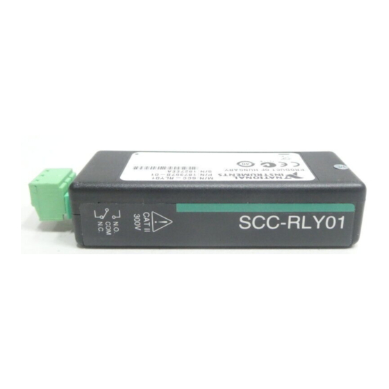
SCC-RLY01 Relay Module
Conventions
<>
»
The SCC-RLY01 contains one single-pole double-throw (SPDT)
nonlatching relay capable of switching 5 A at 30 VDC or 250 VAC.
Any single E Series DAQ device digital input/output (P0.) line 0 to 7
can control the SCC-RLY01.
The SCC-RLY01 uses positive logic. A digital high sets the relay, and
a digital low resets it. In the set state, the common (COM) contact is
connected to the normally open (NO) contact. In the reset state, the
common (COM) contact is connected to the normally closed (NC) contact.
The following conventions are used in this guide:
Angle brackets that contain numbers separated by an ellipsis represent
a range of values associated with a bit or signal name—for example,
P0.<3..0>.
The » symbol leads you through nested menu items and dialog box options
to a final action. The sequence File»Page Setup»Options directs you to
pull down the File menu, select the Page Setup item, and select Options
from the last dialog box.
This icon denotes a note, which alerts you to important information.
This icon denotes a caution, which advises you of precautions to take to
avoid injury, data loss, or a system crash. When this symbol is marked on
the product, refer to the Read Me First: Safety and Radio-Frequency
Interference document, shipped with the product, for precautions to take.
When symbol is marked on a product, it denotes a warning advising you to
take precautions to avoid electrical shock.
When symbol is marked on a product, it denotes a component that may be
hot. Touching this component may result in bodily injury.
Advertisement
Table of Contents

Related Manuals for National Instruments SCC-RLY01


Summary of Contents for National Instruments SCC-RLY01
- Page 1 Any single E Series DAQ device digital input/output (P0.) line 0 to 7 can control the SCC-RLY01. The SCC-RLY01 uses positive logic. A digital high sets the relay, and a digital low resets it. In the set state, the common (COM) contact is connected to the normally open (NO) contact.
- Page 2 SC-2345 refers to both the SC-2345 connector block and SC-2345 with configurable connectors. SCC refers to any SCC Series signal-conditioning module. What You Need to Get Started To set up and use the SCC-RLY01, you need the following items: ❑ SC-2345/2350 with one of the following: –...
- Page 3 Refer to the Read Me First: Safety and Radio-Frequency Interference document Caution before removing equipment covers or connecting/disconnecting any signal wires. Plug the SCC-RLY01 into any P0. socket J(X+9), where X is 0 to 7, on the SC-2345. Connecting the Input Signals The signal names have changed.
- Page 4 +5 V 390 Ω, 1/4 W PO ( X ) D GND For information about how to configure the SCC-RLY01 module with NI-DAQmx, refer to the SCC Quick Start Guide. Specifications These ratings are typical at 25 °C unless otherwise stated.
- Page 5 Humidity ..........10 to 90% RH, noncondensing Maximum altitude ........2,000 m Pollution Degree (indoor use only) ..2 Safety The SCC-RLY01 meets the requirements of the following standards for safety of electrical equipment for measurement, control, and laboratory use: •...
- Page 6 Refer to the Declaration of Conformity (DoC) for this product for any additional regulatory compliance information. To obtain the DoC for this product, visit , search by model number or product line, and click the ni.com/hardref.nsf appropriate link in the Certification column. SCC-RLY01 Relay Module User Guide ni.com...
- Page 7 Pin 19 5 Pin 20 Figure 1. SCC Module Bottom View Table 1 lists the signal connection corresponding to each pin. GND is the reference for the +5 V supply. Table 1. SCC-RLY01 Pin Signal Connections Pin Number Signal — —...
- Page 8 *371079B-01* Corporation. Product and company names mentioned herein are trademarks or trade names of their respective companies. For patents covering National Instruments products, refer to the appropriate location: Help»Patents in your software, the patents.txt file on your CD, or ni.com/patents.
Need help?
Do you have a question about the SCC-RLY01 and is the answer not in the manual?
Questions and answers