Texas Instruments MSP432P401R Quick Start Manual
Hide thumbs
Also See for MSP432P401R:
- User manual (41 pages) ,
- User manual (48 pages) ,
- Manual (198 pages)
Advertisement
MSP432P401R Launchpad External Target Mod
This guide walks through the steps of connecting to and programming an external target using
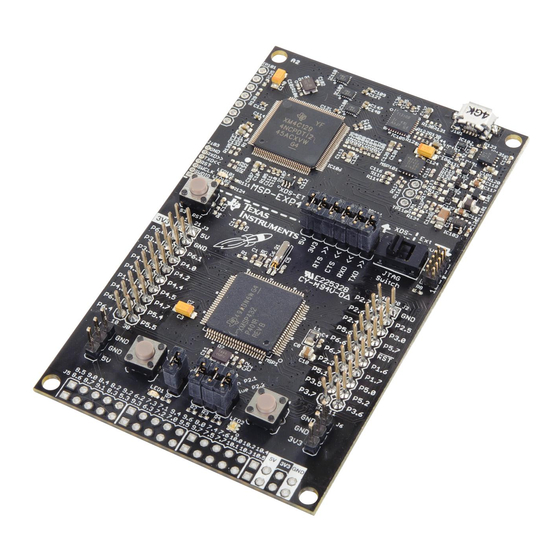
the MSP432P401R LaunchPad Development Kit.
Figure 1: MSP432P401R LaunchPad Development Kit
Step 1:
Remove the board from the packaging.
Figure 2: MSP432P401R LaunchPad out of box (with wires attached)
Advertisement
Table of Contents

Subscribe to Our Youtube Channel
Related Manuals for Texas Instruments MSP432P401R


Summary of Contents for Texas Instruments MSP432P401R
- Page 1 This guide walks through the steps of connecting to and programming an external target using the MSP432P401R LaunchPad Development Kit. Figure 1: MSP432P401R LaunchPad Development Kit Step 1: Remove the board from the packaging. Figure 2: MSP432P401R LaunchPad out of box (with wires attached)
- Page 2 Step 2: Remove the jumpers from the isolation header as well as switch S101 to the “XDS-ET” position (not the “Ext Debug” position). Figure 3: Headers Removed and Switch Positioned Step 3: Attach wires to each of the positions in J103 on the side of the board near the reset button. Figure 4: Jumper wires soldered into J103 on the LaunchPad...
- Page 3 Step 4: Attach a wire for the “TDI” signal by soldering a wire into pin 6 of the debug select switch (S101) as shown in the figure below. Ensure that the switch remains in the “XDS-ET” position. Figure 5: Wire Soldered to "TDI" Signal on S101 Step 5: Attach a wire for the “SWO”...
- Page 4 Carefully scratch off the soldermask from the trace leading to pin 12 on IC111. This will allow for more space to solder a wire. Figure 7: Close-up of IC111 and the Soldering Location for the "SWO" Signal Solder a wire to the exposed copper of the trace and be careful to not strain the wire as it may damage the board.
- Page 5 Attach the “TDI” and “SWO” wires to their corresponding positions on the target board. Step 8: Connect the MSP432P401R LaunchPad to the computer via the micro USB cable and check to see if “LED102” is illuminated green near the reset button. If the LED is not on, try cycling the power on the target board by quickly removing and replacing the +3.3V wire.
Need help?
Do you have a question about the MSP432P401R and is the answer not in the manual?
Questions and answers