
Related Manuals for Trane LIFT 162-P-1204-P


Summary of Contents for Trane LIFT 162-P-1204-P
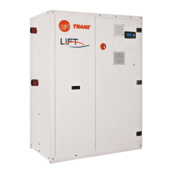
- Page 1 Installation Operation Maintenance LIFT™ 162-P-1204-P Water-cooled heat pumps with scroll compressors For hot water production at very high temperatures Heating capacity 77-550 KW November 2021 CG-SVX056A-GB...
-
Page 2: Table Of Contents
GENERAL MAINTENANCE PRELIMINARY PRECAUTIONS MAINTENANCE DOCUMENT INFORMATION WEEKLY CHECKS RANGE MONTHLY CHECKS ACCESSORIES ANNUAL CHECKS COMPLIANCE WATER CIRCUIT MACHINE IDENTIFICATION REFRIGERANT CIRCUIT INTENDED USE DECOMMISSIONING AND DISPOSING GENERAL PRECAUTIONS BASIC SAFETY RULES 1.10 RESIDUAL RISK 1.11 USER GUIDELINES 1.12 MACHINE DESCRIPTION SHIPMENT INSPECTION ON RECEIPT POSITION OF THE EQUIPMENT... -
Page 3: General
1. General Preliminary precautions Document information Range Accessories Compliance Machine identification Intended use General precautions Basic safety rules 1.10 Residual risk 1.11 User guidelines 1.12 Machine description 1.1 Preliminary precautions These units must be installed by a qualified company that at the end of the work provides the operator with a declaration of conformity with the regulations in force and the instructions provided by in this document. -
Page 4: Range
1.2.1 Symbols • This publication contains the following symbols: Draws attention to actions that can cause serious injury if not performed Danger correctly. Prohibited Draws attention to actions that impose a prohibition. 1.3 Range LIFT Frame feature plate 1.3.1 Available versions Electrical board feature plate LIFT Heat Pump... -
Page 5: General Precautions
1.8 General precautions The guidelines for the prevention of accidents reported below, with reference to the relative areas of residual risk, must be integrated with all the general instructions of this chapter and with the • If the refrigerant should leak, ventilate the room. The liquid refrigerant produces toxic gas accident prevention regulations in force in the destination country of the system. -
Page 6: User Guidelines
1.12 Machine description Measures to be adopted if refrigerant gas leaks: - R134a 1.12.1 Features First aid measures Frame. • General information: Self-supporting galvanized steel frame further protected with polyester powder painting. Easy to - do not administer anything to an unconscious person. remove panels allow access to the inside of the unit for maintenance and other necessary •... -
Page 7: Shipment
2. Shipment Inspection on receipt Position of the equipment Equipment Storage Handling Unpacking Access to internal parts Resting on the ground 2.1 Inspection on receipt Packaging plate Keep the documentation in a dry place to prevent deterioration, for at least 10 years for future reference. -
Page 8: Unpacking
Do not exceed the maximum inclination allowed, as shown in the figure. • Insert the forks from the side to avoid damaging the panels. • Before placing the machine on the ground remove the wooden supports. 2.6 Unpacking 2.5.2 Lifting with a crane Wooden support Bar for lifting (maximum ø... -
Page 9: Resting On The Ground
• Unscrew the fixing screws and remove the panels. To access the electrical board: • Remove the panels of the electrical board. • Set the disconnecting switch knob to Off. • Open the doors of the electrical board. 2.8 Resting on the ground The unit must be positioned on a perfectly horizontal surface that is able to withstand its weight. -
Page 10: Installation
3. Installation Installation location requirements Operating limits Unit location Verifying clearances (clearance area) 3.1 Installation location requirements The installation place must be chosen as specified in standard EN 378-1 and the requirements of standard EN 378-3. In any case, the installation site must consider the risks associated with an accidental leak of refrigerant gas contained in the direct expansion units. -
Page 11: Verifying Clearances (Clearance Area)
Place a rigid rubber band between the base of the machine and the support surface. Verify that the support surface withstands the weight of the unit. Provide a supporting slab of proportional dimensions with the unit if resting on unstable ground. -
Page 12: Water Connections
4. Water connections Connection diagram Position of connections Hydraulic data Connection to the system PV3E evaporation control PV3C cold start 4.1 Connection diagram 4.3 Hydraulic data Unit 4.3.1 Water volume Anti-vibration joint (recommended) Check valve The machine electronic control, to protect the electrical motor, limits hourly start up of the Flow switch (mandatory) compressor. -
Page 13: Connection To The System
Content Concentration mg/l or ppm Material <10 Electrical conductivity μS/cm 10-500 >500 <2 Ammonium 2-20 >20 <1 Free chlorine >5 <0.05 Hydrogen Sulphide >0.05 <5 Free Carbon Dioxide 5-20 >20 In these models, the connections are positioned outside the unit. <100 Nitrate •... -
Page 14: Pv3C Cold Start
In Input In Input Out Output Out Output ST3 Temperature probe ST1 Temperature probe ST4 Temperature probe ST2 Temperature probe SFA Air vent valve SFA Air vent valve RSA Water drain valve RSA Water drain valve PW Differential pressure switch PW Differential pressure switch CA Condenser CA Condenser... -
Page 15: Electrical Connections
5. Electrical connections Machine connection Connections of the accessories 5.1 Machine connection • Set the main switch to 0. • Turn the two fixing screws 1/4 of a turn and open the board doors. Pre-cut-out for side entry • Use the hole for the main power cable and the hole for the cables of other external connections. -
Page 16: Commissioning
6. Commissioning Preliminary inspections First start-up or restart after long inactivity Shut-down Flow rate calibration 6.1 Preliminary inspections - Read the temperature indicated on the pressure gauge connected to the inlet. - The difference between these temperatures provides the overheating value. •... -
Page 17: Flow Rate Calibration
6.3.2 Shut-down for long periods Not using the unit for a long period of time requires the following operations to be performed: • Disable the unit in any mode of operation it may be, from the control panel. • Set the remote switch to "OFF" (if present) after having turned off the unit. •... -
Page 18: Control Panel
7. Control Panel User interface Switch on and off Settings Unit Status Alarms Login Software Electric control information 7.1 User interface 7.1.1 Control panel Indicates the Set-Point temperature. Alarm The control panel enables all machine functions to be performed, to display its operation and any alarms which may be triggered. - Page 19 Indicate pumps operation. The flowing message can indicate some unit operations or alarms. Unit power 7.1.3 Function keys UP Function It indicates the actual power quantity of the unit: P1 power circuit 1; P2 power circuit 2. Cooling By using the UP key it is possible to move upwards between the parameters and increase a value. The extended pressure of UP button allows to turn on or off the unit.
-
Page 20: Switch On And Off
Press the ENTER key to confirm. The unit can be switched on or off directly from the main screen: pushing the UP key for 5 seconds the unit switches from on to off and vice versa. By using the LEFT key it is possible to move to the left within the parameters. ESC Function If the machine is switched off, the display will show the sign OFF. - Page 21 Press the ENTER key. Press the ESC key to exit. All software contents will appear translated in the language selected. 7.3.2 Date and time 7.3.3 Set-point The adjustment must be made while the machine is off. From control panel it is possible to set the water temperature value (outlet water). Press the ENTER key to access the main menu.
-
Page 22: Unit Status
By using the UP and DOWN keys it is possible to select the set-point to modify: SC1 summer set- In units fitted with the IAV or IAA accessory (factory fitted accessories), the set-point can be point. modified by using a remote signal. Press the ENTER key to modify the value. - Page 23 Select one of the solenoid valves. Inputs and outputs Select the Input/Output menu. Press the ENTER key. Press the ENTER key to access the Input/Output menu. Press the ENTER key to display the expansion valve status. Press the ENTER key to display the status. The operation can be repeated for both expansion valves.
-
Page 24: Alarms
Press the ENTER key to display the counters status. Press the ENTER key to access the main menu. Press the ENTER key to display the compressor counter. Select the ALARMS Status menu. Use the UP and DOWN keys to display the status of all compressors. Press the ENTER key to access the ALARMS menu. - Page 25 It is also possible to reset an alarm directly from the main screen. From the main screen, press the ESC key to display the alarm triggered. 7.5.2 Alarms reset Some alarms can be reset directly from the control panel. Press and hold the ESC key for 5 seconds. Press the ENTER key to access the main menu.
-
Page 26: Login
Edit all fields by entering the password. Press the ENTER key to display the alarms triggered history. The advanced functions menus can be accessed by entering the password. 7.7 Software It is possible to obtain information on the software installed on your machine. Press the ENTER key to access the main menu. - Page 27 Use the UP and DOWN keys to select the DEVICE INFO menu. Press the ENTER key. From this screen you can view the information of the machine on which the software is installed.
-
Page 28: Maintenance
8. Maintenance Maintenance Weekly checks Monthly checks Annual checks Water circuit Refrigerant circuit Decommissioning and disposing 8.1 Maintenance • Verify that the following safety devices work properly: - High pressure switch; Regular maintenance is essential to maintain the efficiency of the unit in terms of operation and - Low pressure switch;... -
Page 29: Refrigerant Circuit
It is advisable to repeat this operation after the unit has been operating for a few hours and regularly check the system pressure. Top-ups must be carried out with the machine off (pump OFF). The system must be filled to a pressure range between 1 and 2 bar. 8.5.2 Draining of the water circuit •... - Page 30 Trane - by Trane Technologies (NYSE: TT), a global climate innovator - creates comfortable, energy efficient indoor environments for commercial and residential applications. For more information, please visit trane.eu or tranetechnologies.com. Trane has a policy of continuous product and product data improvement and reserves the right to change design and specifications without notice. CG-SVX056A-GB_1121...
Need help?
Do you have a question about the LIFT 162-P-1204-P and is the answer not in the manual?
Questions and answers