Table of Contents
Advertisement
ALL phases of this installation must comply with NATIONAL, STATE AND LOCAL CODES
Important — This Document is customer property. Please return to service information pack and give this Installer's Guide to the homeowner
upon completion of work.
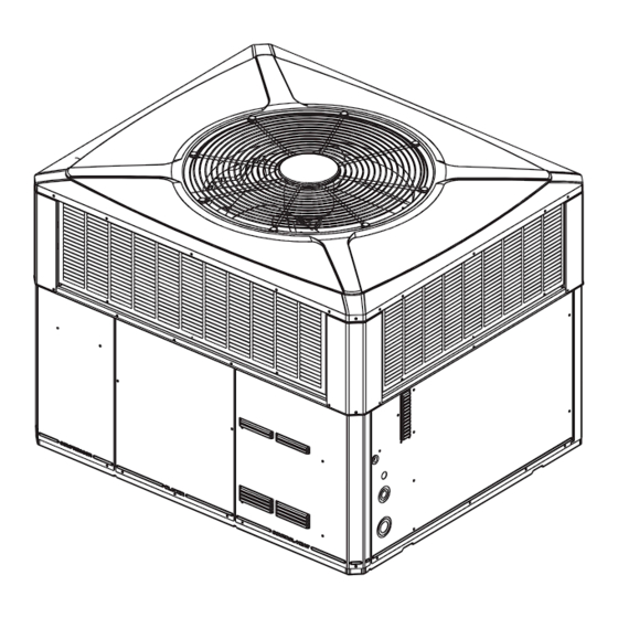
4WCC3018 through 4WCC3060
WARNING:
Installer's Guide
Single Packaged Heat Pump, 13 SEER
Convertible,
HAZARDOUS VOLTAGE - DISCONNECT POWER and DISCHARGE
1½
- 5 Ton, R-410A
4WCX3018 through 4WCX3060
CAPACITORS BEFORE SERVICING
18-EB24D1-19
WCC-IG-19
Advertisement
Table of Contents

Related Manuals for Trane 18-EB24D1-19


Summary of Contents for Trane 18-EB24D1-19
- Page 1 18-EB24D1-19 Installer's Guide WCC-IG-19 Single Packaged Heat Pump, 13 SEER Convertible, 1½ - 5 Ton, R-410A ALL phases of this installation must comply with NATIONAL, STATE AND LOCAL CODES Important — This Document is customer property. Please return to service information pack and give this Installer's Guide to the homeowner upon completion of work.
-
Page 2: Safety Considerations
Installer’s Guide Safety Considerations IMPORTANT: Read this entire manual before beginning installation procedures. Read this manual carefully before attempting to install, operate, CAUTION ▲ or perform maintenance on this unit. Installation and maintenance should be performed by qualified service technicians only. CONTAINS REFRIGERANT! SYSTEM CONTAINS OIL AND REFRIGERANT UNDER NOTE: "Warnings"... -
Page 3: Table Of Contents
Installer’s Guide Contents Introduction Safety Considerations Read this manual carefully before attempting to install, oper- Introduction ate, or perform maintenance on this unit. Installation and Step 1-Inspect Shipment maintenance should be performed by qualified service techni- Step 2-Determine Unit Clearances cians only. -
Page 4: Step 2-Determine Unit Clearances
Installer’s Guide Step 2—Determine Unit Clearances Figures 1 through 12 show the unit critical dimensions. Fig- ures 1 through 6 show the 4WCC3 clearances and Figures 7 through 12 show the 4WCX3 clearances. NOTE: The view labeled “Bottom Side” represents the Base as viewed looking up from underneath the unit. - Page 5 Installer’s Guide Figure 2. 4WCC3018 through 4WCC3036 (2 of 3) Page 5...
- Page 6 Installer’s Guide Figure 3. 4WCC3018 through 4WCC3036 (3 of 3) Page 6...
- Page 7 Installer’s Guide NOTE: The view labeled “Bottom Side” represents the Base as viewed looking up from underneath the unit. Figure 4. 4WCC3042 through 4WCC3060 (1 of 3) Page 7...
- Page 8 Installer’s Guide Figure 5. 4WCC3042 through 4WCC3060 (2 of 3) Page 8...
- Page 9 Installer’s Guide Figure 6. 4WCC3042 through 4WCC3060 (3 of 3) Page 9...
- Page 10 Installer’s Guide NOTE: The view labeled “Bottom Side” represents the Base as viewed looking up from underneath the unit. Figure 7. 4WCX3018 through 4WCX3036 (1 of 3) Page 10...
- Page 11 Installer’s Guide Figure 8. 4WCX3018 through 2/4WCX3036 (2 of 3) Page 11...
- Page 12 Installer’s Guide Figure 9. 4WCX3018 through 4WCX3036 (3 of 3) Page 12...
- Page 13 Installer’s Guide NOTE: The view labeled “Bottom Side” represents the Base as viewed looking up from underneath the unit. Figure 10. 4WCX3042 through 4WCX3060 (1 of 3) Page 13...
- Page 14 Installer’s Guide Figure 11. 4WCX3042 through 4WCX3060 (2 of 3) Page 14...
- Page 15 Installer’s Guide Figure 12. 4WCX3042 through 4WCX3060 (3 of 3) Page 15...
-
Page 16: Step 3-Review Location & Recommendation Information
Installer’s Guide Step 3—Review Location and Recommendation Information CAUTION Down Airflow Units ▲ Location of the unit must allow service clearance around it to Caution must be taken at all times to avoid personal injuries ensure adequate serviceability, maximum capacity, and peak and/or damage to equipment. -
Page 17: Step 4-Unit Installation
Installer’s Guide Step 4—Unit Installation NOTE: The factory ships this unit for horizontal installation. Rooftop Installation -- Curb Mounting Ground Level Installation Convert Horizontal Airflow to Down Airflow To install the unit at ground level: The factory ships the unit for horizontal airflow. Perform this 1. -
Page 18: Lifting And Rigging
Installer’s Guide Figure 14. Converting Horizontal to Down Airflow Lifting and Rigging Placing the Unit on the Mounting Curb 1. The unit is designed with a perimeter drip lip that is lower than IMPORTANT: Do not lift the unit without test lifting for balance the unit base pan, see Figure 16, inset A, on page 20. -
Page 19: Rooftop Installation -- Frame Mounting
Installer’s Guide Small Cabinet Medium Cabinet *****018-036 *****042-060 NOTE: These views represent the base as viewed looking up from underneath the unit. IMPORTANT: Unit requires vibration isolator support in the general areas shown. Locate 3/4" thick vibration isolators on the bottom of the basepan as illustrated by black dots for ground level pad applications. - Page 20 Installer’s Guide IMPORTANT: To prevent damage to the sides and top of the unit when hoisting, retain the top shipping skid Base of unit on the unit or use “spreader bars” as Drip lip on rest on top of perimeter of shown in these illustrations.
- Page 21 Installer’s Guide Supply Air Return Air Roof Flashing Channel Iron Center Support (Center Sup- port required on all Frame Applications.) Angle Iron Frame Figure 18. Typical Rooftop Horizontal Airflow Application with Frame Supply Air Return Air Roof Flashing Roof Flashing Angle Iron Frame Channel Iron Center Support (Center Support required on all...
-
Page 22: Ductwork Installation
Installer’s Guide Ductwork Installation Attaching Downflow Ductwork to Roof Curb UNIT EXTERIOR Supply and return air flanges are provided on the roof curb for easy WEATHERPROOF duct installation. All ductwork must be run and attached to the curb THIS SEAM FIELD DUCT before the unit is set into place. -
Page 23: Electrical Wiring
Installer’s Guide Table 1. Filter Sizes (field supplied filter rack) FILTER SIZE FILTER RESISTANCE UNIT NOMINAL CFM (Sq Ft) ("W.C.) WC~3018 2.00 0.08 WC~3024 2.67 0.08 WC~3030 1000 3.33 0.08 WC~3036 1200 4.00 0.08 WC~3042 1400 4.67 0.08 WC~3048 1600 5.33 0.08 WC~3060... -
Page 24: Field Wiring Diagram
Installer’s Guide NOTES: 1. FUSED DISCONNECT SIZE, POWER WIRING AND GROUNDING OF EQUIPMENT MUST COMPLY WITH CODES. UNIT HEATER AREA UNIT CONTROL BOX 2. BE SURE POWER SUPPLY AGREES WITH EQUIP- MENT AND HEATER NAMEPLATE. 3. LOW VOLTAGE WIRING TO BE 18 AWG MINIMUM CONDUCTOR. -
Page 25: Control Wiring (Class Ii)
Installer’s Guide Do the condenser fan and indoor blower turn free without Control Wiring (Class II) rubbing, and are they tight on the shafts? Low voltage control wiring should not be run in conduit with power Has all work been done in accordance with applicable local wiring unless Class 1 wire of proper voltage rating is used. -
Page 26: Starting The Unit In Heating Mode
Installer’s Guide and outdoor fan motor. The indoor thermostat contact TSH-1 also Starting the Unit in Heating Mode provides power to “G” ter minal on the indoor thermostat energizing NOTE: See the section on Sequence of Operation for a descrip- the fan relay (F), which starts the indoor fan motor. -
Page 27: Final Installation Checklist
Installer’s Guide Final Installation Checklist Service Maintenance Cooling Season Does the unit run and operate as described in the section on Sequence of Operation, page 26, in response to the room To keep the unit operating safely and efficiently, the manufacturer thermostat? recommends that a qualified service technician check the entire system at least once each year or sooner if needed. -
Page 28: Service Information
Be sure the thermostat is properly set. Service Phone_________________________________________________________________ Trane The manufacturer has a policy of continuous product and product data improvement. It reserves the right to change design and specification without notice. 6200 Troup Highway Tyler, TX 75707-9010 © 2014 Trane 04/14 Page 28...
Need help?
Do you have a question about the 18-EB24D1-19 and is the answer not in the manual?
Questions and answers