Table of Contents
Advertisement
Quick Links
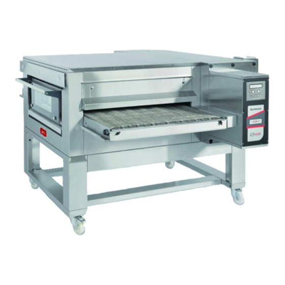
SYNTHESIS
12/80V E
ATTENZIONE:
Leggere le istruzioni prima di utilizzare l'apparecchio
WARNING:
Read instructions before using the equipment
ATENCIÓN:
Leer bien las instrucciones antes de usar la máquina
ATTENTION:
Lire les instructions avant d'utiliser l'appareil
ACHTUNG:
Vor der Benutzung des Gerätes die Anweisungen lesen.
Manuale di installazione, uso e manutenzione
Manual for installation, use and maintenance
Manual de instalación, uso y manutención
Notice d'installation, d'utilisation et d'entretien
I
-, B
-
I
NSTALLATIONS
EDIENUNGS
UND
NSTANDHALTUNGSHANDBUCH
Advertisement
Table of Contents

Related Manuals for ZANOLLI SYNTHESIS 12/80V E


Summary of Contents for ZANOLLI SYNTHESIS 12/80V E
- Page 1 SYNTHESIS 12/80V E ATTENZIONE: Leggere le istruzioni prima di utilizzare l’apparecchio WARNING: Read instructions before using the equipment ATENCIÓN: Leer bien las instrucciones antes de usar la máquina ATTENTION: Lire les instructions avant d’utiliser l’appareil ACHTUNG: Vor der Benutzung des Gerätes die Anweisungen lesen. Manuale di installazione, uso e manutenzione Manual for installation, use and maintenance Manual de instalación, uso y manutención...
- Page 2 TRADUCCION DE INSTRUCCIONES ORIGINALES TRADUIT DES INSTRUCTIONS ORIGINALES UBERSETZT AUS DER ORIGINALBETRIEBSANLEITUNG SYNTHESIS 12/80V E L’alimentazione del forno deve essere collegata ad un quadro elettrico dotato di sezionamento dei poli. The oven supply must be connected to an electrical panel with all poles sectioning.
-
Page 3: Table Of Contents
IDEX INDEX 1. INTRODUCTION ................... 5 2. HOW TO USE THIS MANUAL .............. 6 3. TECHNICAL SPECIFICATIONS ............8 3.1. Identifying the product ............... 8 3.2. Directives compliance ..............8 3.3. Foreseen range of use ..............8 3.4. Technical Specifications ............8 4. - Page 4 IDEX 7.1.1. Warnings for installers ............25 7.1.2. Warnings for users .............. 25 7.1.3. Warnings for the maintenance operator ....... 26 8. CLEANING ..................27 8.1. Cleaning removable parts ............27 8.2. Cleaning of external parts ............28 8.3. Cleaning the baking chambers ..........28 9.
-
Page 5: Introduction
1. INTRODUCTION 1. INTRODUCTION The electric conveyor ovens mod. SYNTHESIS have been designed mainly for the automatic cooking of pizza and similar products. They are conveyor ovens. Favourable peculiarity of these particular ovens is that it is possible to make excellent baking, without controlling the same. For this reason it is possible for un unqualified staff to use the oven. -
Page 6: How To Use This Manual
If this copy is lost, destroyed and/or a digital copy is required, it can be requested via email at zanolli@zanolli.it quoting the machine’s registration number and model. This manual is made up of a number of chapters. They should be... - Page 7 2. HOW TO USE THIS MANUAL Chapters 5, 6 and 7 are intended for the user who has to learn how to use the machine. These serve as a guide to the essential operations of turning on, using and turning off of the machine under safe conditions. Chapter 8 gives all the information necessary for the cleaning of the equipment: all those operations that must be carried out by the user to guarantee that it continues to function under safe, hygienic and sanitary...
-
Page 8: Technical Specifications
3. TECHNICAL SPECIFICATIONS 3. TECHNICAL SPECIFICATIONS 3.1. Identifying the product This manual refers to conveyor oven SYNTHESIS E. 3.2. Directives compliance The oven SYNTHESIS carry the obligatory mark, that guaranteeing their conforming to the following European directives: 2014/35/CE low current directive; 2014/30/CE electromagnetic compatibility directive;... -
Page 9: Installation
4. INSTALLATION 4. INSTALLATION ATTENTION! These installation instructions are for the exclusive use of personnel qualified for the installation and maintenance of electrical equipment conceived for professional use in the foodservice industry and community catering operations. An installation carried out by unqualified persons could cause damage to the machine, to people, animals or property ATTENTION! Proceed with the installation according to those norms in force in the country where it is being carried out. -
Page 10: Moving The Unit
4. INSTALLATION Install the appliance in a dry and easily accessible place both to facilitate its use and to carry out cleaning and maintenance. The appliance must be installed at least 20 cm from the walls of the room or from other equipment so that the ventilation outlets located on the sides of the oven are not obstructed. -
Page 11: Positionig The Unit On Its Base
4. INSTALLATION 4.4. Positionig the unit on its base Position the oven by sliding it into the four corners of the basement (Fig.2). 4.5. Positioning stacked units FOR THE UNITS THAT CAN BE STACKED ONE ON TOP OF THE OTHER SEE ENCLOSURE B. Once the first oven has been positioned on the base (see previous... -
Page 12: Exhaust Produced By Combustion
4. INSTALLATION The figure below shows the position of the equipotential bonding terminal on the oven and its symbol: The coupling between plug and socket must be such that the earth conductor is connected first and disconnected last and must have the right dimensions for the rated current (see Enclosure A). -
Page 13: Checking Before Starting Work
4. INSTALLATION The Manufacturer cannot answer for damage caused by ignoring these abovementioned norms as well as the information in this manual. 4.8. Checking before starting work After completing installation of the unit a series of checks must be carried out, listed as follows: check that the various disassembled parts have been assembled. -
Page 14: Operation
5. OPERATION 5. OPERATION 5.1. Control panel Oven on-off key Parameter value decrease key Programme access key Parameter value increase key Conveyor start/stop key Automatic switching on-off key Economy function key Cooking program setting key. SYNTHESIS E... -
Page 15: Functional States Of The System
5. OPERATION 5.2. Functional states of the system 5.2.1. Inactive state In the inactive state (Fig.1-2) the circuit board is supplied with current but all the oven’s functions are disabled, apart from those for programming. The display indicates “OFF”, the current time, the day and time the oven will next be automatically switched on (if it set, Fig.2). -
Page 16: Settings
5. OPERATION 5.3. Settings 5.3.1. Setting the current time The current time can be set by the user both when the oven is only off. Press the key for 3 consecutive seconds to enter the setting mode (Fig.4). The display indicates (Fig.4), where: A = current day B = current month C = current year... -
Page 17: Programming
5. OPERATION 5.4. Programming 5.4.1. Cooking programs It is possible to manage up to 6 different cooking programs. Each can be set in the following order: 1. Cooking time (minutes : seconds) 2. Temperature setting (°C). 3. Top heating element power percentage 4. -
Page 18: Cooking Time Adjustment
5. OPERATION 5.4.2. Cooking time adjustment The desired cooking time is set directly by the user, and is directly connected to the relevant conveyor speed, which is automatically controlled by the electronic circuit board. When the oven is switched on, the conveyor is still and the cooking time flashes on the display. - Page 19 5. OPERATION On the display you can read the percentage of ignition of the heating elements (B = top heating elements %, C = bottom heating elements %). When the heating elements are switched on, on the display the indicator A for the top and D for the bottom is shown.
-
Page 20: Economy Fuction
5. OPERATION 5.4.5. Economy Fuction The Economy function allows the oven, when left idle, to be kept at a lower temperature than that when it is in use. This saves energy and consequently money. Apart from managing the temperature of the oven this can determine whether the wire mesh conveyer moves or not. -
Page 21: Programming Switching On
5. OPERATION 5.4.6. Programming switching on enter setting mode programmed switching press immediately release the key enable/disable auto power (Fig.18) with the oven on or off. At first the state of the automatic switching on (active or inactive) appears on the display (AUTOSTART : ON or OFF). -
Page 22: Alarms
5. OPERATION To indicate that the ignition has been enabled, in the idle state the display shows the date and time of the next time (Fig.22). ). If the ignition is turned off, instead of the day and time the message appears "OFF". 5.5. -
Page 23: Over
5. OPERATION The oven continues working and only probe 1 is used to measure the temperature. The control temperature is automatically raised by 40°C. This variation in the temperature value is effected to correct the only value taken in the coldest part of the oven and to simulate a value near to the real one previously elaborated by making the average between the hottest and coldest points. -
Page 24: Preparation For Use And Before Turning
6. USE 6. USE During cooking or at the end of cooking some of the oven's surfaces reach dangerous temperatures. The symbol warns of this danger. Never touch these surfaces and only use the proper handle. 6.1. Preparation for use and before turning If the unit has just been installed or if it has not been used for several days before using it to work you need to clean it completely food as described in Chapter cleaning, to eliminate manufacturing waste,... -
Page 25: Safety Warnings
7. SAFETY WARNINGS 7. SAFETY WARNINGS 7.1. Prohibited actions and obligations towards the prevention of accidents Read the warnings listed in this chapter carefully. They give important indications concerning safety. It is forbidden to install accessories that do not conform with safety standards. -
Page 26: Warnings For The Maintenance Operator
7. SAFETY WARNINGS - keep the safety systems in good working order; - carry out all working procedures with the utmost safety and calm; - use protective thermal gloves or pliers to raise or lower the oven doors, avoiding direct contact with the hands; - respect the instructions and warnings highlighted by the signs on the equipment. -
Page 27: Cleaning
8. CLEANING 8. CLEANING Cleaning should be carried out with the equipment turned off room temperature having taken precaution disconnecting the electricity supply. Weekly maintenance can be carried out by the equipment’s operator given that they observe the safety procedures set out in this manual. A simple but regular and careful clearing guarantees efficient performance and the normal functioning of this equipment. -
Page 28: Cleaning Of External Parts
8. CLEANING Cleaning of the drawers of entry and exit should be performed every 4 hours of operation. 8.2. Cleaning of external parts The crystals are particularly sensitive to sudden changes in temperature that can cause them to break into tiny fragments. Do not handle the crystals and not bring them into contact with the water until they are at room temperature. -
Page 29: Maintenance
9. MAINTENANCE 9. MAINTENANCE WARNING! These use and maintenance instructions are intended only for staff qualified for the installation and maintenance of electrical equipment. Maintenance by other persons may cause damage to the equipment, persons, animals or things. In the majority of cases it is necessary to remove the fixed guards in order to carry out repairs and checks. -
Page 30: Replace Battery
9. MAINTENANCE 9.3. Replace battery The alarm message “BATTERY” has to be referred to the buffer battery of the electronic base board, which is over and must be replaced. The message on the display is given together with an alarm, which intermittently sounds. -
Page 31: Routine Maintenance
9. MAINTENANCE paragraph 5.3.1). Then disconnect the oven from the main power and connect it again. This operation permits to reset the base board and delete any other alarms in memory. 9.4. Routine maintenance Below we provide a series of instructions for the routine inspection and maintenance of the equipment, to be carried out periodically depending on the use and the state of cleanliness of the oven. - Page 32 9. MAINTENANCE - that the fixing screws of the electrical power connections of all the contactors and the electrical terminals are not loose. Tighten them if necessary; - The wear of the carbon brushes of the rack gearmotor; - The operation/cleanliness of the cooling fans; - In the area of the fan motor, check and clean the motors;...
-
Page 33: Decomissioning And Demolition
10. DECOMISSIONING AND DEMOLITION 10. DECOMISSIONING AND DEMOLITION Before proceeding with the decommissioning disconnect the electrical supplies to the equipment and any other connections there may be and then move the modules using suitable means such as: forklift trucks, hoists, and so on. -
Page 35: Technical Enclosures
SYNTHESIS 12/80 VE Allegati tecnici Technical enclosures Anexos técnicos Fichiers techniques joints ECHNISCHE NLAGEN... -
Page 36: Technical Specifications
A. Caratteristiche tecniche Synthesis 12/80 VE A. Technical specifications Synthesis 12/80 VE A. Especificaciones técnicas Synthesis 12/80 VE ENGLISH ESPAÑOL ITALIANO Weight Peso 330 kg Peso Dimensioni esterne Overall dimensions Dimensiones externas 1645x2180x595 mm (AxBxC) (AxBxC) (AxBxC) Larghezza rete (D) Conveyor width (D) Amplitud red (D) 800 mm... - Page 37 A. Spécifications techniques Synthesis 12/80 VE A. T 12/80 VE ECHNISCHE SPEZIFIKATIONEN YNTHESIS DEUTSCH FRANÇAIS 330 kg Poids EWICHT Dimensions ext. (AxBxC) 1645x2180x595 mm UßENABMESSUNGEN Largeur ruban transp. (D) 800 mm ETZBANDBREITE Longueur ruban transp. (E) 2100 mm ETZBANDLÄNGE 1200 mm Longueur chambre (F) ACKKAMMERLÄNGE 49-56 (150/170 pizzas/h...
- Page 38 B. Allacciamenti alimentazione elettrica, per un modulo di cottura e per la sovrapposizione di massimo tre moduli di cottura B. Connections for electrical for a single cooking unit and a maximum of three cooking units stacked one on top of another B.
-
Page 39: Wiring Diagrams
C.1. Schema elettrico Synthesis 12/80 VE (400 Vac. ~ 3+N 50-60Hz) C.2. Collegamento dei motori in 60Hz C.3. Variante collegamento potenza Synthesis 12/80 VE (230 Vac. ~ 3 50-60Hz) C.1. Wiring diagram Synthesis 12/80 VE (400 Vac. ~ 1+N 50-60Hz) C.2. - Page 40 C.1. IMPI0192 SYNTHESIS 12/80 VE...
- Page 41 C.2. SYNTHESIS 12/80 VE...
- Page 42 C.3. IMPI0192-3 SYNTHESIS 12/80 VE...
-
Page 43: Exploded Views And List Of Spare Parts
D. DISEGNI ESPLOSI ED ELENCO PARTI DI RICAMBIO Per interventi complessi e nel caso di rotture vi preghiamo di contattarci. Comunque, allo scopo di semplificare la ricerca dei guasti e l’eventuale sostituzione delle parti danneggiate, diamo di seguito una lista delle parti di ricambio, i disegni esplosi e figure con i riferimenti a ciascuna delle parti elencate. - Page 44 Tabella codici di riferimento componenti di carpenteria List of spare component parts Tabla códigos de referencia componentes de carpintería DESCRIPTION DENOMINACIÓN DESCRIZIONE Telaio vetro esterno Door external glass frame Telar vidrio externo puerta CARP1909 porta Maniglia porta Door handle Manilla puerta MANI0057 Giunto supporto vetro Coupling for external glass...
- Page 45 Table codes de référence composants de charpenterie ETALLBESTANDTEILE ODENTABELLE BESCHREIBUNG DÉSIGNATION Structure vitre externe porte CARP1909 UßENGLASRAHMEN ÜR Poignée porte MANI0057 ÜRGRIFF Joint support vitre externe CARP1870 ERBINDUNGSSTÜCK UßENGLASSCHEIBE Ressort gauche SPRI0009 INKE EDER BOCC0006 Raccord porte ÜRBÜCHSE Structure porte PORT0507 ÜRRAHMEN Porte interne...
- Page 46 SYNTHESIS 12/80 VE...
- Page 47 SYNTHESIS 12/80 VE...
- Page 48 Tabella codici di riferimento componenti elettrici List of electrical components parts Tabla códigos de referencia componentes eléctricos DESCRIZIONE DESCRIPTION DENOMINACIÓN Scheda display Display Card Cédula display ELET0673 Motore rete (Transtecno) Conveyor motor (Transtecno) Motor red (Transtecno) MOTO0052 Motore rete (Automec) Conveyor motor (Automec) Motor red (Automec) MOTO0004...
- Page 49 Tableau des codes de référence composants électriques ABELLE BEZUGSARTIKELNUMMERN ELEKTRISCHEN OMPONENTE BESCHREIBUNG DÉSIGNATION Carte display ELET0673 ISPLAYKARTE Moteur ruban transporteur (Transtecno) MOTO0052 ETZBANDMOTOR RANSTECNO Moteur ruban transporteur MOTO0004 ETZBANDMOTOR UTOMEC (Automec) ELET0676 Carte base RUNDELEKTRONIKKARTE Transformateur toroïdal pour carte INGKERNTRANSFORMATOR FÜR ELET0156 base ASISKARTE...
- Page 50 SYNTHESIS 12/80 VE...
- Page 51 SYNTHESIS 12/80 VE...
- Page 53 SYNTHESIS / BM Manuale di installazione, uso e manutenzione Manual for installation, use and maintenance Manual de instalación, uso y manutención Notice d’installation, d’utilisation et d’entretien -, B NSTALLATIONS EDIENUNGS NSTANDHALTUNGSHANDBUCH...
- Page 54 1. IDENTIFICAZIONE DEL PRODOTTO Questo manuale si riferisce ai basamenti dei forni serie Synthesis modelli: 06/40, 08/50, 11/65, 12/80, 12/100. I basamenti dei forni sopra citati sono stati progettati per il supporto dei moduli di cottura. 1. IDENTIFYING THE PRODUCT This manual refers to bases for the ovens 06/40, 08/50, 11/65, 12/80, 12/100 models in the Synthesis series.
- Page 55 2. ISTRUZIONI DI MONTAGGIO I basamenti vengono consegnati smontati e forniti con kit bulloneria necessario al montaggio, nelle due configurazioni previste (vedi disegni esplosi): A) basamento per n°1 o 2 moduli di cottura sovrapposti B) basamento per n°3 moduli di cottura sovrapposti. Diamo di seguito i disegni esplosi e una lista delle parti che compongono i basamenti, con riferimenti a ciascuna delle parti elencate.
- Page 56 SYNTHESIS / BM...
- Page 57 ②+⑤ Traverse Gambe+carter Crosspieces Legs+cover Travesaños Pies+carter Traverses Jambes RAVERSE TÜTZBEIN ⑥ FRONT ① LAT 1 MC 2 MC 3 MC TRAV0223 TRAV0223 TRAV0224 TRAV0220 TRAV0221 SYNTHESIS 06/40 EL CART0266 CART0266 CART0267 TRAV0223 TRAV0223 TRAV0224 TRAV0220 TRAV0222 SYNTHESIS 06/40 GAS CART0266 CART0266 CART0267 TRAV0195 TRAV0195 TRAV0167...
- Page 58 Per la pulizia delle superfici esterne in acciaio inox utilizzare una spugna morbida inumidita, eventualmente con un detersivo leggero, non abrasivo. Non usare detersivi abrasivi o corrosivi, poiché renderebbero opaco l'acciaio inox. To clean the external stainless steel surfaces, use a soft sponge dampened with a weak non abrasive detergent.
- Page 59 Raccolta differenziata. Questo prodotto non deve essere smaltito con i normali rifiuti domestici. In base alle normative locali, i servizi per la raccolta differenziata possono essere disponibili presso i punti di raccolta municipali. Source separation for recycling. This product must not be disposed of together with normal domestic waste.
- Page 60 Dr. Zanolli s.r.l. Via Casa Quindici, 22 37066 Caselle di Sommacampagna VR Tel. +39-0458581500 Fax +39-0458581455 VAT N.IT00213620230...
Need help?
Do you have a question about the SYNTHESIS 12/80V E and is the answer not in the manual?
Questions and answers