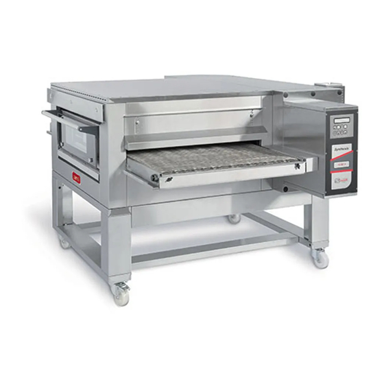
ZANOLLI SYNTHESIS 08/50 V PW GAS Manual For Installation
Hide thumbs
Also See for SYNTHESIS 08/50 V PW GAS:
- Manual for installation, use and maintenance (60 pages)
Table of Contents
Advertisement
Quick Links
08/50 V PW GAS
Manuale di installazione, uso e manutenzione
Manual for installation, use and maintenance
Manual de instalación, uso y manutención
Notice d'installation, d'utilisation et d'entretien
I
NSTALLATIONS
SYNTHESIS
-, B
EDIENUNGS
DR. ZANOLLI s.r.l.
Via Casa Quindici, 22
37066 Caselle di Sommacampagna
(Verona) Italy
Tel +39 045 8581500 (r.a.)
Fax +39 045 8581455
Web: www.zanolli.it • e-mail: zanolli@zanolli.it
-
I
UND
NSTANDHALTUNGSHANDBUCH
Advertisement
Table of Contents

Related Manuals for ZANOLLI SYNTHESIS 08/50 V PW GAS


Summary of Contents for ZANOLLI SYNTHESIS 08/50 V PW GAS
- Page 1 Via Casa Quindici, 22 37066 Caselle di Sommacampagna (Verona) Italy Tel +39 045 8581500 (r.a.) Fax +39 045 8581455 Web: www.zanolli.it • e-mail: zanolli@zanolli.it SYNTHESIS 08/50 V PW GAS Manuale di installazione, uso e manutenzione Manual for installation, use and maintenance Manual de instalación, uso y manutención...
-
Page 3: Table Of Contents
INDEX INDEX 1. INTRODUCTION ................. 5 2. HOW TO USE THIS MANUAL............. 6 3. TECHNICAL SPECIFICATIONS ............8 3.1. Identifying the product ............... 8 3.2. Directives compliance ..............8 3.3. Foreseen range of use ..............8 3.4. Technical Specifications ............8 4. - Page 4 INDEX 6. USE ....................26 6.1. Preparation for use and before turning ........26 6.1.1. Ignition Control Panel ............26 6.1.2. Settings and start cooking ........... 26 6.1.3. How to turn off the oven ............27 7. SAFETY WARNINGS ................ 28 7.1.
-
Page 5: Introduction
1. INTRODUCTION 1. INTRODUCTION The gas conveyor ovens mod. SYNTHESIS gas have been designed mainly for the automatic cooking of pizza and similar products. They are conveyor ovens. Favourable peculiarity of these particular ovens is that it is possible to make excellent baking, without controlling the same. For this reason it is possible for un unqualified staff to use the oven. -
Page 6: How To Use This Manual
2. HOW TO USE THIS MANUAL 2. HOW TO USE THIS MANUAL The paragraphs marked with this symbol contain indications essential to safety. They must all be read by installers, the end user and any employees that use the machine. Manufacturer does not assume any responsibility for damage or injury incurring as a result of ignoring the safety criteria outlined in these paragraphs. - Page 7 2. HOW TO USE THIS MANUAL Chapters 5, 6 and 7 are intended for the user who has to learn how to use the machine. These serve as a guide to the essential operations of turning on, using and turning off of the machine under safe conditions. Chapter 8 gives all the information necessary for the cleaning of the equipment: all those operations that must be carried out by the user to guarantee that it continues to function under safe, hygienic and sanitary...
-
Page 8: Technical Specifications
3. TECHNICAL SPECIFICATIONS 3. TECHNICAL SPECIFICATIONS 3.1. Identifying the product This manual refers to conveyor oven SYNTHESIS gas. 3.2. Directives compliance The oven SYNTHESIS carry the obligatory mark, that guaranteeing their conforming to the following European directives: 2014/35/CE low current directive; 2014/30/CE electromagnetic compatibility directive;... -
Page 9: Installation
4. INSTALLATION 4. INSTALLATION ATTENTION! These installation instructions are for the exclusive use of personnel qualified for the installation and maintenance electrical equipment conceived professional use in the foodservice industry and community catering operations. An installation carried out by unqualified persons could cause damage to the machine, to people, animals or property ATTENTION! Proceed with the installation according to those norms in force in the country where it is being carried out. -
Page 10: Location Specifications For The Installation Of Gas Ovens
4. INSTALLATION Install the appliance in a dry and easily accessible place both to facilitate its use and to carry out cleaning and maintenance. The appliance must be installed at least 20cm from the walls of the room or from other equipment so that the ventilation outlets located on the sides of the oven are not obstructed. -
Page 11: Moving The Unit
4. INSTALLATION 4.3. Moving the unit To offload and transport the unit, use a pallet truck or a transpallet lifter with a load capacity at least equal to that of the unit. Raise the doors at the entrance and exit of the oven to the position of maximum aperture. -
Page 12: Electrical Connection
4. INSTALLATION 4.6. Electrical connection Before making any connection, check that the specifications of the electrical supply to which the equipment must be connected, correspond to the specifications of the power supply required by the apparatus itself (see Enclosure A). The appliances are supplied with an electric connection with ground/earth cable for connecting the appliance to the power grid according to the supply required (see Enclosure A). -
Page 13: Connecting The Gas
4. INSTALLATION The Manufacturer does not accept responsibility for damage caused by failure to observe the abovementioned norms. 4.7. Connecting the gas Before making any type of connection, ensure that the type of gas and pressure of the supply for which the equipment has been calibrated, (see plate located on the oven, and Appendix A. - Page 14 4. INSTALLATION ATTENTION! Carry out the installation of the oven according to the standard defined by the norms in force for this type of equipment in the country in which it is being installed. For more information refer to these norms. To find out the nominal heat input of your oven, see Enclosure A When more than one or more cooking units are stacked one on top of another, to calculate the nominal heat input simply sum the power...
-
Page 15: Checking Before Starting Work
4. INSTALLATION 4.9. Checking before starting work After completing installation of the unit a series of checks must be carried out, listed as follows: check that the various disassembled parts have been assembled. Check the power cable. Check that the control panel is working. Check the integrity of the jointing for gas supply and exhaust tubes. -
Page 16: Operation
5. OPERATION 5. OPERATION 5.1. Control panel Oven on-off key Parameter value decrease key Programme access key Parameter value increase key Conveyor start/stop key Automatic switching on-off key Reset key Economy function key Cooking program setting key. SYNTHESIS GAS... -
Page 17: Functional States Of The System
5. OPERATION 5.2. Functional states of the system 5.2.1. Inactive state In the inactive state (Fig.1-2) the circuit board is supplied with current but all the oven’s functions are disabled, apart from those for programming. The display indicates “OFF”, the current time, the day and time the oven will next be automatically switched on (if it set, Fig.2). -
Page 18: Settings
5. OPERATION 5.3. Settings 5.3.1. Setting the current time The current time can be set by the user both when the oven is only off. Press the key for 3 consecutive seconds to enter the setting mode (Fig.4). The display indicates (Fig.4), where: A = current day B = current month C = current year... -
Page 19: Programming
5. OPERATION By confirming, you leave the programming mode and return to the previous mode. 5.4. Programming 5.4.1. Cooking programs It is possible to manage up to 6 different cooking programs. Each can be set in the following order: 1. Cooking time (minutes : seconds) 2. -
Page 20: Cooking Time Adjustment
5. OPERATION 5.4.2. Cooking time adjustment The desired cooking time is set directly by the user, and is directly connected to the relevant conveyor speed, which is automatically controlled by the electronic circuit board. When the oven is switched on, the conveyor is still and the cooking time flashes on the display. -
Page 21: Economy Fuction
5. OPERATION 5.4.4. Economy Fuction The Economy function allows the oven, when left idle, to be kept at a lower temperature than that when it is in use. This saves energy and consequently money. Apart from managing the temperature of the oven this can determine whether the wire mesh conveyer moves or not. -
Page 22: Programming Switching On
5. OPERATION 5.4.5. Programming switching on enter setting mode programmed switching press immediately release the key enable/disable auto power (Fig. 17) with the oven on or off. At first the state of the automatic switching on (active or inactive) appears on the display (AUTOSTART : ON or OFF). -
Page 23: Switching Off The Oven
5. OPERATION To indicate that the ignition has been enabled, in the idle state the display shows the date and time of the next time (Fig.21). ). If the ignition is turned off, instead of the day and time the message appears "OFF". 5.5. -
Page 24: Over
5. OPERATION The oven continues working and only probe 1 is used to measure the temperature. The control temperature is automatically raised by 40°C. This variation in the temperature value is effected to correct the only value taken in the coldest part of the oven and to simulate a value near to the real one previously elaborated by making the average between the hottest and coldest points. -
Page 25: Flame
5. OPERATION at the centre of the pressure regulator. The buzzer can be silenced by pressing the key “FLAME” 5.6.7. If the gas control centre cannot detect a flame while the burner is on or being switched on, an alarm is given on the display through the flashing word “FIAMMA”... -
Page 26: Use
6. USE 6. USE During cooking or at the end of cooking some of the oven's surfaces reach dangerous temperatures. The symbol warns of this danger. Never touch these surfaces and only use the proper handle. 6.1. Preparation for use and before turning If the unit has just been installed or if it has not been used for several days before using it to work you need to clean it completely food as described in Chapter cleaning, to eliminate manufacturing waste,... -
Page 27: How To Turn Off The Oven
6. USE 6.1.3. How to turn off the oven At the end of each working day press the button (Fig.5). The heating is turned off while the blower and the recirculation of the belt, if activated, will continue to operate until the temperature has dropped to below 150°C, after which de- energizes the contactor generally leaving only the supplied tab to enable the clock and power-programmed functions. -
Page 28: Safety Warnings
7. SAFETY WARNINGS 7. SAFETY WARNINGS 7.1. Prohibited actions obligations towards prevention of accidents Read the warnings listed in this chapter carefully. They give important indications concerning safety. It is forbidden to install accessories that do not conform with safety standards. -
Page 29: Warnings For The Maintenance Operator
7. SAFETY WARNINGS - carry out all working procedures with the utmost safety and calm; - respect the instructions and warnings highlighted by the signs on the equipment. These signs are to prevent accidents and must always be perfectly legible. Whenever they are damaged or illegible it is obligatory to replace them by requesting the original part from the manufacturer;... -
Page 30: Cleaning
8. CLEANING 8. CLEANING Cleaning should be carried out with the equipment turned off room temperature having taken precaution disconnecting the electricity supply. Weekly maintenance can be carried out by the equipment’s operator given that they observe the safety procedures set out in this manual. A simple but regular and careful clearing guarantees efficient performance and the normal functioning of this equipment. -
Page 31: Cleaning Of External Parts
8. CLEANING 8.2. Cleaning of external parts The crystals are particularly sensitive to sudden changes in temperature that can cause them to break into tiny fragments. Do not handle the crystals and not bring them into contact with the water until they are at room temperature. -
Page 32: Maintenance
9. MAINTENANCE 9. MAINTENANCE WARNING! These use and maintenance instructions are intended only for staff qualified for the installation and maintenance of electrical and gas equipment. Maintenance by other persons may cause damage to the equipment, persons, animals or things. In the majority of cases it is necessary to remove the fixed guards in order to carry out repairs and checks. -
Page 33: Replace Battery
9. MAINTENANCE 9.3. Replace battery The alarm message “BATTERY” has to be referred to the buffer battery of the electronic base board, which is over and must be replaced. The message on the display is given together with an alarm, which intermittently sounds. -
Page 34: Adjustment To Different Gas Type
9. MAINTENANCE paragraph 5.3.1). Then disconnect the oven from the main power and connect it again. This operation permits to reset the base board and delete any other alarms in memory. 9.4. Adjustment to different gas type Warning! The maintenance instruction contained here are for the use of qualified maintenance and service personnel only. -
Page 35: Adjustment Of Minimum Power
9. MAINTENANCE 9.4.2. Adjustment of minimum power 1. Remove the safety enclosure of the burner compartment. 2. Remove the sealing screws placed before and after the gas valve and connect two vertical tube manometer (Fig.1). 3. Turn on the oven and set temperature of 200 ° C. When the burner is lit, the flame intensity is highest, verify that the pressure indicated by pressure gauge is connected to supply provided for the adjustments made, otherwise proceed with the regulation through the hexagon A... -
Page 36: Decomissioning And Demolition
10. DECOMISSIONING AND DEMOLITION 10. DECOMISSIONING AND DEMOLITION Before proceeding with the decommissioning disconnect the electrical supplies to the equipment and any other connections there may be and then move the modules using suitable means such as: forklift trucks, hoists, and so on. The machines are made up of the following materials: stainless steel, coated steel, glass, ceramic material, rock wool and electrical parts. -
Page 37: Technical Enclosures
SYNTHESIS 08/50 V PW GAS Allegati tecnici Technical enclosures Anexos técnicos Fichiers techniques joints ECHNISCHE NLAGEN... -
Page 39: Technical Specifications
G30 - 28…30 mbar G30 - 28...30 mbar G30 - 50 mbar G30 - 50 mbar 27 mbar G30 - 50 mbar G31 - 30…37 mbar G31 - 30…37 mbar G31 - 30…37 mbar 27 mbar SYNTHESIS 08/50 V PW GAS... - Page 40 Condizioni ambientali - Environment - Condiciones ambientales 0 – 40 °C Temperatura Temperature Temperatura 95% senza condensa Umidità massima Maximum humidity Humedad máxima without condensation sin condensación Livello di rumore Noise level Nivel acústico < 70 decibel SYNTHESIS 08/50 V PW GAS...
- Page 41 G30 - 50 mbar G31 - 30…37 mbar G31 - 30…37 mbar 27 mbar 27 mbar G31 - 50 mbar G31 - 50 mbar ISO 7 – Connexion gaz (filettatura gas conica) ASANSCHLUSS KONISCHES ASGEWINDE ” Tube SYNTHESIS 08/50 V PW GAS...
- Page 42 Signalisation d’erreur EHLERMELDUNG ITTELS ISPLAY UND IGNALTON Conditions ambiantes - U MGEBUNGSBEDINGUNGEN 0 – 40 °C Température EMPERATUR 95% sans condensation Humidité maximale AXIMALE EUCHTIGKEIT OHNE ONDENSWASSER < 70 decibel Niveau de bruit ERÄUSCHGRAD SYNTHESIS 08/50 V PW GAS...
- Page 43 STROMSPEISUNG elettrica électrique eléctrica Ingreso Entrée Ingresso Entry point for INGABE alimentation alimentación gas alimentazione gas GASSPEISUNG Descarga humos Évacuation des Combustion Scarico fumi fumes fumées de combustión AUCHGASABZUG combustione exhaust combustion SYNTHESIS 08/50 V PW GAS...
-
Page 44: Wiring Diagrams
C.1. Schéma électrique Synthesis 08/50 PW gas (230 Vac. ~ 1+N 50-60Hz) C.2. Connexion du moteur à 60 Hz C.1. S 08/50 PW CHALTPLAN YNTHESIS (230 Vac. ~ 1+N 50-60Hz) C.2. A 60 H NSCHLUSS DER OTOR IN SYNTHESIS 08/50 V PW GAS... - Page 45 C.1. IMPI0138 SYNTHESIS 08/50 V PW GAS...
- Page 46 C.2. SYNTHESIS 08/50 V PW GAS...
-
Page 47: Exploded Views
IE SICH BEI UMFANGREICHEREN INGRIFFEN BZW RÜCHEN MIT UNS IN ERBINDUNG M DIE TÖRUNGSSUCHE UND DAS USWECHSELN VON EVENTUELL BESCHÄDIGTEN EILEN ZU ERLEICHTERN FÜHREN WIR NACHSTEHEND EINE RSATZTEILLISTE UND DIE XPLOSIONSZEICHNUNGEN MIT DEN EZÜGEN DER AUFGEFÜHRTEN EILE AUF SYNTHESIS 08/50 V PW GAS... - Page 48 36 Copri molla porta Door spring cover Protección resorte puerta CARP1442 37 Rondella gomma vetro Rubber washer for external Arandela goma vidrio GUAR0051 glass externo esterno 38 Vetro esterno porta Door external glass Vidrio externo puerta CRIS0076 SYNTHESIS 08/50 V PW GAS...
- Page 49 MECC0035 45 Rete Conveyor RETE0013 46 Cuscinetto rete Conveyor bearing Cojinete red CUSC0022 47 Albero traino rete Conveyor driving shaft Árbol arrastre red MECC0571 Conveyor Joint hub Junta arrastre red MECC0114 48 Giunto traino rete SYNTHESIS 08/50 V PW GAS...
- Page 50 MECC0035 44 Roue ruban transporteur ETZBANDRAD 45 Ruban transporteur RETE0013 ETZBAND CUSC0022 46 Coussinet ruban transporteur AGER ETZBAND 47 Arbre tendeur du ruban transporteur A MECC0571 NTRIEBSWELLE MECC0114 48 Joint de traction ruban transporteur ETZBANDANTRIEBSKUPPLUNG SYNTHESIS 08/50 V PW GAS...
- Page 51 SYNTHESIS 08/50 V PW GAS...
- Page 52 SYNTHESIS 08/50 V PW GAS...
- Page 53 Presostato + Soporte SUPP0414 Thrust meter Presostato (Honeywell) Pressostato (Honeywell) ELET0130 21 Pulsantiera Push button Botonera ELET0656 22 Pannello serigrafato Serigraph Panel Panel serigrafiado PANN0468 Filtro ventola Filter fan cooling Filtro ventil. enfriamiento FLTR0003 raffreddamento SYNTHESIS 08/50 V PW GAS...
- Page 54 Moteur ventilation (60 Hz) (60 H MOTO0076 ENTILATORMOTOR ELET0641 Pressostat + Support RUCKSCHALTER TÄNDER SUPP0414 Pressostat (Honeywell) RUCKSCHALTER ONEYWELL ELET0130 21 Tableau ELET0656 RUCKTASTENTAFEL 22 Panneau sérigraphé PANN0468 IEBBEDRUCKTE AFEL 23 Filtre hélice de refroidissement FLTR0003 ILTER ÜHLVENTILATOR SYNTHESIS 08/50 V PW GAS...
- Page 55 SYNTHESIS 08/50 V PW GAS...
- Page 56 SYNTHESIS 08/50 V PW GAS...
- Page 57 Connettore bobina per Conectador para bobina de solenoid valve ELET0478 elettrovalvola (60Hz) electroválvula (60Hz) (60Hz) Gas valve (50 Hz) Electroválvula (50 Hz) GASI0060 11a Elettrovalvola (50Hz) 11b Elettrovalvola (60Hz) Gas valve (60 Hz) Electroválvula (60 Hz) GASI0104 SYNTHESIS 08/50 V PW GAS...
- Page 58 ASVENTILSSPULE ELET0478 électrovanne (50 Hz) (50 H Connecteur bobine pour ERBINDER FÜR ASVENTILSSPULE ELET0478 électrovanne (60 Hz) (60 H (50 H GASI0060 11a Électrovalve (50 Hz) LEKTROVENTIL 11b Électrovalve (60 Hz) (60 H GASI0104 LEKTROVENTIL SYNTHESIS 08/50 V PW GAS...
- Page 59 SYNTHESIS 08/50 V PW GAS...
- Page 61 SYNTHESIS / BM Manuale di installazione, uso e manutenzione Manual for installation, use and maintenance Manual de instalación, uso y manutención Notice d’installation, d’utilisation et d’entretien -, B NSTALLATIONS EDIENUNGS NSTANDHALTUNGSHANDBUCH...
- Page 62 1. IDENTIFICAZIONE DEL PRODOTTO Questo manuale si riferisce ai basamenti dei forni serie Synthesis modelli: 06/40, 08/50, 11/65, 12/80, 12/100. I basamenti dei forni sopra citati sono stati progettati per il supporto dei moduli di cottura. 1. IDENTIFYING THE PRODUCT This manual refers to bases for the ovens 06/40, 08/50, 11/65, 12/80, 12/100 models in the Synthesis series.
- Page 63 2. ISTRUZIONI DI MONTAGGIO I basamenti vengono consegnati smontati e forniti con kit bulloneria necessario al montaggio, nelle due configurazioni previste (vedi disegni esplosi): A) basamento per n°1 o 2 moduli di cottura sovrapposti B) basamento per n°3 moduli di cottura sovrapposti. Diamo di seguito i disegni esplosi e una lista delle parti che compongono i basamenti, con riferimenti a ciascuna delle parti elencate.
- Page 64 SYNTHESIS / BM...
- Page 65 ②+⑤ Traverse Gambe+carter Crosspieces Legs+cover Travesaños Pies+carter Traverses Jambes RAVERSE TÜTZBEIN ⑥ FRONT ① LAT 1 MC 2 MC 3 MC TRAV0223 TRAV0223 TRAV0224 TRAV0220 TRAV0221 SYNTHESIS 06/40 EL CART0266 CART0266 CART0267 TRAV0223 TRAV0223 TRAV0224 TRAV0220 TRAV0222 SYNTHESIS 06/40 GAS CART0266 CART0266 CART0267 TRAV0195 TRAV0195 TRAV0167...
- Page 66 Per la pulizia delle superfici esterne in acciaio inox utilizzare una spugna morbida inumidita, eventualmente con un detersivo leggero, non abrasivo. Non usare detersivi abrasivi o corrosivi, poiché renderebbero opaco l'acciaio inox. To clean the external stainless steel surfaces, use a soft sponge dampened with a weak non abrasive detergent.
- Page 67 Raccolta differenziata. Questo prodotto non deve essere smaltito con i normali rifiuti domestici. In base alle normative locali, i servizi per la raccolta differenziata possono essere disponibili presso i punti di raccolta municipali. Source separation for recycling. This product must not be disposed of together with normal domestic waste.
- Page 68 Dr. Zanolli s.r.l. Via Casa Quindici, 22 37066 Caselle di Sommacampagna VR Tel. +39-0458581500 Fax +39-0458581455 VAT N.IT00213620230...
Need help?
Do you have a question about the SYNTHESIS 08/50 V PW GAS and is the answer not in the manual?
Questions and answers