Table of Contents
Advertisement
Quick Links
TMG Corporate Website
Disclaimer:
All trademarks appearing within this PDF are trademarks of their respective owners.
Form 080/01
Complimentary Reference Material
This PDF has been made available as a complimentary service for you to assist in
evaluating this model for your testing requirements.
TMG offers a wide range of test equipment solutions, from renting short to long
term, buying refurbished and purchasing new. Financing options, such as
Financial Rental, and Leasing are also available on application.
TMG will assist if you are unsure whether this model will suit your requirements.
Call TMG if you need to organise repair and/or calibrate your unit.
If you click on the "Click-to-Call" logo below, you can all us for FREE!
TMG Products Website
Advertisement
Table of Contents

Related Manuals for Tektronix TekScope THS710A


Summary of Contents for Tektronix TekScope THS710A
- Page 1 Complimentary Reference Material This PDF has been made available as a complimentary service for you to assist in evaluating this model for your testing requirements. TMG offers a wide range of test equipment solutions, from renting short to long term, buying refurbished and purchasing new. Financing options, such as Financial Rental, and Leasing are also available on application.
- Page 2 THS710A, THS720A, THS730A & THS720P TekScope User Manual 070-9731-05 This document applies to serial number B010100 and above and firmware version 1.13 and above. First printing: February 1998...
- Page 3 Copyright Tektronix, Inc. All rights reserved. Tektronix products are covered by U.S. and foreign patents, issued and pending. Information in this publication supercedes that in all previously published material. Specifications and price change privileges reserved. Printed in the U.S.A. Tektronix, Inc., P.O. Box 1000, Wilsonville, OR 97070–1000 TEKTRONIX and TEK are registered trademarks of Tektronix, Inc.
- Page 4 Tektronix, shipping charges prepaid, and with a copy of customer proof of purchase. Tektronix shall pay for the return of the product to Customer if the shipment is to a location within the country in which the Tektronix service center is located.
- Page 5 Calibration Service (1,2,3,4 or 5 years) Country Instrument model and serial number Phone Instrument purchase date To learn the location of your nearest Tektronix representative, please call 1-800-TEK-WIDE in North America, 1-503-627-7111 elsewhere, or look us up on the World Wide Web at http://www.tek.com.
-
Page 6: Table Of Contents
Table of Contents General Safety Summary ......Preface ..........In This Manual . - Page 7 Table of Contents Monitoring for Power Surges and Dropouts ....2–40 Detecting a Missing Power Cycle ..... . . 2–42 Measuring Harmonic Current (THS720P) .
-
Page 8: General Safety Summary
General Safety Summary Review the following safety precautions to avoid injury and prevent damage to this product or any products connected to it. To avoid potential hazards, use this product only as specified. Only qualified personnel should perform service procedures. To Avoid Fire or Personal Injury Connect and Disconnect Properly. - Page 9 General Safety Summary Safety Terms and Symbols Terms in This Manual. These terms may appear in this manual: WARNING. Warning statements identify conditions or practices that could result in injury or loss of life. CAUTION. Caution statements identify conditions or practices that could result in damage to this product or other property.
-
Page 10: Preface
Preface This User Manual describes the capabilities, operation, and applications of the THS710A, THS720A, THS730A, and THS720P TekScope instruments. In This Manual The following table shows you where to find information in this manual. If you are looking for: Turn to: Product overview Product Description on page 1–1 Details about a product feature... -
Page 11: Conventions
Preface Conventions TekScope instrument setups are shown in tables. The Operaing Basics and Performance Verification sections use tables to show specific setups. The Reference section uses similar tables to show the complete contents of the menu system. The header of each table contains icons that represent the controls and menu items used to set up the instrument. -
Page 12: Getting Started
Getting Started... -
Page 14: Product Description
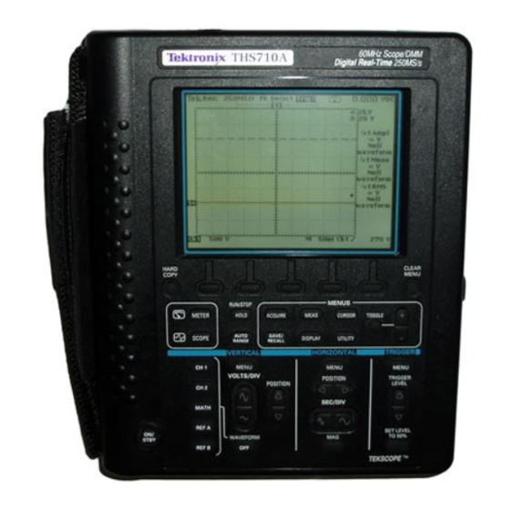
Getting Started In addition to a brief product description, this chapter covers the following topics: How to change the battery pack How to use external power How to use the tilt stand How to perform a quick functional check Product Description The THS710A, THS720A, THS730A, and THS720P TekScope instruments combine a two-channel oscilloscope and a digital multimeter (DMM) in a rugged, handheld package. - Page 15 Getting Started Oscilloscope Features The TekScope instrument is a powerful, two-channel oscilloscope with the following features: Autoranging for quick setup and hands-free operation 200 MHz (THS730A), 100 MHz (THS720A and THS720P) or 60 MHz (THS710A) bandwidth with selectable 20 MHz bandwidth limit 1 GS/s (THS730A), 500 MS/s (THS720A and THS720P), or 250 MS/s (THS710A) sample rate and 2,500 point record length...
- Page 16 Getting Started Meter Features The TekScope instrument is also a full-featured DMM with the following features: True RMS VAC, VDC, , continuity, and diode-check functions Autoranging or manual ranging Data logger plot of meter measurements over a period of time Max, min, delta max-min, relative-delta, and average statistics in the readout Bar graph for an “analog meter”...
- Page 17 Getting Started Input and Output Connectors All input and output connectors are located on the top and side panels as shown below. See the back of the instrument for maximum voltage ratings. WARNING. To avoid shock hazard, the DC input and I/O port hole plugs must remain closed in wet or damp conditions.
-
Page 18: Replacing The Battery Pack
Getting Started Replacing the Battery Pack For portable operation, use the rechargeable battery pack. You can replace the battery pack without losing any saved information. The current setup, saved setups, saved waveforms, and saved data are all stored in nonvolatile memory that does not depend on battery power. - Page 19 Getting Started Battery Life From a full charge, you can operate the TekScope instrument continuously for approximately two hours. You can extend the battery life by using automatic Power Off Time-out or Backlight Time-out. Refer to page 3–65 for a description of these features. The TekScope instrument turns off automatically when the battery runs low.
-
Page 20: Using External Power
Getting Started Using External Power Using external power from the AC adapter or cigarette lighter adapter has the following advantages: Saves internal battery power for portable operation later Charges internal battery pack Allows extended operation; the Standby Time-out and Backlight Time-out features are automatically disabled when external power is used Maintains floating measurement capability of the oscilloscope... -
Page 21: Using The Tilt Stand
Getting Started Using the Tilt Stand A built-in tilt stand folds out and snaps back into place when not in use. For benchtop use, lock the tilt stand in place with the hinged flap. To hang the TekScope instrument over a nail, rotate the tilt stand 180 . -
Page 22: Functional Check
Getting Started Functional Check After you install batteries or connect external power, you can perform this quick functional check to verify that your TekScope instrument is operating correctly. 1. Press the ON/STBY button to turn on the TekScope instrument. 2. After a few seconds, you should see a window with the message Power-On self check PASSED. - Page 23 Getting Started 5. Press the AUTORANGE button. Within a few seconds, you should see a square wave in the display (approximately 1.2 kHz). If you want, repeat steps 4 and 5 for channel 2 of the oscillo- scope. 6. Press the METER button. 7.
-
Page 24: Operating Basics
Operating Basics... -
Page 26: Functional Overview
Functional Overview This section covers the following topics: Understanding the front panel Using scope mode Using meter mode Connecting and using the probes Taking floating measurements You can find specific information about each of the controls in the Reference chapter of this manual. Understanding the Front Panel The front panel has buttons for the functions you use most often and menus to access more specialized functions. - Page 27 Functional Overview 1. Press a front-panel button to display the menu you want to use. 2. Press a bezel button to choose a menu item. If a pop-up menu appears, continue to press the bezel button to choose an item in the pop-up menu.
- Page 28 Functional Overview 3. Certain menu choices require you to set a numerical parameter to complete the setup. Use the /– rocker to adjust the parameter value or press the TOGGLE button to reset the parameter to its default value. 4. If the OK bezel button is displayed, press it to confirm your choice.
- Page 29 Functional Overview Using the Menu Buttons You can use the menu buttons below to perform many functions of the TekScope instrument. Many of these buttons operate differently in scope or meter mode. 1. ACQUIRE. Sets acquisition modes. Sets calculation mode of data logger. 2.
- Page 30 Functional Overview 3. MEASURE. Performs automated measurements of waveforms or data logger display. 4. DISPLAY. Changes appearance of waveform and display. Activates harmonics (THS720P only). Changes appearance of data logger display. 5. CURSOR. Activates scope or data logger cursors. 6. UTILITY. Activates system utility functions. 7.
- Page 31 Functional Overview Using the Dedicated Buttons You can use the dedicated buttons below to take direct actions. These buttons do not require the use of menus. 1. HARD COPY. Initiates a hard copy using the RS-232 port. 2. HOLD. Stops/restarts oscilloscope acquisition or holds/resets meter readout.
- Page 32 Functional Overview 4. CLEAR MENU. Clears menu from display. 5. TRIGGER LEVEL. Adjusts trigger level. 6. SET LEVEL TO 50%. Sets trigger level to midpoint of oscilloscope waveform. 7. HORIZONTAL POSITION. Adjusts oscilloscope waveform horizontal position. 8. MAG. Turns 10X horizontal magnification on and off. 9.
-
Page 33: Using Scope Mode
Functional Overview Using Scope Mode Press the front-panel SCOPE button to enter scope mode. Then, press AUTORANGE to set the vertical, horizontal, and trigger automatically for a usable display. The scope-mode display, shown below, is divided into four sections. Refer to SCOPE Mode on page 3–48 for a description of each section. -
Page 34: Using Meter Mode
Functional Overview Using Meter Mode Press the front-panel METER button to enter meter mode. Press one of the bezel buttons to choose a meter function and then press AUTORANGE to set the range automatically. The meter-mode display, shown below, is divided into three sections. Refer to METER Mode on page 3–39 for a description of each section and more information about the data logger and bar graph. -
Page 35: Compensating The Oscilloscope Probes
Functional Overview Compensating the Oscilloscope Probes To maintain signal fidelity, you must compensate each voltage probe for the channel input it is connected to. 1. Connect the oscilloscope probe and then press AUTORANGE. Ch 1 Probe reference lead to Probe tip to PROBE COMP AUTORANGE 2. -
Page 36: Compensating The Oscilloscope Signal Path
Functional Overview 3. If necessary, adjust the probe for correct compensation. P6117 P5102 4. Repeat these steps for the other probe and channel. Compensating the Oscilloscope Signal Path Signal path compensation optimizes the oscilloscope accuracy for the current ambient temperature. For maximum accuracy, recompen- sate the signal path if the ambient temperature changes by 5 C or more. -
Page 37: Taking Floating Measurements
Functional Overview Taking Floating Measurements This section covers important issues to consider when taking floating measurements. Architecture is Important For taking floating measurements, the TekScope instrument has an architectural difference from most other oscilloscopes. The channel 1, channel 2, and DMM inputs are isolated from the main chassis and from each other. - Page 38 Functional Overview Many handheld oscilloscope/DMM products have the architecture shown below, which shares a common reference for the oscilloscope channels and DMM. With this architecture, all input signals must have the same voltage reference when you take any multi-channel measurements. Other product architecture Oscilloscope channels and DMM must float together.
- Page 39 Functional Overview Attach the Reference Leads Correctly If you are using both of the oscilloscope channels, you must attach the probe reference lead for each channel directly to your circuit. These attachments are required because the oscilloscope channels are electrically isolated; they do not share a common chassis connection.
-
Page 40: General-Purpose Application Examples
General-Purpose Application Examples This section presents a series of general-purpose application examples. These simplified examples highlight the features of the TekScope instrument and give you ideas about using it to solve your own test problems. The first two examples demonstrate basic scope and meter operation. The remaining examples provide an overview of applications that cover the following areas: Digital circuit testing... -
Page 41: Displaying An Unknown Signal
General-Purpose Application Examples Displaying an Unknown Signal You need to see a signal in a circuit, but you have no previous knowledge of the signal amplitude, frequency, or shape. Connect the TekScope instrument to quickly display the signal. Ch 1 THS710A, THS720A, THS730A &... - Page 42 General-Purpose Application Examples Setup to Display an Unknown Signal SCOPE AUTO — — — RANGE The autorange feature sets the vertical, horizontal, and trigger automatically for a usable display. If the signal changes, the setup tracks those changes. Going Further If the autorange setup does not display the waveform exactly the way you like, you can easily change the setup.
-
Page 43: Measuring Resistance
General-Purpose Application Examples Measuring Resistance You need to probe a circuit to measure point-to-point resistance. Connect the TekScope instrument to measure a variety of resistance values. 29.23 k THS710A, THS720A, THS730A & THS720P User Manual 2–18... - Page 44 General-Purpose Application Examples Setup to Measure Resistance METER AUTO — — RANGE Going Further If a noisy environment causes an unstable resistance measurement, use the Average statistic to average the measurements. Refer to page 3–37 for more information. You can use the TekScope instrument as a continuity checker. With the setup below, it beeps when the measured resistance is 50 less (typical).
-
Page 45: Measuring The Frequency Of A Clock Signal
General-Purpose Application Examples Measuring the Frequency of a Clock Signal You suspect that the frequency of a TTL clock signal is out of tolerance. Connect the TekScope instrument to the signal to display it and measure its frequency. Ch 1 Ch 1 Freq 30.62 MHz... - Page 46 General-Purpose Application Examples Setup to Measure Clock Frequency AUTO — — SCOPE — RANGE Select Frequency MEAS Measmnt for OK Select — Measrmnt Going Further You can add peak-to-peak and duty cycle measurements to the display with the following additional steps: Select Page —...
-
Page 47: Measuring Propagation Delay
General-Purpose Application Examples Measuring Propagation Delay You suspect that the memory timing in a microprocessor circuit is marginal. Set up the TekScope instrument to measure the propaga- tion delay between the chip-select signal and the data output of the memory device. Ch 1 Ch 2 Data... - Page 48 General-Purpose Application Examples Setup to Measure Propagation Delay SCOPE CH 1 — — — CH 2 AUTO RANGE CURSOR Cursor V Bars Adjust first Function cursor, press TOGGLE, and then adjust second cursor If necessary, adjust the SEC/DIV rocker to optimize display for the propagation delay measurement.
-
Page 49: Triggering On A Missing Data Pulse
General-Purpose Application Examples Triggering on a Missing Data Pulse A positive-going TTL data pulse, 20 s wide, should occur at least once every millisecond. The circuit is not working correctly and you suspect an occasional missing pulse. Set up the TekScope instrument to find the missing pulse. - Page 50 General-Purpose Application Examples Setup to Find Missing Data Pulse SCOPE AUTO — — — RANGE TRIGGER Trigger Type Pulse MENU Trigger Source Polarity and Negative Set width to Width 1 ms Trigger When Greater Than — Width Mode Normal The TekScope instrument triggers if the signal remains in the low state longer than 1 ms.
-
Page 51: Detecting Narrow Glitches
General-Purpose Application Examples Detecting Narrow Glitches An elapsed-time counter circuit operates from a precision, 1 kHz square wave, clock signal supplied by another source. Occasionally, the counter counts too fast. You suspect glitches in the clock signal are causing the problem. Set up the TekScope instrument to look for glitches in the clock signal. - Page 52 General-Purpose Application Examples Setup to Detect Narrow Glitches SCOPE AUTO — — — RANGE ACQUIRE Acquire Mode Envelope Monitor the clock signal for several minutes. In Envelope acquisition mode, the TekScope instrument displays the 1 kHz square wave clock signal plus intermittent glitches that are as narrow as 8 ns. Going Further You can trigger on the glitch itself with the following setup: SCOPE...
-
Page 53: Triggering On A Third Signal
General-Purpose Application Examples Triggering on a Third Signal A metal forming machine produces an index pulse for each revolution of its main shaft. Connect the external trigger input of the TekScope instrument to the index pulse so you can monitor the output of two transducers while you vary the operating speed of the machine. - Page 54 General-Purpose Application Examples Setup to Use External Trigger SCOPE TRIGGER Trigger Type Edge — MENU Trigger External Source Connect the index pulse to the meter inputs, which now function as the external trigger input. Adjust the TRIGGER LEVEL rocker for stable triggering on the index pulse signal.
-
Page 55: Analyzing A Serial Data Communication Link
General-Purpose Application Examples Analyzing a Serial Data Communication Link You are having intermittent problems with a serial data communica- tion link and you suspect poor signal quality. Set up the TekScope instrument to show you a snapshot of the serial data stream so you can verify the signal levels and transition times. - Page 56 General-Purpose Application Examples Setup to Capture a Single Shot SCOPE AUTO — — — RANGE ACQUIRE Stop After Single Acquisition Sequence HOLD — — (RUN/STOP) Each time you press the HOLD (RUN/STOP) button, the instrument acquires a snapshot of the digital data stream. You can use the cursors or automatic measurements to analyze the waveform, or you can store the waveform to analyze later.
-
Page 57: Triggering On A Video Signal
General-Purpose Application Examples Triggering on a Video Signal The image quality is poor on a video monitor in a closed-circuit security system that uses the NTSC broadcast standard. Set up the TekScope instrument to display and trigger on the odd field of the video waveform coming into the monitor. - Page 58 General-Purpose Application Examples Setup to Trigger on the Odd Field SCOPE VERTICAL Probe Type Voltage Set to 1X MENU Probe AUTO — — — RANGE DISPLAY Display Style Set to 100 ms Accumulate Trigger Type Video TRIGGER — MENU Trigger On Odd Field Video Class NTSC...
- Page 59 General-Purpose Application Examples THS710A, THS720A, THS730A & THS720P User Manual 2–34...
-
Page 60: Power-Measurement Application Examples
Power-Measurement Application Examples This section presents a series of power-measurement application examples. These simplified examples highlight the features of the TekScope instrument and give you ideas about using it to solve your own test problems. These examples provide an overview of applications that cover the following areas: Power electronics testing Power quality testing... -
Page 61: Testing A Switching Transistor Drive Circuit
Power-Measurement Application Examples Testing a Switching Transistor Drive Circuit You need to evaluate the gate-drive circuit for a power FET (field-effect transistor) in a switching power supply. The gate-drive timing circuit is referenced to chassis ground. But the gate-drive signal is transformer-coupled to the FET, which is connected to a –300 VDC bus. - Page 62 Power-Measurement Application Examples Setup to Test the Transistor Drive Circuit SCOPE CH 1 — — — CH 2 AUTO RANGE You do not have to do anything special to take this difficult measurement. Because of the isolated channels, you can reference the channel 1 probe to chassis ground and the channel 2 probe directly to the –300 VDC bus.
-
Page 63: Measuring Instantaneous Power Dissipation In A Switching Transistor
Power-Measurement Application Examples Measuring Instantaneous Power Dissipation in a Switching Transistor The output transistor in a switching power supply is hotter than it should be. You are concerned about its peak power dissipation. Set up the TekScope instrument to measure the instantaneous power dissipation of the transistor using an optional current probe. - Page 64 Power-Measurement Application Examples Setup to Measure Instantaneous Power Dissipation SCOPE CH 1 — — — CH 2 Probe Type Current Set to Probe 100 mV/A AUTO — — — RANGE MATH Math Ch1 Ch2 Operation CURSOR Cursor Paired Set cursor Function Move the cursor along the power (MATH) waveform and read the instantaneous power in the cursor readout (for example, @5.63 W).
-
Page 65: Monitoring For Power Surges And Dropouts
Power-Measurement Application Examples Monitoring for Power Surges and Dropouts You are having intermittent problems with some electronic equipment that operates unattended at a remote site. You need to determine if the problem might be caused by momentary power quality problems in the electrical service to the equipment. Set up the TekScope instrument to monitor the line voltage for a week and capture any surges or dropouts that may occur. - Page 66 Power-Measurement Application Examples Setup to Monitor for Power Quality Problems METER — — — ACQUIRE Acquire Mode Peak Detect You can use the DMM data logger to record measurements over an extended period of time. Set the full-scale range to 400 V using the VOLTS/DIV rocker.
-
Page 67: Detecting A Missing Power Cycle
Power-Measurement Application Examples Detecting a Missing Power Cycle You suspect that power distribution switches are causing an infrequent, missing power cycle at the equipment you are servicing. Connect the TekScope instrument to detect a missing cycle on the 60 Hz AC power line. Ch 1 THS710A, THS720A, THS730A &... - Page 68 Power-Measurement Application Examples Setup to Detect a Missing Cycle SCOPE AUTO — — — RANGE TRIGGER Trigger Type Pulse MENU Trigger Source Polarity and Negative Set width to Width 20 ms Trigger When Greater Than — Width Mode Normal Set the trigger level to +50 V. The TekScope instrument triggers if one or more power cycles drop below a 50 V threshold.
-
Page 69: Measuring Harmonic Current (Ths720P)
Power-Measurement Application Examples Measuring Harmonic Current (THS720P) A three-phase power distribution system feeds an office that contains a lot of electronic equipment. Connect the TekScope instrument to analyze the harmonic current in the neutral conductor. Ch 2 100 mV/A THS710A, THS720A, THS730A & THS720P User Manual 2–44... - Page 70 Power-Measurement Application Examples Setup to Measure Harmonic Current SCOPE DISPLAY Harmonics — Show All from Select F to 11 THD Method THD-F — Probes Ch 2 Probe Set to 100 mV/A The TekScope instrument shows a bar-graph display of the harmonic current in the neutral conductor.
-
Page 71: Taking Power Measurements (Ths720P)
Power-Measurement Application Examples Taking Power Measurements (THS720P) In a manufacturing plant, the load on a particular branch circuit varies depending on the state of a process. You want to monitor the power supplied to this circuit over several days to measure the minimum and maximum load. - Page 72 Power-Measurement Application Examples Setup to Monitor Power SCOPE DISPLAY Harmonics — Probes Current Set to Probe CH 2 100 mV/A MATH — — — The TekScope instrument continuously measures voltage and current, and then calculates the power statistics shown in the box. Use the average, minimum, and maximum statistics to characterize the load on this branch circuit.
-
Page 73: Measuring Motor Start-Up Current
Power-Measurement Application Examples Measuring Motor Start-Up Current A circuit breaker trips when a motor starts. Connect the TekScope instrument to measure the transient current drawn by the motor before the circuit breaker trips. Ch 1 100 mV/A THS710A, THS720A, THS730A & THS720P User Manual 2–48... - Page 74 Power-Measurement Application Examples Setup to Measure Transient Current SCOPE CH 1 Probe Type Current Set to Probe 100 mV/A ACQUIRE Stop After Single — Acquisition Sequence HOLD — — (RUN/STOP) When you start the motor, the instrument captures the transient current and freezes the waveform in the display.
-
Page 75: Triggering At A Specific Motor Rpm
Power-Measurement Application Examples Triggering at a Specific Motor RPM You need to measure the start-up current of a 3600-RPM motor at several specific speeds. A tachometer, attached to the motor, outputs a low-voltage square wave with 100 pulses per revolution. Set up the TekScope instrument to trigger at 1200 RPM so you can measure the current at that speed. - Page 76 Power-Measurement Application Examples Setup to Trigger at 1200 RPM SCOPE CH 1 — — — CH 2 Probe Type Current Set to Probe 100 mV/A HORIZON- Trigger — TAL MENU Position TRIGGER Trigger Type Pulse MENU Trigger Source Polarity and Positive Set width to Width...
-
Page 77: Triggering On A Motor Drive Waveform (Ths720P)
Power-Measurement Application Examples Triggering on a Motor Drive Waveform (THS720P) You need to analyze the output waveform of a variable-speed AC motor drive. Connect the TekScope instrument to trigger on the output waveform of the motor drive. Motor drive Ch 1 THS710A, THS720A, THS730A &... - Page 78 Power-Measurement Application Examples Setup to Use Motor Trigger SCOPE AUTO — — — RANGE TRIGGER Trigger Type Motor MENU Adjust the TRIGGER LEVEL for a stable display. You can use motor trigger to stabilize the display of complex, pulse-width modulated, motor drive waveforms. Going Further You can use the horizontal MAG function to get a closer look at the motor drive waveform.
- Page 79 Power-Measurement Application Examples THS710A, THS720A, THS730A & THS720P User Manual 2–54...
-
Page 80: Reference
Reference... -
Page 82: Introduction To Reference
Introduction to Reference This chapter contains detailed information about the operation of the THS710A, THS720A, THS730A, and THS720P TekScope instruments. The topics in this chapter are arranged alphabetically by button name. Reference Topic Page Acquire 3–3 Autorange 3–8 Cursor 3–11 Display/Harmonics 3–13 Hard copy... - Page 83 Introduction to Reference THS710A, THS720A, THS730A & THS720P User Manual 3–2...
-
Page 84: Acquire
ACQUIRE ACQUIRE Press the ACQUIRE button to set acquisition parameters indepen- dently for scope mode and meter mode. Acquire Menu in Scope Mode Sample — SCOPE ACQUIRE Acquire Mode Peak Detect Envelope Set number Average of acquisi- tions Stop After HOLD Button —... - Page 85 ACQUIRE Samples acquired in four Acquisition Displayed record acquisition intervals mode points Interval 1 Interval 1 Sample Sample mode acquires one sample in each interval. Peak Detect Peak Detect mode uses the lowest and highest samples from two consecutive intervals. Use Sample acquisition mode for the fastest acquisition at Sample.
- Page 86 ACQUIRE Three acquisitions from one source Acquisition mode Acquisition 1 Envelope Envelope uses Peak Detect mode Finds highest and for each individual acquisition. lowest record points over many acquisitions Average Average uses Sample mode for Calculates average value each individual acquisition. for each record point over many acquisitions Envelope and Average.
- Page 87 ACQUIRE If you probe a noisy square wave signal that contains intermittent, narrow glitches, the waveform displayed will vary depending on the acquisition mode you choose. Sample Peak Detect Envelope Average Single Acquisition Sequence. The content of a single acquisition sequence depends on the acquisition mode.
- Page 88 ACQUIRE Acquire Menu in Meter Mode Acquire Mode Sample METER ACQUIRE Peak Detect Average On (Reset ) Key Points Acquisition Modes. The data logger compresses a sequence of meter measurements into a point and then plots a series of those points to form a graph.
-
Page 89: Autorange
AUTORANGE AUTORANGE Autorange automatically adjusts setup values to track a signal. If the signal changes, the setup continues to change to track the signal. Autorange works independently in scope and meter modes. Refer to page 3–16 for additional autorange information for the THS720P. The following controls are preset when you first select the autorange function. - Page 90 AUTORANGE These conditions start an autorange cycle. Scope Mode Meter Mode Too many or too few waveform DMM reading exceeds 3600 counts periods for a clear display of the or falls below 330 counts lower-numbered channel Waveform amplitude too large or too small compared to full screen if only one channel is displayed Waveform amplitude too large or too...
- Page 91 AUTORANGE These control changes turn off autorange. Scope Mode Meter Mode Change range (VOLTS/DIV) Change to Stop After Single Acquisi- tion Sequence Change VOLTS/DIV Change SEC/DIV Change trigger type Change trigger level Change trigger coupling Change trigger holdoff Change display format to XY Change display style THS710A, THS720A, THS730A &...
-
Page 92: Cursor
CURSOR CURSOR Press the CURSOR button to display the cursor menu. In scope mode, cursors operate on the 2500-point record of the selected waveform. In meter mode, they operate on the 250-point data logger plot. Cursor Function SCOPE CURSOR H Bars V Bars Paired Time Units... - Page 93 CURSOR Measuring Phase. Move the V Bar cursors to the 0 and 360 points and then press the Set 0 and 360 with V Bars button. Next, move either cursor to the point you want to measure. 4.16 V @ –1.78 V Horizontal Bar cursors 6.12 s @ 1.06 s...
-
Page 94: Display/Harmonics
DISPLAY/HARMONICS DISPLAY/HARMONICS Press the DISPLAY button to choose how waveforms are presented and to change the appearance of the display. In the THS720P TekScope instrument, the DISPLAY button is also used to activate harmonics functions. Refer to page 3–16 for a description of harmonics. - Page 95 DISPLAY/HARMONICS Key Points Display Style. Choose one of the following waveform display styles: Vectors fills the space between adjacent sample points in the display. Widely spaced points are filled using (sin x)/x interpolation. Dots displays only the individual sample points. Vector Accumulate adds persistence to the vector display.
- Page 96 NOTE. The above XY-display example shows the I-V characteristic of a switching power MOSFET. The current waveform, displayed in the vertical axis, is measured using a Tektronix A6302 current probe and AM503B current-probe amplifier. The following functions do not work in XY display format:...
- Page 97 DISPLAY/HARMONICS Display Menu in Harmonics Mode (THS720P) SCOPE DISPLAY Harmonics — — Show All from Select Odd from group of Even from harmonics Display Contrast — Set contrast THD Method THD-F — THD-R Probes Ch 1 Probe Set conver- Ch 2 Probe sion factor or probe attenuation...
- Page 98 DISPLAY/HARMONICS THD Calculation. Choose THD Method to specify whether Total Harmonic Distortion is calculated relative to the fundamental or to the RMS of the input signal. Harmonics Display (THS720P) Press CH 1 to display the voltage harmonics or press CH 2 to display the current harmonics.
- Page 99 DISPLAY/HARMONICS Status Line. The status line across the top of the display contains acquisition and trigger information similar to scope mode display. Refer to page 3–49 for more information. The harmonics indicator shows the currently selected harmonic. Press the /– rocker to display power measurements for the next/previous harmonic.
- Page 100 DISPLAY/HARMONICS Measurement Readouts. The area to the right of the graticule contains measurement readouts similar to scope mode display. Refer to page 3–53 for more information. Waveform Readout Lines. The readout lines below the graticule contain specific information about the waveform similar to scope mode display.
- Page 101 DISPLAY/HARMONICS Power Measurements (THS720P) When you press the MATH button, the TekScope instrument displays instantaneous power measurements based on the voltage and current waveforms. In the box, the instrument calculates power statistics that accumulate from the beginning of the acquisition. Power Explanation Measurements...
- Page 102 DISPLAY/HARMONICS Display Menu in Meter Mode Line Style Thin — METER DISPLAY Thick Display Contrast — Set contrast Graticule Full — Grid Cross Hair Frame Key Points Data Logger Line Style. For better visibility, choose Thick for a three-pixel-high data logger plot. The default (Thin) is one pixel high.
-
Page 103: Hard Copy
HARD COPY HARD COPY You can print a hard copy of the display if a printer is connected and properly configured. Press the HARD COPY button to start printing. If you do not want menus to show, press CLEAR MENU before you press HARD COPY. - Page 104 HARD COPY Setting Up to Print Perform the following steps to choose the printer and page layout: System Hard Copy SCOPE or UTILITY METER Layout Landscape Portrait Format three pages of formats Select Page — OK Select Format — The following printer and file formats are supported: BMP (Microsoft Windows file format) Deskjet (high resolution printer format) DPU 411/II, HC 411 (thermal printer format)
- Page 105 PC/AT or laptop with 9-pin male connector PC with 25-pin male connector Tektronix part number 103-0334-XX (supplied with HC 411) Radio Shack part number 26-1388 or equivalent Radio Shack part number 26-1495 or equivalent THS710A, THS720A, THS730A & THS720P User Manual...
- Page 106 HARD COPY Troubleshooting RS-232 Problems If the TekScope instrument and the personal computer or printer have trouble communicating, use the following steps to correct the problem: Verify that you are using the correct RS-232 cable and adapters. Determine whether your configuration requires a null-modem connection (where transmit/receive and control lines are switched) or a straight-through RS-232 connection.
-
Page 107: Hold
HOLD HOLD Press the HOLD (RUN/STOP) button to stop and start data acquisition. Because scope mode and meter mode have independent acquisition states, the HOLD button operates independently for these two modes. Hold Function in Scope Mode In scope mode, the function of the HOLD button depends on the Stop After selection in the acquire menu. -
Page 108: Horizontal Controls
HORIZONTAL Controls HORIZONTAL Controls You can use the horizontal controls to change the time base, horizontal position, and horizontal magnification of waveforms. Horizontal Operations in Scope Mode Main — SCOPE HORIZON- Time Base TAL MENU Delayed Runs Set delay time After Main Trigger Position Set to 10% —... - Page 109 HORIZONTAL Controls Key Points SEC/DIV Rocker. If waveform acquisition is stopped (using the HOLD button), changes you make to the time base have no effect until you restart acquisition. Roll Mode Display. To obtain a rolling display similar to a strip-chart recorder, select Auto trigger mode and set SEC/DIV to 500 ms/div or slower.
- Page 110 HORIZONTAL Controls Readout. The waveform readout shows the horizontal scale factor below the graticule. Page 3–48 shows the location of this readout. Time Base. Choose the Main or Delayed time base. The delayed time base runs at the preset delay time after the trigger event for the main time base.
- Page 111 HORIZONTAL Controls Horizontal Operations in Meter Mode METER HORIZONTAL — — MENU Key Points SEC/DIV Rocker. To adjust the scroll speed of the data logger plot, use the SEC/DIV rocker. If you change the scroll speed, data in the logger display is erased. Other Controls.
-
Page 112: Meas
MEAS MEAS You can use the MEAS button to access the automatic measurement capability of the TekScope instrument. In scope mode, the instrument measures the 2500-point, selected waveform. In meter mode, the measurements take the form of statistics, which are calculated from successive meter readings. - Page 113 MEAS Key Points Choosing Measurements. You can perform up to four automatic measurements on the selected waveform and display them along the right side of the graticule. The table beginning on page 3–35 describes the scope-mode measurements in detail. Power Measurements (THS720P). Refer to page 3–20 for information about power measurements.
- Page 114 MEAS High-Low Setup. The TekScope instrument determines the 10%, 50%, or 90% levels of the selected waveform and then uses them to calculate the measurements. You can choose the method used to determine these levels: Histogram sets the values statistically; it finds the most common value either above or below the midpoint (depending on whether it is defining the high or low reference level).
- Page 115 MEAS Measurement Gating. You can use the gating feature to limit measurements to the portion of the waveform that is between the cursors. When you turn gating on, the instrument displays vertical bar cursors. Use the /– rocker and TOGGLE button to move the cursors to the area of interest.
- Page 116 MEAS Scope-Mode Measurement Definitions Name Definition Ampl Measured over the entire waveform. Amplitude = High (100%) – Low (0%) BrstW The duration of a burst. Measured over the entire waveform. cMean The arithmetic mean over the first cycle in the waveform. cRMS The true Root Mean Square voltage over the first cycle in the waveform.
- Page 117 MEAS Scope-Mode Measurement Definitions (Cont.) Name Definition –Duty Measurement of the first cycle in the waveform. Negative Width Negative Duty Cycle 100% Period –Over Measured over the entire waveform. Low–Min Negative Overshoot 100% Amplitude –Width Measurement of the first negative pulse in the waveform. The time between the 50% amplitude points.
- Page 118 MEAS Measurements in Meter Mode Select Statistic METER MEAS — for DMM Max – Min Select Page — Statistic Choose statistic Remove Statistic All Statistics — Beep New Max-Min OK Select — Statistic OK Remove Statistic Key Points Data Included in Statistics. The statistics are calculated over all meter readings since the last reset.
- Page 119 MEAS Choosing Statistics. Choose up to three from the following statistics. Statistic Definition The maximum value of all meter readings since the last reset. The arithmetic average of all meter readings since the last reset. The minimum value of all meter readings since the last reset. The baseline value used in the Rel calculation.
-
Page 120: Meter Mode
METER Mode METER Mode Press the METER button to enter meter mode. The meter reading and statistics update about three times per second. — — METER — — — — — — (continuity) — — (diode) The meter-mode display, shown below, is divided into three sections. The next two pages identify the content of each section in detail. - Page 121 METER Mode Status Line The status line across the top of the display contains acquisition information. The overrange indicator warns when an overvoltage is applied to the input. Acquisition readout Overrange indicator The table below shows examples of the acquisition readout. Acquisition Readout Explanation...
- Page 122 METER Mode Graticule Area The graticule area contains the data logger plot, the bar graph, their scale markers, and the zoom factor readout. Data logger plot Upper vertical range marker Bar graph Reference level Lower vertical range marker Zoom factor Horizontal scale markers Measurement Readout Area The area above and to the right of the graticule contains the current...
- Page 123 METER Mode Data Logger Display The data logger records meter measurements over a period of time, creating a plot similar to a strip-chart recorder. You can set the time span of the plot from four minutes to eight days. The data logger plot scrolls to the left. The most recent data is always at the right end of the graticule.
- Page 124 METER Mode Zero Level. If you select the VDC meter function, the zero level is located at the horizontal centerline of the graticule; for all other meter functions, the zero level is the bottom of the graticule. Use the vertical POSITION rocker to move the zero level. Reference Level.
- Page 125 METER Mode Bar Graph The rapid update rate of the bar graph simulates an analog meter movement. The bar graph is displayed just to the right of the data logger display and uses the vertical axis of the data logger display as its scale.
-
Page 126: Save/Recall
SAVE/RECALL SAVE/RECALL Press the SAVE/RECALL button to save or recall any of the following: Setups Oscillscope waveforms DMM Data Save/Recall Menu in Scope Mode Save Current To Setup Choose setup SCOPE SAVE/ Setup location RECALL Recall Factory — Recall Saved Setup Setup Recall Setup... - Page 127 SAVE/RECALL Key Points Saving and Recalling Setups. Whether you save a setup in scope mode or meter mode, the TekScope instrument stores its complete setup in nonvolatile memory. When you recall the setup, you will be in the mode from which the setup was saved. Recalling the Factory Setup.
- Page 128 SAVE/RECALL Save/Recall Menu in Meter Mode Save Current To Setup Choose setup METER SAVE/ Setup location RECALL Recall Factory — Recall Saved Setup Setup Recall Setup Choose setup location Save DMM To Data Choose DMM Data data location Recall DMM Recall Data Data Clear Data...
-
Page 129: Scope Mode
SCOPE Mode SCOPE Mode Press the SCOPE button to enter scope mode. If already in scope mode, pressing this button has no effect. The scope-mode display, shown below, is divided into four sections. The next five pages identify the content of each section in detail. Status line Graticule Measurement... - Page 130 SCOPE Mode Status Line The status line across the top of the display contains acquisition and trigger information. Acquisition readout Trigger status Additional items The table below shows acquisition readout examples that are displayed when acquisition is running. When you press HOLD to stop acquisition, the readout shows the number of waveforms acquired since acquisition was last stopped.
- Page 131 SCOPE Mode The table below shows examples of additional items that are sometimes displayed in the status line. Additional Items Explanation DMM icon and current DMM reading Parameter and its current value (only when the /– rocker is assigned to a parameter) Indicates that the DMM input is being used for external trigger.
- Page 132 SCOPE Mode Waveform Readout Lines The readout lines below the graticule contain specific information about displayed waveforms. The top line displays vertical readout for channel 1 and channel 2. The bottom line displays readout for Ref A, Ref B, or Math, whichever waveform was selected last. Vertical readouts The table below shows examples of the vertical readout symbols.
- Page 133 SCOPE Mode The waveform readout lines also show time base and trigger information. Main or Trigger delayed information time base Reference waveform time base The table below shows examples of time base information. Time Base Information Explanation Main time base Delayed time base The table below shows examples of the trigger information.
- Page 134 SCOPE Mode Measurement Readout Area The area to the right of the graticule contains cursor and measure- ment readouts. If a measurement qualifier appears with a measure- ment result, the signal may be insufficient to take an accurate measurement. Cursor readouts Measurement readouts Measurement qualifier For More Information...
-
Page 135: Trigger Controls
TRIGGER Controls TRIGGER Controls Triggering is an oscilloscope-only function; the trigger controls, shown below, have no effect in meter mode. The trigger types are the following: Edge triggers on the rising or falling edge of the input signal (see page 3–56). Pulse triggers on specific events that you can qualify by time (see page 3–58). - Page 136 TRIGGER Controls Edge or Motor Pulse Video Choose Ch 1, Ch 2, Choose Ch 1 or Ch 2 Choose Ch 1 or Ch 2 or External (Edge only) Odd Field Positive (Interlaced) Even Field Negative Reject (Interlaced) Any Field Reject (Non-interlaced) Lines Noise Rej (DC Low...
- Page 137 TRIGGER Controls Edge Trigger Use Edge triggering to trigger on the rising or falling edge of the input signal at the trigger threshold. Trigger Type Edge SCOPE TRIGGER — MENU Trigger Source Ext. [DMM] Trigger Coupling HF Reject (Ch 1 or Ch 2 LF Reject source only) Noise Reject...
- Page 138 TRIGGER Controls Holdoff. You can use holdoff to help stabilize the display of complex waveforms. After you press the Mode & Holdoff menu button, use /– rocker to set the holdoff time from 500 ns to 10 s. Holdoff begins when the TekScope instrument recognizes a trigger event and disables the trigger system until acquisition is complete.
- Page 139 TRIGGER Controls Pulse Trigger Use Pulse triggering to isolate and display specific events that you can qualify by time. Trigger Type Pulse SCOPE TRIGGER — MENU Trigger Source Polarity & Positive Set width Width Negative Less Than — Trigger When Width Greater Than Width...
- Page 140 TRIGGER Controls Equal To Width triggers on a pulse that matches the set pulse width within a given tolerance. Use the /– rocker to set the tolerance in percent. For example, if the pulse width is set to 1 s and the tolerance is set to 20%, triggering occurs only on pulse widths in the range from 800 ns to 1.2 s.
- Page 141 TRIGGER Controls Video Trigger Choose video triggering to trigger on a specific line in the odd or even field, or on all the lines of an NTSC, PAL, or SECAM standard video signal. Also, you can trigger on nonstandard video signals with scan rates up to 65 kHz.
- Page 142 TRIGGER Controls Motor Trigger (THS720P) Choose motor triggering to trigger on the rising or falling edge of a bipolar, motor drive waveform. Trigger Type Motor SCOPE TRIGGER — MENU Trigger Source Trigger Coupling Trigger Slope / (rising edge) \ (falling edge) Mode &...
-
Page 143: Utility
UTILITY UTILITY The following are examples of what you can do with each of the six branches in the Utility menu: Use Config to display the firmware version. Use Hard Copy to set up hard copy parameters. Refer to HARD COPY on page 3–22 for information about setting up and printing a hard copy. - Page 144 UTILITY Config System System Config SCOPE or UTILITY METER Tek Secure Erase — Memory Version OK Erase Setup/Data Key Points Tek Secure. If you have acquired confidential data, you may want to execute Tek Secure before you return the TekScope instrument to general use.
- Page 145 UTILITY RS-232 System System RS-232 — SCOPE or UTILITY METER Baud Rate — Choose rate Hard Flagging Flagging Soft Flagging Misc CR/LF LF/CR Parity None Even Stop Bits Delay Set delay Set RS232 — — Parameters to Defaults Key Points RS-232 Troubleshooting.
- Page 146 UTILITY Misc System System Misc — SCOPE or UTILITY METER Power Off — Set time Time-Out Backlight Time- — Set time Key Points Power Off Time-Out. Use this feature to automatically turn off the TekScope instrument if it is not being used. Use the /–...
- Page 147 Factory Scope and Factory DMM. Service personnel use these functions to calibrate the oscillscope and DMM internal voltage references. Refer to your Tektronix field office or representative for assistance with these processes. THS710A, THS720A, THS730A & THS720P User Manual 3–66...
- Page 148 UTILITY Diag System System Diag SCOPE or UTILITY METER Execute — Loop Once Always Until Fail Error Log — OK Run Test OK Display Log Key Points Starting Diagnostics. To execute the built-in diagnostic routines, disconnect all cables, probes, or leads from the oscilloscope and DMM inputs, and then press the OK Run Test button.
-
Page 149: Vertical Controls
VERTICAL Controls VERTICAL Controls You can use the vertical controls to display waveforms, adjust vertical scale and position, and set input parameters. In the THS720P TekScope instrument, the vertical controls are also used to display waveform harmonics. Refer to page 3–16 for a description of harmonics. - Page 150 VERTICAL Controls Channel 1 or Channel 2 Vertical Menu The vertical menu contains the following items when channel 1 or channel 2 is the selected waveform. Coupling SCOPE VERTICAL — MENU Invert Invert Off Invert On Bandwidth Full Bandwidth 20 MHz Position —...
- Page 151 VERTICAL Controls Math Vertical Menu The vertical menu contains the following items when Math is the selected waveform. SCOPE VERTICAL Math Operation Ch1 + Ch2 — MENU Ch1 – Ch2 Ch2 – Ch1 Ch1 Ch2 Key Points Math Waveform Units. The waveform math function recognizes the following combinations of units.
- Page 152 VERTICAL Controls Ref A or Ref B Vertical Menu The vertical menu contains the following items when Ref A or Ref B is the selected waveform. Save Ch1 SCOPE VERTICAL To Waveform Choose wave- MENU form location Save Ch2 Save MATH Horizontal Lock —...
- Page 153 VERTICAL Controls Vertical Operations in Meter Mode Position — Set position METER VERTICAL MENU Zoom — Noise Reject None 60 Hz 50 Hz Volts — Volts Scale Set reference voltage dBm into Set impedence Current Probe Set conversion Probe Type factor Voltage Probe —...
- Page 154 VERTICAL Controls Key Points Zoom. You can get a close view of the data logger plot using the Zoom selection. The plot is vertically enlarged around the center of the screen for the VDC function, and around the bottom of the screen for other meter functions.
- Page 155 VERTICAL Controls THS710A, THS720A, THS730A & THS720P User Manual 3–74...
-
Page 156: Appendices
Appendices... -
Page 158: Appendix A: Specifications
Appendix A: Specifications This appendix contains the oscilloscope, DMM, and general specifications for the THS710A, THS720A, THS730A, and THS720P TekScope instruments. All specifications are guaranteed unless noted as “typical.” Typical specifications are provided for your convenience but are not guaranteed. Specifications that are marked with the symbol are checked in Appendix D: Performance Verification. - Page 159 Appendix A: Specifications Oscilloscope Specifications (Cont.) Inputs Input Coupling DC, AC, or GND Input Impedance, 1% in parallel with 25 pF 2 pF DC Coupled Maximum Voltage Overvoltage Category Maximum Voltage Be ee Between Signal and CAT II Environment (refer to 300 V Common at Input BNC page A–19)
- Page 160 Appendix A: Specifications Oscilloscope Specifications (Cont.) Vertical Number of Channels Digitizers 8 bit resolution, separate digitizers for each channel sample simultaneously VOLTS/DIV Range 5 mV/div to 50 V/div at input BNC Polarity Normal and Invert Position Range 10 divisions THS710A THS720A THS720P THS730A...
- Page 161 Appendix A: Specifications Oscilloscope Specifications (Cont.) Vertical DC Measurement Measurement Type Accuracy Accuracy, Average A er e Absolute voltage measure- [2% |reading + Acquisition Mode ments (position volts/div)| + Using 16 Waveforms (0.1 div volts/div)] Delta voltage between any two [2% |reading| + waveforms acquired under (0.05 div volts/div)]...
- Page 162 Appendix A: Specifications Oscilloscope Specifications (Cont.) Internal Trigger Trigger Sensitivity, Coupling Sensitivity Edge Trigger Type d e Tr er T e 0.35 div from DC to 50 MHz, (THS710A, THS 720A, increasing to 1 div at 100 MHz and THS720P) (90 MHz above 35 C) Coupling Sensitivity...
- Page 163 Appendix A: Specifications Oscilloscope Specifications (Cont.) Internal Trigger Width Range, Pulse 99 ns to 1 s, with resolution of 33 ns or approximately 1% of Trigger Type, typical setting (whichever is greater) Width Tolerance 5%, 10%, 15%, or 20% Range, Pulse Trigger Type, typical Sensitivity, Video Composite video signal with negative sync pulse amplitude from...
- Page 164 Appendix A: Specifications Oscilloscope Specifications (Cont.) External Trigger External Trigger, 600 V CAT II, 300 V CAT III (refer to page A–19) Maximum Input Voltage External Trigger DC only Coupling External Trigger Levels +0.2 V or +2 V, selectable External Trigger Sensi- 500 mV from DC to 1 MHz, increasing to 1 V at 5 MHz, with...
- Page 165 Appendix A: Specifications Oscilloscope Specifications (Cont.) Voltage and Current Harmonics (THS720P) Number of Harmonics First 31 harmonics of signal with fundamental frequency between 30 Hz and 450 Hz Harmonics Amplitude Accuracies below are stated as a percent of the fundamental Accuracy amplitude and are valid only if peak-to-peak amplitude is 4 divisions and number of averages 16...
- Page 166 Appendix A: Specifications Oscilloscope Specifications (Cont.) Power Measurements (THS720P) True Power Measure- ment measured over an integral number of cycles that contain n sample points Apparent Power Mea- surement Reactive Power Mea- (VA) surement Power Measurements 4% at the BNCs (not including probe uncertainty) Accuracy PF Measurement true power...
- Page 167 Appendix A: Specifications Oscilloscope Specifications (Cont.) With P6117 Probe Analog Bandwidth, DC THS710A THS720A THS720P THS730A Coupled 60 MHz 100 MHz 100 MHz 200 MHz (90 MHz (90 MHz (180 MHz above 35 C) above 35 C) above 35 C) Probe Attenuation Maximum Voltage Overvoltage Category...
- Page 168 Appendix A: Specifications Oscilloscope Specifications (Cont.) With P5102 Probe Analog Bandwidth, DC THS710A THS720A THS720P THS730A Coupled 60 MHz 100 MHz 100 MHz 100 MHz (90 MHz (90 MHz above 35 C) above 35 C) Probe Attenuation Maximum Voltage Overvoltage Category Maximum Voltage Be ee Between Probe Tip and...
- Page 169 Appendix A: Specifications DMM Specifications General Resolution digit, 4000 count full scale reading except as noted Input Resistance, AC 10 M or DC Voltage Input Capacitance, AC 100 pF or DC Voltage, typical Maximum Voltage Overvoltage Category Maximum Voltage Be ee D Between DMM and CAT I Environment (refer to 640 V...
- Page 170 Appendix A: Specifications DMM Specifications (Cont.) DC Voltage Accuracy (0.5% of reading + 5 counts) Normal Mode Rejects AC signals by >60 dB at 50 Hz or 60 Hz (user selectable) Rejection, typical Common Mode Rejects AC signals by >100 dB at 50 Hz or 60 Hz (user Rejection, typical selectable) AC Voltage...
- Page 171 Appendix A: Specifications DMM Specifications (Cont.) /Resistance Ranges and Resolution Range Resolution 400.0 4.000 k 40.00 k 400.0 k 4.000 M 40.00 M 10 k Accuracy Range Maximum Error (0.5% of reading + 2 counts) All ranges except 40 M (2% of reading + 5 counts) for 40 M 60% relative humidity...
- Page 172 Appendix A: Specifications DMM Specifications (Cont.) Continuity Check Indication, typical An audible tone is generated when measured resistance is below Open Circuit Voltage, typical Test Current, typical 1 mA Diode Check Range Zero to 2 V, measures forward voltage drop of semiconductor junction Voltage Accuracy, typical...
- Page 173 Appendix A: Specifications General Specifications (Cont.) RS-232 Interface Device Type DTE, at RJ-45 connector Pinout Signal Pin Number at Pin Number at RJ-45 9-pin Null Connector Modem Adapter RTS out TXD out RXD in DTR out CTS in RTS out DSR in (not used) DCD in (not used) Probe Compensator Output...
- Page 174 Appendix A: Specifications General Specifications (Cont.) Power Source Battery Replaceable Ni-Cd battery pack Battery Life, typical Approximately two hours of continuous use from a full charge Low Battery Indication, Low battery message first appears approximately ten minutes typical before the instrument powers off automatically Battery Saver Standby Time-out and Backlight Time-out extend battery life.
- Page 175 Appendix A: Specifications General Specifications (Cont.) Environmental Temperature Operating –10 C to +50 C Nonoperating –20 C to +60 C Humidity +40 C or below 95% relative humidity +41 C to +50 C 75% relative humidity Altitude Operating 2,000 m Nonoperating 15,000 m Random Vibration...
- Page 176 Appendix A: Specifications General Specifications (Cont.) Mechanical Size Height 8.53 in (217 mm) Width 6.95 in (177 mm) Depth 2.00 in (50.8 mm) Weight With battery installed 3.2 lbs (1.5 kg) With all standard 7.5 lbs (3.4 kg) accessories in soft carry case When packaged for 9.0 lbs (4.1 kg)
- Page 177 IEC 801–4 Fast Transients IEC 801–5 Surge EN 61010–1 /A2 Safety Tektronix-supplied ferrite bead required on instrument end of RS-232 cable Performance criteria: 5.0 div increase in peak-to-peak noise (Sample acquisition mode, full bandwidth); otherwise, 1.0 div increase in peak-to-peak noise...
-
Page 178: Appendix B: Factory Setup
Appendix B: Factory Setup The table below lists the state of the TekScope instrument after you recall the Factory Setup. Control Changed by Factory Setup to Acquire mode Sample Acquire stop after HOLD button only Acquire # of averages Acquire # of envelopes Channel selection Channel 1 on, all others off Cursor H Bar 1 position... - Page 179 Appendix B: Factory Setup Control Changed by Factory Setup to Display style Vectors Display trigger “T” Display accumulate time 500 ms DMM mode – autorange DMM function DC volts DMM mode – scope on/off Edge trigger coupling Edge trigger level 0.0 V Edge trigger slope Rising...
- Page 180 Appendix B: Factory Setup Control Changed by Factory Setup to Trigger type Edge Vertical bandwidth (all channels) Full Vertical coupling (all channels) Vertical position (all channels) 0 div Vertical volts/div. (all channels) 100 mV/div Volts scale Volts THS710A, THS720A, THS730A & THS720P User Manual B–3...
- Page 181 Appendix B: Factory Setup THS710A, THS720A, THS730A & THS720P User Manual B–4...
-
Page 182: Appendix C: Accessories
Appendix C: Accessories Standard Accessories P6117 10X Passive Probes (THS730A, THS720A, and THS710A) The P6117 10X passive probes have 200 MHz bandwidth and a CAT II voltage rating of 300 V . These probes are suitable for floating measurements up to 30 V P5102 10X Passive Probes (THS720P) The P5102 10X passive probes have 100 MHz bandwidth and a CAT II voltage rating of 1000 V... - Page 183 Appendix C: Accessories Standard Accessories (Cont.) RS-232 Cable and Adapter This RS-232 cable set (012-1533-00) includes a 2 m cable with RJ-45 connectors on each end. The set also includes a 9-pin adapter (103-0403-00) to connect to PCs. Soft Case The soft case (016-1399-01) protects the TekScope instrument when not in use.
- Page 184 Appendix C: Accessories Optional Accessories P5102 10X Passive Probes (THS730A, THS720A, and THS710A) The P5102 10X passive probes have 100 MHz bandwidth and a CAT II voltage rating of 1000 V . These probes are suitable for floating measurements up to 600 V Deluxe Meter Lead Set The deluxe pair of meter leads (ATLDX1) uses a sheathed banana-jack interface that is compatible with a variery of probing...
- Page 185 AC power adapter, battery charger, spare battery, and manuals. A621 and A622 Current Probes Two Tektronix current probes extend the TekScope instrument to handle current and power measurements. These clamp-on probes do not require disconnections to insert them into the circuit.
- Page 186 Appendix C: Accessories Optional Accessories (Cont.) A605 and A610 Current Probes These busbar-style current probes have banana plug connectors to measure current using the DMM. A605: AC only, 500 A max, 48 Hz to 1 kHz, 1 mV/A A610: AC or DC, 500 A max, DC to 440 Hz, 1 mV/A P6408 Word Recognizer Trigger Probes The P6408 is a 16-bit word recognizer probe for TTL logic operating at clock rates up to 20 MHz.
- Page 187 Appendix C: Accessories THS710A, THS720A, THS730A & THS720P User Manual C–6...
-
Page 188: Appendix D: Performance Verification
3% amplitude accuracy Time Mark Generator 10 ms period, 50 ppm accuracy Banana to Banana Shielded banana jacks Tektronix Deluxe Meter Cable (two required) on each end Lead Set (ATLDX1) BNC Cable BNC male to BNC male, Tektronix part number... -
Page 189: Test Record
Appendix D: Performance Verification Test Record Serial Procedure Performed by Date Number Test Passed Failed Self Test Oscilloscope Tests Low Limit Test Result High Limit Channel 1 5 mV/div 34.05 mV 35.95 mV DC e s re DC Measure- 500 mV/div 3.405 V 3.595 V ment Accu-... - Page 190 Appendix D: Performance Verification DMM Tests Low Limit Test Result High Limit DC Voltage 400 mV 59.2 mV 60.8 mV Accuracy range, 60 mV input 400 mV 357.7 mV 362.3 mV range, 360 mV input 4 V range 3.577 V 3.623 V 40 V range 35.77 V...
-
Page 191: Performance Verification Procedures
Appendix D: Performance Verification Performance Verification Procedures Before beginning these procedures, two conditions must first be met: The TekScope instrument must have been operating continuously for ten minutes in an 18 C to 28 C ambient environment with a relative humidity of less than 60%. You must perform the Compensate Signal Path operation described on page 2–11. - Page 192 Appendix D: Performance Verification Self Test This procedure uses internal routines to verify that the TekScope instrument functions and passes its internal self tests. No test equipment or hookups are required. Start the self test with the following setup: SCOPE System Diag UTILITY...
- Page 193 Appendix D: Performance Verification Check DC Measurement Accuracy 1. Set the DC voltage source output level to 0 V. 2. Set up the TekScope instrument using the following steps: Recall Saved Recall Factory SCOPE SAVE/ — Setup Setup RECALL OK Recall —...
- Page 194 Appendix D: Performance Verification 4. For each VOLTS/DIV setting listed below, perform the following steps: a. Set the DC voltage source output level to the positive voltage listed and then record the mean measurement as V b. Reverse the polarity of the DC voltage source and then record the mean measurement as V c.
- Page 195 Appendix D: Performance Verification Check Channel 1 Bandwidth 1. Set up the TekScope instrument using the following steps: Recall Saved Recall Factory SCOPE SAVE/ — Setup Setup RECALL OK Recall — Factory ACQUIRE Acquire Mode Average Set to 16 TRIGGER Trigger Noise Reject —...
- Page 196 Appendix D: Performance Verification 3. Set the TekScope instrument VOLTS/DIV to 100 mV/div. 4. Set the TekScope instrument SEC/DIV to 10 s/div. 5. Set the leveled sine wave generator frequency to 50 kHz. 6. Set the leveled sine wave generator output level so the peak-to- peak measurement is between 599 mV and 601 mV.
- Page 197 Appendix D: Performance Verification Check Channel 2 Bandwidth 1. First check the channel 1 bandwidth using the previous test. Then, perform these additional steps to check the channel 2 bandwidth: CH 1 SCOPE — — — WAVE- FORM CH 2 TRIGGER Trigger Source Gating &...
- Page 198 Appendix D: Performance Verification 3. Set the TekScope instrument VOLTS/DIV to 100 mV/div. 4. Set the TekScope instrument SEC/DIV to 10 s/div. 5. Set the leveled sine wave generator frequency to 50 kHz. 6. Set the leveled sine wave generator output level so the peak-to- peak measurement is between 599 mV and 601 mV.
- Page 199 Appendix D: Performance Verification Check Sample Rate and Delay Time Accuracy 1. Set up the TekScope instrument using the following steps: Recall Saved Recall Factory SCOPE SAVE/ — Setup Setup RECALL OK Recall — Factory VERTICAL Probe Type Voltage Probe Set to 1X MENU 2.
- Page 200 Appendix D: Performance Verification 6. Press SET LEVEL TO 50%. 7. Press MAG. 8. Change the TekScope instrument setup using the following steps: HORIZON- Time Base Delayed Runs SCOPE — TAL MENU After Main CLEAR — — MENU 9. Set the delayed time base to 50 ms/div. 10.
- Page 201 Appendix D: Performance Verification Check Channel 1 Edge Trigger Sensitivity 1. Set up the TekScope instrument using the following steps: Recall Saved Recall Factory SCOPE SAVE/ — Setup Setup RECALL OK Recall — Factory ACQUIRE Acquire Mode Average Set to 16 TRIGGER Trigger Mode Normal...
- Page 202 Appendix D: Performance Verification 3. Set the leveled sine wave generator frequency to 200 MHz if you are checking a THS730A or to 100 MHz if you are checking a THS710A, THS720A or THS720P. 4. Set the TekScope instrument VOLTS/DIV to 500 mV/div. 5.
- Page 203 Appendix D: Performance Verification Check Channel 2 Edge Trigger Sensitivity 1. First check the channel 1 edge trigger sensitivity using the previous test. Then, perform these additional steps to check the channel 2 edge trigger sensitivity. CH 1 SCOPE — —...
- Page 204 Appendix D: Performance Verification 3. Set the leveled sine wave generator frequency to 200 MHz if you are checking a THS730A or to 100 MHz if you are checking a THS710A, THS720A or THS720P. 4. Set the TekScope instrument VOLTS/DIV to 500 mV/div. 5.
- Page 205 Appendix D: Performance Verification Check DC Voltage Accuracy 1. Set the DC voltage source output level to 0 V. 2. Set up the TekScope instrument using the following steps: METER — — 3. Connect the TekScope instrument to the DC voltage source as shown below.
- Page 206 Appendix D: Performance Verification 4. For each range, set the DC voltage source output to the level listed below, and then compare the meter reading to the accuracy limits. DC Voltage Source Range Output Level Accuracy Limits 400 mV 60 mV 59.2 mV to 60.8 mV 400 mV 360 mV...
- Page 207 Appendix D: Performance Verification Check AC Voltage Accuracy 1. Set the AC voltage source output level to 0 V. 2. Set up the TekScope instrument using the following steps: METER — — 3. Connect the TekScope instrument to the AC voltage source as shown below.
- Page 208 Appendix D: Performance Verification 4. Set the AC voltage source output frequency to 500 Hz. 5. For each range, set the AC voltage source output to the level listed below, and then compare the meter reading to the accuracy limits. AC Voltage Source Range Accuracy Limits...
- Page 209 Appendix D: Performance Verification Check Resistance Accuracy 1. Set up the TekScope instrument using the following steps: METER — — 2. Connect the TekScope instrument to the resistance standard as shown below. Resistance standard Banana cables THS710A, THS720A, THS730A & THS720P User Manual D–22...
- Page 210 Appendix D: Performance Verification 3. For each range, set the resistance standard to the resistance listed below, and then compare the meter reading to the accuracy limits. Resistance Standard Range Setting Accuracy Limits 358.0 to 362.0 3.6 k 3.580 k to 3.620 k 40 k 5.95 k to 6.05 k 40 k...
- Page 211 Appendix D: Performance Verification THS710A, THS720A, THS730A & THS720P User Manual D–24...
-
Page 212: Appendix E: General Care And Cleaning
Appendix E: General Care and Cleaning General Care Protect the TekScope instrument from adverse weather conditions. The instrument is not waterproof. Do not store or leave the instrument where the LCD display will be exposed to direct sunlight for long periods of time. CAUTION. - Page 213 Appendix E: General Care and Cleaning THS710A, THS720A, THS730A & THS720P User Manual E–2...
-
Page 214: Glossary And Index
Glossary and Index... - Page 216 Glossary /– Rocker The general-purpose rocker button on the front panel that you can use to set parameters. The specific parameter assigned to the /– rocker depends on other selections. AC Coupling A mode that blocks the DC component of a signal but passes the dynamic (AC) component of the signal.
- Page 217 Glossary Attenuation The degree the amplitude of a signal is reduced when it passes through an attenuating device such as a probe or attenuator (the ratio of the input measure to the output measure). For example, a 10X probe attenuates, or reduces, the input voltage of a signal by a factor of 10.
- Page 218 Glossary Common Lead The meter lead attached to the reference voltage in a measure- ment application. Because of the isolated channels, the meter common lead and the scope reference leads do not have to be connected to the same reference voltage. Continuity A test to verify electrical conductivity from one point to another.
- Page 219 Glossary Diode Test A test to verify polarity and measure the forward voltage drop of a semiconductor junction. Displacement Power Factor (DPF) Cosine of the phase angle between fundamental components of the voltage and current waveforms. Display The word used to refer to the screen or the LCD (liquid crystal display).
- Page 220 Glossary Ground (GND) Coupling Coupling option that disconnects the input signal from the vertical system. Hard Copy An electronic copy of the display in a format useable by a printer or plotter. Harmonics Voltage or current waveforms having frequencies that are integer multiples of the base (fundamental) frequency.
- Page 221 Glossary Menu A set of labels shown in the display to identify the functions of the bezel buttons. The specific menu contents depend on the menu button you press. Motor Trigger Triggering on the rising or falling edge of a bipolar, motordrive waveform.
- Page 222 Glossary Power Factor (PF) The ratio of true power (watts) to apparent power (volt- amperes). Pretrigger The specified portion of the waveform record that contains data acquired before the trigger event. Pulse Trigger Triggering on events that you can qualify by time. The oscilloscope triggers when an incoming pulse width meets time criteria you have defined.
- Page 223 Glossary Roll Mode An acquisition mode useful at slow horizontal scale settings. Roll mode allows you to view the waveform as it is acquired point-by-point. The waveform appears to roll across the display. RS-232 The serial communication port used to connect to a hard-copy device, computer, controller, or terminal.
- Page 224 Glossary Signal Path Compensation (SPC) The ability of the oscilloscope to minimize the electrical offsets in the vertical, horizontal, and trigger amplifiers caused by ambient temperature changes and component aging. You should run SPC when the ambient temperature varies more than 5 C from the last SPC or before performing critical measurements.
- Page 225 Glossary Vertical Bar Cursors The two vertical bars you position to measure the time parameter of a waveform record. The oscilloscope displays the value of the active (moveable) cursor with respect to trigger and the time value between the bars. Video Trigger Triggering on the sync pulse of a composite video signal.
- Page 226 Index AUTORANGE button, 2–6 accessories, C–1 turning off, 3–10 ACQUIRE button, 2–4, 3–3 turning on, 3–8 acquisition average statistic, 3–38 modes, 3–3 averaging, 3–3 status, 3–40, 3–49 amplitude measurement, 3–35 applications analyzing serial data communica- backlight, 3–65 tion link, 2–30 bandwidth limit, 3–69 detecting glitches, 2–26 bar graph, 3–44...
- Page 227 Index CURSOR button, 2–5, 3–11 cursors application example, 2–22 factory setup readouts, 3–12, 3–41 detailed description, B–1 using, 3–11 recalling, 3–46 cycle mean measurement, 3–35 fall time measurement, 3–35 cycle RMS measurement, 3–35 features automatic measurements, 2–20 cursors, 2–22 data logger, 2–40 dot accumulate, 2–32 data logger isolated channels, 2–12, 2–36...
- Page 228 Index high level measurement, 3–35 measurement applications high voltage, warning, 2–14 continuity, 2–19 HOLD button, 3–26 data logger, 2–40 holdoff, 3–57 diode junction, 2–19 HORIZONTAL MENU button, floating, 2–12, 2–36 2–5, 3–27 frequency, 2–20 motor current, 2–50 phase, 3–12 power, 2–38, 2–46 propagation delay, 2–22 input protection, A–2, A–10, A–11, resistance, 2–18...
- Page 229 Index METER button, 3–39 phase measurement, 3–12 meter mode position features, 1–3 data logger, 3–43 how to use, 2–9 horizontal, 3–28 min measurement, 3–35 of reference waveforms, 3–71 min statistic, 3–38, 3–44 trigger, 3–29 motor trigger, how to use, 3–61 vertical, 3–68 positive duty cycle measurement, 3–36...
- Page 230 Index SEC/DIV rocker meter mode, 3–30 readouts scope mode, 3–28 cursors, 3–12 selected waveform DMM reading, 3–41, 3–50 how to select, 3–68 measurements, 3–19, 3–53 indicator, 3–50 power measurements, 3–20 self test, 3–67 time base, 3–52 SET LEVEL TO 50% button, 2–7 trigger, 3–52 setups waveform, 3–19, 3–51...
- Page 231 Index triggering Auto mode, 3–56 edge trigger, 3–56 vectors, 3–13 external trigger, 3–56 VERTICAL MENU button, 2–5, motor trigger, 3–61 3–68 Normal mode, 3–56 video trigger on AC line, 2–29 application examples, 2–32 on glitches, 2–27 how to use, 3–60 on missing pulse, 2–24 sync pulses, 3–60 on specific frequency, 2–50...
Need help?
Do you have a question about the TekScope THS710A and is the answer not in the manual?
Questions and answers