Tektronix THS3024 User Manual
Ths3000 series
Hide thumbs
Also See for THS3024:
- Security instructions (5 pages) ,
- Technical reference (45 pages) ,
- Installation and safety instructions (94 pages)
Table of Contents
Advertisement
Quick Links
Advertisement
Table of Contents

Related Manuals for Tektronix THS3024


Summary of Contents for Tektronix THS3024
- Page 1 THS3000 Series Oscilloscopes User Manual *P077060702* 077-0607-02...
- Page 3 THS3000 Series Oscilloscopes User Manual www.tektronix.com 077-0607-02...
- Page 4 Copyright © Tektronix. All rights reserved. Licensed software products are owned by Tektronix or its subsidiaries or suppliers, and are protected by national copyright laws and international treaty provisions. Tektronix products are covered by U.S. and foreign patents, issued and pending. Information in this publication supersedes that in all previously published material.
- Page 5 Tektronix, with shipping charges prepaid. Tektronix shall pay for the return of the product to Customer if the shipment is to a location within the country in which the Tektronix service center is located. Customer shall be responsible for paying all shipping charges, duties, taxes, and any other charges for products returned to any other locations.
-
Page 7: Table Of Contents
Table of Contents General safety summary ..................Preface ......................Where To Find More Information ................Terms Used In This Manual .................. Introduction ......................Product Description.................... Front Panel Navigation..................Initial Setup..................... Restore Factory Default Settings................Tilt Stand, Hanging Hook, and Kensington® Lock............Operating Basics.................... - Page 8 Table of Contents Safety Specifications ..................Probe Specifications ..................Appendix B: Connect the Instrument to a Computer ............USB Ports...................... Install USB Drivers................... Confirm Oscilloscope and PC Communication ............Appendix C: Probe Compensation and Compatible Maximum Voltages ......... Compensate Voltage Probes ................Compatible Probe Maximum Voltages ..............
- Page 9 List of Figures Figure 1: Instrument front panel .................. Figure 2: Rising edge of square wave................Figure 3: Tilt stand and location of Kensington® Lock............Figure 4: How to use the hanging hook handle ..............Figure 5: How to use the hanging strap handle ..............Figure 6: Top panel input connectors ................
- Page 10 Table of Contents Figure 39: Instrument USB connections ................ Figure 40: Compensating voltage probes ..............THS3000 Series Oscilloscopes User Manual...
- Page 11 Table of Contents List of Tables Table i: Product documentation................... Table 1: Comparison of averaged versus nonaveraged waveforms .......... Table 2: Pixel colors description................. Table 3: Trigger types..................... Table 4: Internal memory..................Table 5: Record Length (Samples/points per input) ............Table 6: Oscilloscope Inputs ..................
-
Page 12: General Safety Summary
General safety summary General safety summary Review the following safety precautions to avoid injury and prevent damage to this product or any products connected to it. To avoid potential hazards, use this product only as specified. Only qualified personnel should perform service procedures. While using this product, you may need to access other parts of a larger system. - Page 13 General safety summary Do not operate in wet/damp conditions. Do not operate in an explosive atmosphere. Keep product surfaces clean and dry. Terms in this manual These terms may appear in this manual: WARNING. Warning statements identify conditions or practices that could result in injury or loss of life.
- Page 14 General safety summary viii THS3000 Series Oscilloscopes User Manual...
-
Page 15: Preface
Preface Preface This manual contains operating information for the Tektronix THS3024 and THS3014 Handheld Oscilloscopes. It consists of the following chapters: The Getting Started chapter briefly describes features of the instrument, front panel navigation, button menus, and provides installation instructions and a functional check procedure. -
Page 16: Where To Find More Information
Where To Find More Information You can find more information about your instrument in the following documents. These documents can be found on the Tektronix Web site at www.tektronix.com/manuals, on the Product Documentation CD that shipped with your instrument, or both. -
Page 17: Introduction
Product Description The Tektronix THS3024 and THS3014 Four Channel Handheld Oscilloscopes are rugged, handheld oscilloscopes ideal for the lab and field. General Features Four fully isolated input channels... -
Page 18: Front Panel Navigation
THS3000 Series Oscilloscopes Installation and Safety Instructions that shipped with your instrument. You can also find an electronic copy on the Web at www.tektronix.com/manuals and on the product documentation CD that was shipped with your instrument. Front Panel Navigation When you press any front panel button, the associated menu, if there is one, will appear on the display screen. -
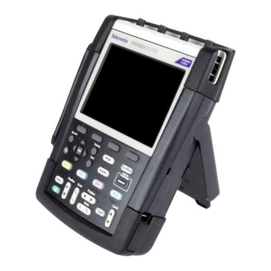
Page 19: Figure 1: Instrument Front Panel
Introduction Figure 1: Instrument front panel The front panel allows you to configure the instrument, access SW version information, display language options, and instrument functions. In this section of the manual, you can review the menus for each button. The buttons are listed in alphabetical order. - Page 20 Introduction Duty Cycle: Positive, Negative mAs (current): Sensitivity (100 μV/A, 1 mV/A, 100 mV/A, 400 mV/A, 1 V/A, 10 V/A, 100 V/A) The RECORDER REPLAY submenu. This submenu provides options for recording measurement data and screen images, and contains the following: Trend Plot: Recorder Run/Stop, Options (Time of Day, From Start), View All, Normal, Exit Recorder Scope Roll Mode: Recorder Run/Stop, Exit Recorder...
- Page 21 Introduction Probe Type: Voltage, Current Attenuation (Voltage): 1:1, 10:1, 100:1, 1000:1, 20:1, 200:1 Sensitivity (Current): 100 μV/A, 1 mV/A, 10 mV/A, 100 mV/A, 400 mV/A, 1 V/A, 10 V/A, 100 V/A Probe Calibration: Start Yes, Start No The INPUT 1 OPTIONS submenu. This submenu allows you to set the polarity and bandwidth parameters and contains the following: Polarity: Normal, Inverted, Variable Bandwidth: Full, 20 kHz (HF reject), 20 MHz...
- Page 22 Introduction The AUTO/MANUAL submenu. This submenu allows you to set the cursors to auto adjust or manual adjust This menu is only available when the rise time or fall time cursor is selected. The 1, 2, 3, 4, M, OFF submenu. This submenu allows you to select to which channel to apply the cursor or to turn the cursor off for a selected channel.
- Page 23 Introduction The INT menu. Select this menu item to capture a screen and setup to internal instrument memory. There is no submenu associated with this menu item. The FILE OPTIONS menu. This menu allows you to do the following: MEMORY: Select from INT (internal instrument memory) or USB (USB memory device).
- Page 24 Introduction Automatic Auto Level: Select from > 15 Hz or > 1 Hz Trigger Conditions: Update (Auto, Normal, Single Shot), Trigger Filter (Off, Noise Reject, HF Reject), NEvent (Off, On) Video on 1 (channel 1 only): Polarity (Positive, Negative), Signal type (PAL, NTSC, PALPIus, SECAM, Non interlaced) Pulse Width on 1 (channel 1 only): Pulses (positive, negative), Condition (<t, >t, =t (±10%), ≠t (±10%), Update (On Trigger, Single Shot)
-
Page 25: Initial Setup
WARNING. Fire can cause personal injury and/or property damage. To prevent risk of fire, do not use any battery but the battery Tektronix shipped with this product. Only use the THSBAT battery pack with this product. THS3000 Series Oscilloscopes User Manual... - Page 26 Use the supplied power cord with the adapter. For a list of available power cords, see the THS3000 Series Oscilloscopes Installation and Safety Instructions that shipped with your instrument. It can be also be found on the Tektronix Web site at www.tektronix.com/manuals.
- Page 27 Introduction Functional Check After you have installed the battery or connected external power, perform this quick functional check to verify that your instrument is operating correctly. See the THS3000 Series Oscilloscopes Installation and Safety Instructions for battery installation and power information. Perform this adjustment to match your probe to the input channel.
-
Page 28: Restore Factory Default Settings
Introduction Figure 2: Rising edge of square wave 10. Adjust the probe as needed. 11. Select Continue and instrument will respond that the calibration is complete and the calibration signal will be removed. 12. Select Close. 13. Repeat steps 3 through 12 on all remaining channels. Restore Factory Default Settings To reset the instrument to the factory default settings, do the following: 1. -
Page 29: Tilt Stand, Hanging Hook, And Kensington® Lock
Introduction Tilt Stand, Hanging Hook, and Kensington® Lock Tilt Stand This instrument has a built-in tilt stand that folds out and folds back into place when not in use. For benchtop use, pull the portion of the tilt stand nearest to the base of the instrument up and away from the instrument until it locks. -
Page 30: Figure 4: How To Use The Hanging Hook Handle
Introduction Hanging Hook To hang the instrument from a cabinet door, separation wall, or ladder rung, you can attach a hook handle (optional accessory). To attach the hook handle, close the tilt stand, screw the hook handle into the back of the instrument, and then hang the instrument where needed. -
Page 31: Figure 5: How To Use The Hanging Strap Handle
Introduction Hanging Strap You can also hang the instrument from a door handle or similar object using the hanging strap handle. To attach the hanging strap to the instrument, thread it through the bars on the top right and left sides of the instrument and secure the ends as shown in the following figure. - Page 32 Introduction THS3000 Series Oscilloscopes User Manual...
-
Page 33: Operating Basics
Operating Basics Input Connections The top panel of the instrument has four safety BNC jack signal inputs. The color at the base of each BNC input corresponds to the color of the related channel button on the front panel. Isolated input architecture allows independent floating measurements with each input. -
Page 34: About Floating Measurements
Operating Basics About Floating Measurements You can use the independently floating isolated inputs to measure signals that are independently floating from each other. The instrument has independently floating isolated inputs. Each input section (1, 2, 3, and 4) has its own signal input and its own reference input. -
Page 35: Figure 8: Common-Reference Input Architecture
Operating Basics Many handheld oscilloscope products have the architecture shown below, which shares a common reference for the oscilloscope channels. (See Figure 8.) With this architecture, all input signals must have the same voltage reference when you take any multi-channel measurements. Figure 8: Common-reference input architecture Most bench-top oscilloscopes share the architecture shown above, but without the insulated case. -
Page 36: Connect Probes And Leads
WARNING. To avoid electric shock, do not use probes that require a ground connection, such as the Tektronix P5200 High Voltage Differential Probe, with the THS3000 Series Oscilloscopes. The P5200 High Voltage Differential Probe requires an instrument with grounded inputs and the TH3000 Series Oscilloscopes have floating inputs (isolated inputs). -
Page 37: Figure 9: Parasitic Capacitance Between Probes, Instrument, And Environment
Operating Basics Attach the Reference If you are using all four of the instrument channels, you must attach the probe reference lead for each channel directly to your circuit. These attachments Leads Correctly are required because the channels are electrically isolated; they do not share a common chassis connection. -
Page 38: Figure 10: Parasitic Capacitance Between Analog And Digital Reference
Operating Basics Parasitic capacitance between analog and digital reference. Parasitic capacitance can occur between the input references mutually. For example, between an analog and digital reference. For this reason, you should connect the references to a system ground or another stable voltage. If the reference of an input is connected to a high speed and/or high voltage signal, you should be aware of parasitic capacitance. -
Page 39: Figure 12: Wrong Connection Of Reference Leads
Operating Basics This is a the wrong way to connect reference leads. Noise that is picked up by reference lead 4 can be transmitted by parasitic capacitance to the analog input amplifier. (See Figure 12.) Figure 12: Wrong connection of reference leads THS3000 Series Oscilloscopes User Manual... -
Page 40: Figure 13: Making Voltage Probe Connections On Four Channels
Operating Basics Make Voltage Probe To make measurements on four channels, connect the yellow voltage probe to the channel 1 input, the blue voltage probe to the channel 2 input, the magenta Connections voltage probe to the channel 3 input, and the green voltage probe to the channel 4 input. -
Page 41: Figure 14: Voltage Probe Connection Using A Ground Spring
Operating Basics Connections With Probe The following images show several different types of probe accessories and their attachments. Accessories Connection using a ground spring. The following image shows a voltage probe connection using a ground spring. WARNING. To avoid electrical shock or fire, do not connect the ground spring to voltages higher than 30 Vrms from earth ground. -
Page 42: Figure 15: Connections Using Hook Tips And Alligator Clip Grounding
Operating Basics Connections Using Hook Tips and Alligator Clip Grounding. Connect the probes as shown in the following image, making sure to reapply the insulation sleeve over the probe tip when the hook tip is not in use to avoid electrical shock. (See Figure 15.) WARNING. -
Page 43: Figure 16: Probe Tip Ground Ring
Operating Basics Connections with a ground lead. The voltage applied to the reference lead is also present on the ground ring near the probe tip. The ground ring is shown here. WARNING. To avoid electrical shock, always use the insulation sleeve or the probe tip when using the probe reference (ground) lead. -
Page 44: Select An Input Channel
Operating Basics Select an Input Channel After you have connected probes to the desired inputs, you will want to select an input channel and set the parameters for that channel. To select a channel, do the following: 1. Press one of the channel buttons to display the associated input menu and to turn the input on. -
Page 45: Adjust The Probe Type Settings
Operating Basics Adjust the Probe Type Settings To obtain correct measurement results, the instrument probe type settings must correspond to the connected probe types. To select the Channel 1 probe setting, do the following: 1. Press the Ch 1 button to display the input menu. 2. -
Page 46: Figure 17: Display With Autoset
Operating Basics If the frequency range is set to 1 Hz and up, the instrument is instructed to analyze low frequency components for automatic triggering. 5. Select Unchanged or Set to DC under Input coupling. Selecting the former retains the coupling setting as it is set in the channel button menu of the active input. -
Page 47: Automatic Measurements
Operating Basics Enable AutoRange™ To enable the AutoRange™ feature, press and hold the Autoset button until AUTORANGE appears in the top right corner of the display screen. The values showing across the bottom of the display screen show range and trigger information. - Page 48 Operating Basics Choose a Frequency To choose a frequency measurement for channel 1, do the following: Measurement for Channel 1. Press the Ch 1 button to turn the input on. 2. Press the Acquire button to view the menu. 3. Select MEASURE. 4.
-
Page 49: Figure 19: Hz And V Peak-Peak As Measurements
Operating Basics The display now shows two measurements and the top left of the screen shows the Hz measurement. The character size will be reduced when more then two readings are on. (See Figure 19.) Figure 19: Hz and V peak-peak as measurements NOTE. -
Page 50: Stop The Display
Operating Basics Stop the Display You can freeze the display (all measurements and waveforms) at any time by pressing the Run/Stop button until STOP appears in red in the top right portion of the display screen and the Run/Stop button is illuminated. (See Figure 20.) Figure 20: Frozen (stopped) display Press the Run/Stop button again to unfreeze the display. -
Page 51: Average, Persistence, And Glitch Capture
Operating Basics Figure 21: Live (running) display Average, Persistence, and Glitch Capture Use the average functions to smooth waveforms by suppressing random or uncorrelated noise in the waveform without loss of bandwidth. Waveform samples with and without smoothing are shown here. (See Table 1.) Smooth a Waveform With To smooth a waveform using averaging, do the following: Averaging... -
Page 52: Table 1: Comparison Of Averaged Versus Nonaveraged Waveforms
Operating Basics 6. Select Normal or Smart average. Normal averaging. In the normal average mode, occasional deviations in a waveform distort the averaged wave shape, and do not show up on screen clearly. When a signal really changes, for instance when you are probing, it takes some time before the new wave shape is stable. -
Page 53: Figure 22: Using Persistence To Observe Dynamic Signals
Operating Basics Figure 22: Using persistence to observe dynamic signals Glitches To capture glitches on a waveform, do the following: 1. Open the ACQUIRE OPTIONS menu. 2. Select Glitch On. 3. Press CLOSE to exit the menu. You can use this function to display events (glitches or other asynchronous waveforms) of 8 ns (due to ADC’s with 125 MS/s sampling speed) or wider, or you can display HF modulated waveforms. -
Page 54: Acquire Waveforms
Operating Basics Suppress High Frequency Turning glitch detect off will suppress the high frequency noise on a waveform. Averaging will suppress the noise even more: Noise 1. Open the ACQUIRE OPTIONS menu. 2. Select Glitch Off. 3. Select Average On to open the Average menu 4. - Page 55 Operating Basics Reverse the Attenuation of You may want to reverse the attenuation of a displayed waveform. For example, a negative-going waveform is displayed as a positive-going waveform which the Displayed Waveform may provide a more meaningful view. An inverted display is identified by an inversed trace identifier ( ) at the right of the waveform, and in the status line below the waveform.
- Page 56 Operating Basics 5. Exit the menu. You will see the channel number and Var in the left bottom portion of the display screen. NOTE. Selecting Variable will turn off cursors and automatic input ranging. Press the Vertical Position buttons to increase or decrease sensitivity. Adjust Bandwidth to You can use bandwidth filters to suppress high frequency noise on waveforms by limiting the working bandwidth to 20 kHz or 20 MHz.
- Page 57 Operating Basics To use a Mathematics function, do the following: 1. Press the Acquire button. 2. Select ACQUIRE OPTIONS. 3. Select Mathematics from the Waveform options. 4. Select a function and then a channel for an A and B source. 5.
- Page 58 Operating Basics Using Mathematics The spectrum function shows the spectral content of the input 1, 2, 3, or 4 waveform(s) in the input trace color. It performs an FFT (Fast Fourier Transform) Function Spectrum (FFT) to transform the amplitude waveform from the time domain into the frequency domain.
-
Page 59: Figure 23: Fft Measurement
Operating Basics 4. Select function FFT and then Source channel and a Window type. 5. Check that FFT shows at the top right of the display screen that appears. (See Figure 23.) If LOW AMPL shows, a spectrum measurement cannot be done because the waveform amplitude is too low. - Page 60 Operating Basics 8. Set the vertical amplitude scale to logarithmic (LOG) or linear (LINEAR) by pressing the function button under that menu item. 9. You can turn the FFT display on and off (toggle function) by selecting ON or OFF under the FFT menu item. Compare Waveforms You can display a fixed reference waveform with the actual waveform for comparison.
- Page 61 Operating Basics 3. Select Reference from the Waveform options. 4. Select On under Reference to display the reference waveform. The reference waveform can be: the last used reference waveform (if not available, no reference waveform will be shown) the envelope waveform (if the persistence function Envelope is on) 5.
-
Page 62: Pass-Fail Testing
Operating Basics on the display is 0.04 × range/div. 1 horizontal pixel on the display is 0.0333 × range/div. Table 2: Pixel colors description Pixel color Description black pixels basic waveform gray pixels ± 2 pixels envelope Pass-Fail Testing You can use a reference waveform as a test template for the actual waveform. If at least one sample of a waveform is outside the test template, the failed or passed scope screen will be stored. -
Page 63: Recorder Functions
Recorder Functions This chapter provides a step-by-step introduction to the recorder functions of the instrument. The introduction gives examples to show how to use the menus and perform basic operations. Access the RECORDER REPLAY.. menu by first pressing the Acquire button. From the RECORDER REPLAY.. -
Page 64: Figure 25: Trendplot™ Measurement
Recorder Functions following display shows a trend plot with cursors enabled for measurement. (See Figure 25.) NOTE. Read more about analyzing waveform using cursors. (See page 54.) 8. To turn off the TrendPlot™ display, select EXIT RECORDER. Figure 25: TrendPlot™ measurement The instrument continuously records the digital readings of the measurements and displays these as a graph. -
Page 65: Record Waveforms In Deep Memory (Scope Roll Mode)
Recorder Functions Record Waveforms In Deep Memory (Scope Roll Mode) The SCOPE ROLL MODE function logs a long waveform of each active input. Use this function to monitor waveforms such as motion control signals or the power-on event of an Uninterruptable Power Supply (UPS). During recording, fast transients are captured. - Page 66 Recorder Functions Use Single Sweep Mode You can use the recorder Single Sweep mode to automatically stop recording when the deep memory is full. To activate single sweep mode, do the following: 1. Set up the instrument as in the previous procedure. (See page 49, Start Scope Roll Mode.) 2.
- Page 67 Recorder Functions Samples are continuously saved in deep memory during recording. The last twelve recorded divisions are displayed on the screen. Use View All to display the full memory contents. NOTE. You can learn more about Single Shot triggering. (See page 66.) THS3000 Series Oscilloscopes User Manual...
-
Page 68: Analyze Waveforms
Analyze Waveforms Analyze Waveforms You can use the Replay, Zoom, and Cursors analysis functions to perform detailed waveform analyses. These functions can be used with one or more of the primary functions: Acquire, TrendPlot™, or Data Log Replay. It is possible to combine two or three analysis functions. A typical application using these functions is: First replay the last screens to find the screen of special interest. -
Page 69: Use Zoom
Analyze Waveforms Replay All Acquired You can also replay all of the stored screens in sequence, from oldest to newest. To replay all acquired screens, do the following: Screens 1. Press the Acquire button. 2. Select the RECORDER REPLAY.. menu option. 3. -
Page 70: Use Cursors
Analyze Waveforms key) to move the waveform to the right or left of the screen. The position bar shows the position of the zoomed part in relation to the total waveform. Observe that the bottom of the waveform area displays the zoom ratio, position bar, and time/div. -
Page 71: Figure 28: Voltage Measurement With Horizontal Cursors
Analyze Waveforms : Rise time cursor : Fall time cursor 3. Press the function key under the MOVE menu item to highlight the upper cursor (if it is not already highlighted). 4. Use the up and down arrow keys to position the upper cursor. 5. - Page 72 Analyze Waveforms Use Vertical Cursors on a To use the cursors for a time measurement (T, 1/T), for a mVs-mAs-mWs measurement, or for an RMS measurement of the trace section between the Waveform cursors, do the following: 1. Press the Cursors button 2.
-
Page 73: Figure 29: Time Measurement With Vertical Cursors
Analyze Waveforms 7. Use the left and right arrow keys to position the right cursor. NOTE. Even when the key labels are not displayed at the bottom of the screen, you still can use the arrow keys. This allows full control of both cursors while having a full screen view. - Page 74 Analyze Waveforms 3. If MANUAL is not already highlighted, press the function key under the AUTO/MANUAL menu item to highlight MANUAL. NOTE. Select AUTO to automatically complete steps 4 through 7. 4. Press the function key under the MOVE menu item to highlight the upper cursor (if it is not already highlighted).
-
Page 75: Figure 30: Risetime Measurement Using Cursors
Analyze Waveforms Figure 30: Risetime measurement using cursors THS3000 Series Oscilloscopes User Manual... -
Page 76: Trigger Functions
Trigger Functions Trigger Functions About this Chapter This chapter provides an introduction to the trigger functions of the instrument. Triggering tells the instrument when to begin displaying the waveform. You can use fully automatic triggering, take control of one or more main trigger functions, or you can use dedicated trigger functions to capture special waveforms. -
Page 77: Table 3: Trigger Types
Trigger Functions Trigger Filter Trigger filtering determines what part of the signal is passed to the trigger circuit. Edge triggering can use both available filter types: Noise Reject and HF Reject. Following are some typical trigger applications: Use the AutoRange™ function to have full automatic triggering and stable display of most waveforms. - Page 78 Trigger Functions Table 3: Trigger types (cont.) Trigger type Trigger conditions Video Trigger on specified fields or lines of a composite video signal. Only composite signal formats are supported. Trigger on NTSC, PAL, PALPIus, SECAM, or non interlaced signals. Rise/Fall time Trigger on rise and fall times.
-
Page 79: Figure 31: Screen With All Trigger Information
Trigger Functions Figure 31: Screen with all trigger information In the following screen, observe the trigger icon that indicates the trigger position, trigger level, and slope. At the bottom of the screen the trigger parameters are displayed. For example, means that channel 1 is used as the trigger source with a positive slope. When a valid trigger signal is found, the trigger button will be lit and the trigger parameters appear in white. -
Page 80: Figure 32: Trigger Delay Or Pretrigger View
Trigger Functions When a valid trigger signal is found, the trigger button will be lit and the trigger parameters appear in white. When no trigger is found, the trigger parameters appear in gray, and the button backlight will be off. The following image shows an example of a trigger delay of 500 ms (top) and an example of a pretrigger view of 8 divisions (bottom). - Page 81 Trigger Functions 5. Exit the menu. Trigger on Edges If the signal is unstable, complex, or has a very low frequency, use edge triggering to obtain full manual trigger control. To trigger on the rising edge of the Ch 1 waveform, do the following: 1.
- Page 82 Trigger Functions Trigger on noisy waveforms. To reduce jitter on the screen when triggering on noisy waveforms, you can use a trigger filter, as follows: 1. Press the Trigger button. 2. Select TRIGGER OPTIONS. 3. Select Trigger Conditions. 4. Select a trigger filter: Noise Reject: an increased trigger gap will be applied HF Reject: HF noise on the (internal) trigger signal will be suppressed NOTE.
-
Page 83: Figure 33: Making A Single Shot Measurement
Trigger Functions Figure 33: Making a single shot measurement NOTE. The instrument stores all single shots in the replay memory. Use the Replay function to look at all the stored single shots. (See page 52, Use Replay.) N-Event trigger. N-Event triggering enables you to create a stable picture of n-event burst waveforms. -
Page 84: Figure 34: N-Event Triggering
Trigger Functions 5. Press the function button under the NEVENT menu item and then use the right and left arrow keys to select the number of events. 6. Press the Trigger Level buttons to adjust the trigger level. This screen shows an N-Event trigger in which N=3. (See Figure 34.) Figure 34: N-Event triggering Trigger On Video Signals To trigger on a video signal, first select the standard of the video signal you are... -
Page 85: Figure 35: Trigger On Ntsc Video Signal Field 1
Trigger Functions 5. Adjust trigger video settings as needed in the menu that appears. For example, to trigger on either the first half of a frame (Field 1, odd) or the second half of a frame (Field 2, even), select that field from the FIELD menu and the signal part of that field will be displayed. -
Page 86: Figure 36: Pulse Width Triggering
Trigger Functions Detect narrow pulses. To set the instrument to trigger on narrow positive pulses shorter than 5 ms, do the following: 1. Press the Trigger button. 2. Select TRIGGER OPTIONS. 3. Select Pulse Width on and press the Enter button. 4. -
Page 87: Save And Recall
Save and Recall Save and Recall The Save and Recall functions, both accessed from the Save button menu, allow you to do the following: Maximum USB memory size supported is 2 GB Save screens and setups to internal memory and recall them again from memory. - Page 88 Save and Recall Save Screens with To save a screen + setup, do the following: Associated Setups 1. Press the Save button. Once the menu appears, the display screen will be frozen. 2. Select SAVE..3. Select the target memory: INT (internal memory) or USB (USB device). Observe the number of available and used memory locations.
- Page 89 Save and Recall What to do when all memories are in use. If no free memory locations are available, a message pops up that proposes to you to overwrite the oldest data set. Do one of the following: If you do not want to overwrite the oldest data set, press the function 3 button (NO).
- Page 90 Save and Recall 4. Use the down arrow key to highlight DELETE. 5. Press the right arrow to move to the file name list, and then use the down arrow key to highlight the file you want to delete. 6. Press the Enter button. 7.
- Page 91 Save and Recall 4. Use the up or down arrow key to highlight DATA and press the Enter button. 5. Press the up and down arrow keys to select the file you want to recall and then select VIEW. 6. A message will appear asking if you want to continue to view mode, as data on the display screen will be lost.
- Page 92 Save and Recall 6. A message will appear asking if you want to continue to view mode, as data on the display screen will be lost. Select YES to recall the selected setup. 7. Observe that the recalled setup is displayed and that STOP appears on the screen.
- Page 93 Save and Recall Rename Stored Screens To rename a stored screen + setup file, do the following: and Setup Files 1. Press the Save button. Once the menu appears, the display screen will be frozen. 2. Select FILE OPTIONS..3. Select the target memory: INT (internal memory) or USB (USB device). 4.
- Page 94 Save and Recall Copy or Move Stored You can copy or move a file from internal memory to a USB device or from a USB device to internal memory by doing the following: Screens and Setup Files 1. Press the Save button. Once the menu appears, the display screen will be frozen.
-
Page 95: Troubleshooting
Troubleshooting Troubleshooting What To Do If The The batteries may be empty. Check the battery symbol at the top right of the screen. A symbol indicates that the batteries are empty and must be Instrument Shuts Down charged. Connect the power adapter. After a Short Time The instrument is still on but the Display Auto-OFF timer is still active. - Page 96 Troubleshooting THS3000 Series Oscilloscopes User Manual...
-
Page 97: Appendix A: Specifications
Appendix A: Specifications Introduction Performance Tektronix guarantees the properties expressed in numerical values with the stated tolerance. Specified non-tolerance numerical values indicate those that could be Characteristics nominally expected from the mean of a range of identical oscilloscopes. The oscilloscope meets the specified accuracy 30 minutes and two complete acquisitions after power on. -
Page 98: Table 6: Oscilloscope Inputs
Characteristic Description Isolated Vertical Inputs (Ch 1, 2, 3, and 4) Input coupling AC, DC Bandwidth, DC coupled THS3024 200 MHz (–3 dB) THS3014 100 MHz (–3 dB) Lower frequency limit, AC coupled with 10:1 probe <2 Hz (–3 dB) direct (1:1) <5 Hz (–3 dB) - Page 99 Minimum time base speed (Scope Roll Mode) 2 min/div <4 h/DIV> Time base accuracy ±(100 ppm + 0.04 div) Maximum real time sampling rate THS3024 One channel up to 5 GS/s Two channels up to 2.5 GS/s Three to four channels up to 1.25 GS/s...
- Page 100 Trigger N-cycle range 2–99 cycles Trigger sensitivity DC to 5 MHz at >5 mV/div 0.5 divisions DC to 5 MHz at 2 mV/div and 5 mV/div 1 division THS3024 200 MHz 1 division 250 MHz 2 divisions THS3014 100 MHz...
- Page 101 Appendix A: Specifications Table 6: Oscilloscope Inputs (cont.) Characteristic Description Scan rates 14–22 kHz 19–33 kHz 31–65 kHz Pulse Width Trigger Screen update On Trigger, Single Shot Trigger conditions <T, >T, =T (±10%), ≠T(±10%) Source Polarity Positive or negative pulse Sensitivity same as edge trigger Level...
-
Page 102: Automatic Measurements
Appendix A: Specifications Automatic Measurements The accuracy of all measurements is within ± (% of measurement + number of counts) from 18 °C to 28 °C. Add 0.1x (specific accuracy) for each °C below 18 °C or above 28 °C. At least 1.5 waveform periods must be visible on the screen. Table 7: Automatic measurement specifications Characteristic Description... - Page 103 Appendix A: Specifications Table 7: Automatic measurement specifications (cont.) Characteristic Description AC coupled, high frequencies 60 Hz to 20 kHz ±(2.5 % + 15 counts) 20 kHz to 1 MHz ±(5 % + 20 counts) 1 MHz to 25 MHz ±(10 % + 20 counts) For higher frequencies, the frequency roll off of the instrument starts to affect accuracy.
- Page 104 Appendix A: Specifications Table 7: Automatic measurement specifications (cont.) Characteristic Description Peak Modes Max peak, min peak, or peak-to-peak Maximum voltage with 10:1 probe 1000 V direct (1:1) 300 V Maximum resolution with 10:1 probe 10 mV 1 mV direct (1:1) Full scale measurement 800 counts Accuracy...
-
Page 105: Recorder Specifications
Appendix A: Specifications Recorder Specifications Table 8: Recorder Characteristic Description TrendPlot (Channel 1, 2, 3, 4) Chart recorder mode that plots a graph of min and max values of oscilloscope measurements (four max) over time. Measurement speed >5 measurements/s Time/div 5 s/div to 30 min/div ≥18000 points Record size (min, max, average) -
Page 106: Miscellaneous Specifications
Appendix A: Specifications Table 9: Zoom, Data Log, and Cursors (cont.) Characteristic Description Markers automatic markers at cross points Measurements value at cursor 1 value at cursor 2 difference between values at cursor 1 and 2 time between cursors RMS between cursors Time of Day (Recorder modes) Time from Start (Recorder modes) Rise Time, fall time... -
Page 107: Table 12: Probe Calibration Output Signal
Appendix A: Specifications Table 11: Power (cont.) Characteristic Description Power adapter 119-7900-xx Line cord options • Option A0 North American line cord • Option A1 European line cord • Option A2 United Kingdom line cord • Option A3 Australian line cord •... -
Page 108: Table 14: Interface Ports
Appendix A: Specifications Table 14: Interface Ports Port Description USB-host port Directly connects to external flash memory drive for storage of waveform data, measurement results, instrument settings and screen copies. Mini-USB-B port Connects to a PC for screen images, settings, and data transfer using OpenChoice™ software. Note: Remote control and data transfer via the mini-USB port is not possible when saving or recalling data through the USB-host port. -
Page 109: Safety Specifications
Appendix A: Specifications Table 16: Environmental (cont.) Characteristic Description Electromagnetic compatibility (EMC) Emission and immunity EN 61326-1:2006, EN 61326-2-1:2006 Enclosure protection IP41, ref: IEC60529 Safety Specifications Designed for 1000 V measurement category II, 600 V measurement category III, Pollution Degree 2, per: IEC/EN 61010-1: 2001 Pollution Degree 2 (According to CE marking) UL 61010-1:2004 CAN/CSA-C22.2 No. -
Page 110: Figure 37: Input Voltage Versus Frequency
Appendix A: Specifications Figure 37: Input voltage versus frequency NOTE. Measurement Category II refers to circuits connected to mains socket outlets and similar points in the mains installation. Measurement Category III refers to distribution level and fixed installation circuits inside a building. Figure 38: Maximum voltage between oscilloscope references, and between oscilloscope references and earth ground THS3000 Series Oscilloscopes User Manual... -
Page 111: Probe Specifications
Appendix A: Specifications Probe Specifications Table 18: THP0301 Voltage Probe Characteristic Description Attenuation 10:1 Bandwidth DC to 300 MHz (–3 dB) Rise time 0.9 ns Compensation range 10 pF–22 pF Maximum tip input voltage 300 V CAT III Maximum reference lead voltage to ground 300 V CAT III NOTE. - Page 112 Appendix A: Specifications THS3000 Series Oscilloscopes User Manual...
-
Page 113: Appendix B: Connect The Instrument To A Computer
You can connect your instrument directly to a computer through a USB port and a software application, such as Tektronix OpenChoice® Desktop. Connecting to a PC will allow you to collect screen images and let the PC analyze your data. -
Page 114: Usb Ports
Appendix B: Connect the Instrument to a Computer USB Ports The instrument has two USB ports: Maximum USB memory size supported is 2 GB A USB-host port to connect an external USB memory device for data storage. A mini-USB-B port which allows you to connect the instrument to a PC or notebook for remote control and data transfer under computer control. -
Page 115: Install Usb Drivers
PC. The oscilloscope does not need to be connected to the PC during the initial USB driver installation. To install the USB drivers, use the Tektronix InstallShield Wizard that is included on the OpenChoice CD provided with the instrument. -
Page 116: Confirm Oscilloscope And Pc Communication
Com 1..4). In this situation, the COM port number can be changed manually. To manually assign a different COM port number, right click‘Tektronix THS3024 USB Serial Port COM(23)’ and select properties. From the Properties menu, select the Port Settings tab, and click Advanced… to change the port number. - Page 117 After installing the software, when you first open the application, click on SELECT INSTRUMENT, and then choose ASRLxx::INSTR, which should match the COM number of the port assigned during the USB driver installation. For more information about OpenChoice™, visit the Tektronix Web site at www.tektronix.com. THS3000 Series Oscilloscopes User Manual...
- Page 118 Appendix B: Connect the Instrument to a Computer THS3000 Series Oscilloscopes User Manual...
-
Page 119: Appendix C: Probe Compensation And Compatible Maximum Voltages
Appendix C: Probe Compensation and Compatible Maximum Voltages Compensate Voltage Probes To meet full user specifications, you need to adjust the voltage probes for optimal response. The compensation consists of a high frequency adjustment and a DC compensation for 10:1 probes and 100:1 probes. The probe compensation matches the probe to the input channel. - Page 120 Appendix C: Probe Compensation and Compatible Maximum Voltages 11. Select Continue and instrument will respond that the compensation is complete and the compensation signal will be removed. Automatic DC compensation is only possible for 10:1 voltage probes. NOTE. During compensation you should not touch the probe. 12.
-
Page 121: Compatible Probe Maximum Voltages
Appendix C: Probe Compensation and Compatible Maximum Voltages Compatible Probe Maximum Voltages WARNING. Do not exceed the Measurement Category (CAT), voltage, altitude, or temperature rating of the lowest rated individual component of a product, probe, or accessory. Table 19: Compatible probe maximum voltages Passive probes THP0301 P5150... - Page 122 Appendix C: Probe Compensation and Compatible Maximum Voltages THS3000 Series Oscilloscopes User Manual...
-
Page 123: Appendix D: Battery Pack
Appendix D: Battery Pack Save Battery Life When operated on the battery, this instrument conserves power by shutting itself down. If you have not pressed a button for at least 30 minutes, the instrument turns itself off automatically. Automatic power shutdown will not occur if TrendPlot™ or Scope Roll Mode is on, but the backlight will dim. -
Page 124: Charge The Batteries
Appendix D: Battery Pack 5. You can also adjust the Display Auto-OFF time now. 6. Exit the menu. The instrument (or display) will be turned off after the selected time is elapsed. To turn on the display again, do one of the following: Press any key. - Page 125 Appendix D: Battery Pack To charge the batteries and power the instrument, connect the power adapter as shown below. To charge the batteries more quickly, turn off the instrument. CAUTION. To avoid overheating of the batteries during charging, do not exceed the allowable ambient temperature given in the specifications.
- Page 126 Appendix D: Battery Pack THS3000 Series Oscilloscopes User Manual...
-
Page 127: Appendix E: Maintenance And Cleaning
Appendix E: Maintenance and Cleaning Maintaining the Instrument WARNING. • Have an approved technician repair the product. • Use only specified replacement parts. • Before carrying out any maintenance, carefully read the safety information at the beginning of this manual. Cleaning WARNING. - Page 128 Appendix E: Maintenance and Cleaning THS3000 Series Oscilloscopes User Manual...
-
Page 129: Index
Index Button Display Acquire, 3 auto shut-off options, 8 AC, DC coupling, 28, 61 Autoset, 4 Accessories Ch 1-4, 4 where to find a list of, 2 Cursors, 5 Acquire, 3 Factory default settings, 8, 12 Enter, 6 Adjusting Features Level, 6 contrast, 9 list of general, 1... - Page 130 Index Memory Recorder Time viewing files in, 7 changing options, 47 setting, 8 Menu displaying data, 47 TrendPlot™ Acquire, 3 functions, 47 analyzing a record, 52 AutoRange, 4 menu, 47 plot measurements, 47 Autoset, 4 plot measurements, 47 Trigger Ch 1-4, 4 start or stop using button, 7 Cursors, 5...
Need help?
Do you have a question about the THS3024 and is the answer not in the manual?
Questions and answers