Table of Contents
Advertisement
Quick Links
The Wegener Model DTV720 Transport Stream Multiplexor receives up to two input ASI MPEG transport streams and two ATSC
8VSB broadcast signals and provides an output ASI stream (and optional DHEI stream) for connection to cable system transmission
equipment. This guide provides information for setting up and operating the DTV720. Additional information may be found on the
Wegener web site at
www.wegener.com/
In addition to this guide, your box should include:
1. DTV720 Transport Stream Multiplexor
2. Power cord
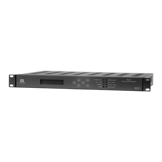
Front- and Rear-Panel Views
Connector/Pin-out Information
Ref
Connector Designation
1&2
RF In
3&4
ASI In 1 & ASI In 2
5&6
ASI Out 1 & ASI Out 2
7
Ethernet
8
Serial I/O
9
Status Relays
10
DHEI
11
115/230 VAC
Status Relays
Signals (Ref 9)
Pin
Signal Name
#
9
Alarm NC
4
Alarm COM
8
Warning NC
3
Warning COM
6
Warning NO
1
Not used
7
Alarm NO
2
Not used
800043-02 Rev. A
DTV720 Installation Quick Start Guide
3. UL safety sheet
Rear Panel Connector Descriptions
Type
Signal Name
F (female)
RF In
BNC
ASI In
BNC
ASI Out 1 & ASI Out 2
RJ-45 jack
Ethernet_In & Out
DB-9
For Factory Use Only
DB-9
Alarm Contact Closure
DB-15
DHEI Output
IEC receptacle
AC Line In
LED
Description
OPTION
For Use with Optional Module 1
MOD 1
ASI 1
ON - ASI input sync present on ASI 1
LOCK
OFF – Loss of ASI input, PAT, or PMT.
ON – Warning conditions
WARNING
OFF – No warnings
ON – Alarm conditions
ALARM
OFF – No alarms
LED Indicator Descriptions
LED
OPTION
MOD 2
ASI 2
LOCK
ASI OUT
LOCK
LAN
ACTIVITY
Page 1 of 6
Description
Off-air signal from antenna or other RF source
ASI from IRD or other source
To QAM Modulator or ASI Mux
To LAN – for WEB Control
For Factory Use Only
To Alarm Monitoring
To QAM Modulator or ASI Mux
To AC Power Outlet
Description
For Use with Optional Module 2
ON - ASI input sync present on ASI 2
OFF – Loss of ASI input, PAT, or PMT.
ON – ASI output active
OFF – No ASI output
ON – Ethernet data to the unit.
July 21, 2004
Advertisement
Table of Contents

Related Manuals for Wegener DTV720


Summary of Contents for Wegener DTV720
- Page 1 DTV720 Installation Quick Start Guide The Wegener Model DTV720 Transport Stream Multiplexor receives up to two input ASI MPEG transport streams and two ATSC 8VSB broadcast signals and provides an output ASI stream (and optional DHEI stream) for connection to cable system transmission equipment.
- Page 2 IRT Mode WARNING: Do not select IRT mode unless using the DTV720 with Motorola or General Instruments equipment. Using IRT mode in other situations may have unexpected results. With systems using the Motorola IRT product, certain additional elements must be included in the output transport stream. In such systems, be sure to enable the DTV 720’s IRT Mode by selecting IRT Mode ON from the web browser interface or front...
- Page 3 Environmental Operating Conditions & Physical Specifications Indoor Altitude Up to 2000 meters Temperature Range C to +50 80% for temperatures up to 31 C decreasing linearly to 50% relative Relative Humidity (max.) humidity at 40 Weight 10.6 pounds or 4.81 kilograms Dimensions (H x W x D) 3.5”x 19”x 10.5”...
- Page 4 Main-level Screens Second-level Screens Input Setup ASI Input 1 A S I I n p u t 1 I n p u t S e t u p . . . Press ENT and use the 5 5 or 6 6 keys to select <ON>...
- Page 5 LAN Connection – Connect the DTV720 Ethernet connection to the LAN using a normal RJ-45 cable (8 pins). Set the DTV720 IP Address, Netmask, and Gateway as directed by your network administrator. Use any PC on the LAN to connect to the DTV720 using the web browser instructions below.
- Page 6 Desktop Installation To set up the DTV720 in a desktop environment, place it on a flat surface where it will not be subject to being hit or pushed, and will not have anything spilled or dropped on it. Also, the cables connected to the unit should be routed so they are not hit or pulled, which might cause damage to the connectors or to the unit itself.
Need help?
Do you have a question about the DTV720 and is the answer not in the manual?
Questions and answers