Table of Contents
Advertisement
Table of Contents
1. Packaged content ................................................................................................................... 2
2. Technical features ................................................................................................................. 2
3. Description ............................................................................................................................ 3
3.1. Presentation of the MPZ ............................................................................................ 3
3.2. Description of components ......................................................................................... 4
4. Installation ............................................................................................................................. 5
4.1. Integration in a fuse box ............................................................................................ 5
4.2. Electrical connection .................................................................................................. 5
5. Configuration ........................................................................................................................ 7
5.1. Piezoelectric RGB markers ......................................................................................... 8
5.2. Mode of operation .................................................................................................... 10
5.3. Time out ................................................................................................................... 11
6. Operation ............................................................................................................................. 12
6.1. Start-up ..................................................................................................................... 12
6.2. Use ........................................................................................................................... 12
6.3. RGB LED command ................................................................................................ 13
6.4. Multi-function module indicator ............................................................................... 15
A. Declaration of Conformity ............................................................................................... 16
Read all of this leaflet carefully before installing, operating or using this prod-
uct.
MPNT0255 v1.1 (10/03/2015)
Technical instructions
Reference: SF10M070 / PF10M070
MPZ
smart controller for
piezoelectric switch
Advertisement
Table of Contents

Related Manuals for ccei MPZ


Summary of Contents for ccei MPZ
-
Page 1: Table Of Contents
Table of Contents 1. Packaged content ........................2 2. Technical features ......................... 2 3. Description ..........................3 3.1. Presentation of the MPZ .................... 3 3.2. Description of components ..................4 4. Installation ..........................5 4.1. Integration in a fuse box .................... 5 4.2. -
Page 2: Packaged Content
1. Packaged content • 1 modular smart controller MPZ pre-equipped with – 1 6-point pluggable connector for the connection of the piezoelectric button – 1 6-point pluggable connector for the connection of the power and 2 dry contact output points •... -
Page 3: Description
Furthermore, if it is used with a illuminated piezoelectric switch (monochrome or RGB), the lighting (or the colour) of the button is different according to the status of the 2 output points of the MPZ and therefore makes its status known. Marker lighting is also configurable, so that the switch can be detected. -
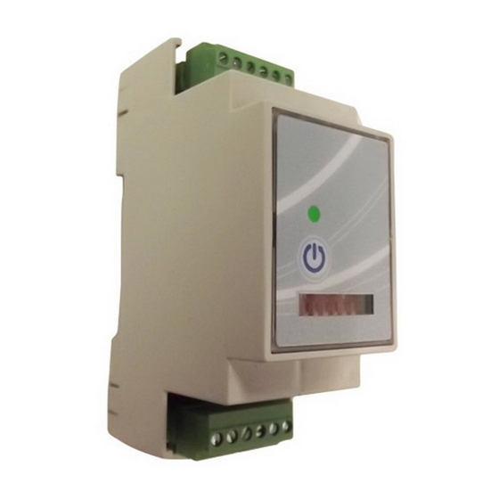
Page 4: Description Of Components
Technical instructions v1.1 3.2. Description of components Multi-function indicator Command/programming key Configuration switches www.ccei.fr... -
Page 5: Installation
4. Installation 4.1. Integration in a fuse box The smart controller for piezoelectric switch MPZ must be installed on a standard DIN rail (OMEGA rail) in a fuse box. It cannot be used as it is. The module has a system which enables it to be automatically clipped onto the rail;... - Page 6 Technical instructions v1.1 www.ccei.fr...
-
Page 7: Configuration
Place the screwdriver as indicated on the photo below on the right of the front panel to unclip it and display the configuration switches; The configuration switches will enable the smart controller for piezoelectric switch MPZ to be placed in the desired operating mode. A flat screwdriver is needed to activate the switches. Each switch may only be in two positions;... -
Page 8: Piezoelectric Rgb Markers
It is possible to activate the "marker" mode. In activated marker mode, when the smart controller for piezoelectric switch MPZ is in an initial position (Seq. 1 of table 5.2, i.e. considered to be off), the RGB lighting of the piezoelectric button is activated to allow the button to be detected. There is a choice of several marker modes;... - Page 9 (when active) gramming) Marker deacti- fixed vated Regular white fixed Green flashes Regular white flashing Yellow flashes Rainbow: per- manent colour flashing Blue gradient White fade out in fixed Magenta a loop White fade out in flashing Cyan a loop www.ccei.fr...
-
Page 10: Mode Of Operation
Technical instructions v1.1 5.2. Mode of operation Switches No. 1 and No. 2 allow the operating mode of the smart controller for piezoelectric switch MPZ to be selected; No. 1 No. 2 Mode Seq. 1 Seq. 2 Seq. 3 Seq. 4... -
Page 11: Time Out
Switch No. 3 allows the time delay mode to be activated or not. In time delay mode, the smart controller for piezoelectric switch MPZ will return to the initial position (Seq. 1 of table 5.2) after the time out duration, which may in turn be selected using switches No. 4 to No. 6;... -
Page 12: Operation
After configuring the desired marker and operating modes, you can power up the installation. As soon as it is powered up, the smart controller for piezoelectric switch MPZ must switch on. A colour gradient is then seen on the RGB lighting of the piezoelectric button (if available), followed by a reminder of the marker operating mode (see 5.1 - column 6) by four flashes. -
Page 13: Rgb Led Command
Green (fixed or flashing according to the mode PZ2 output active see 5.1) Cyan (Blue+Green) PZ1 and PZ2 output points active If you want to change colours, you can cross the R/G/B thread in the output of the smart controller for piezoelectric switch MPZ. www.ccei.fr... - Page 14 PZ1 PZ2 PZ1 PZ2 BLUE (fixed or flashing according to the mode see 5.1) PZ1 PZ2 GREEN (fixed or flashing according to the mode see 5.1) PZ1 PZ2 CYAN (BLUE+GREEN) (fixed or flashing ac- cording to the mode see 5.1) www.ccei.fr...
-
Page 15: Multi-Function Module Indicator
Technical instructions v1.1 6.4. Multi-function module indicator The multi-function indicator, present on the front side of the smart controller for piezoelectric switch MPZ allows its status to be displayed according to the following table: Status of the indicator Meaning Switched off No electrical supply. -
Page 16: Declaration Of Conformity
Technical instructions v1.1 A. Declaration of Conformity The Company Bleu Electrique SAS (FR47403521693) declares that the product MPZ satisfies the safety and electromagnetic compatibili- ty requirements of European directives 2006/95/EC and 2004/108/EC. Emmanuel Baret Marseille, 10/03/2015 Distributor's stamp Date of Sale: ..... . . Serial No: ......
Need help?
Do you have a question about the MPZ and is the answer not in the manual?
Questions and answers