Table of Contents
Advertisement
Quick Links
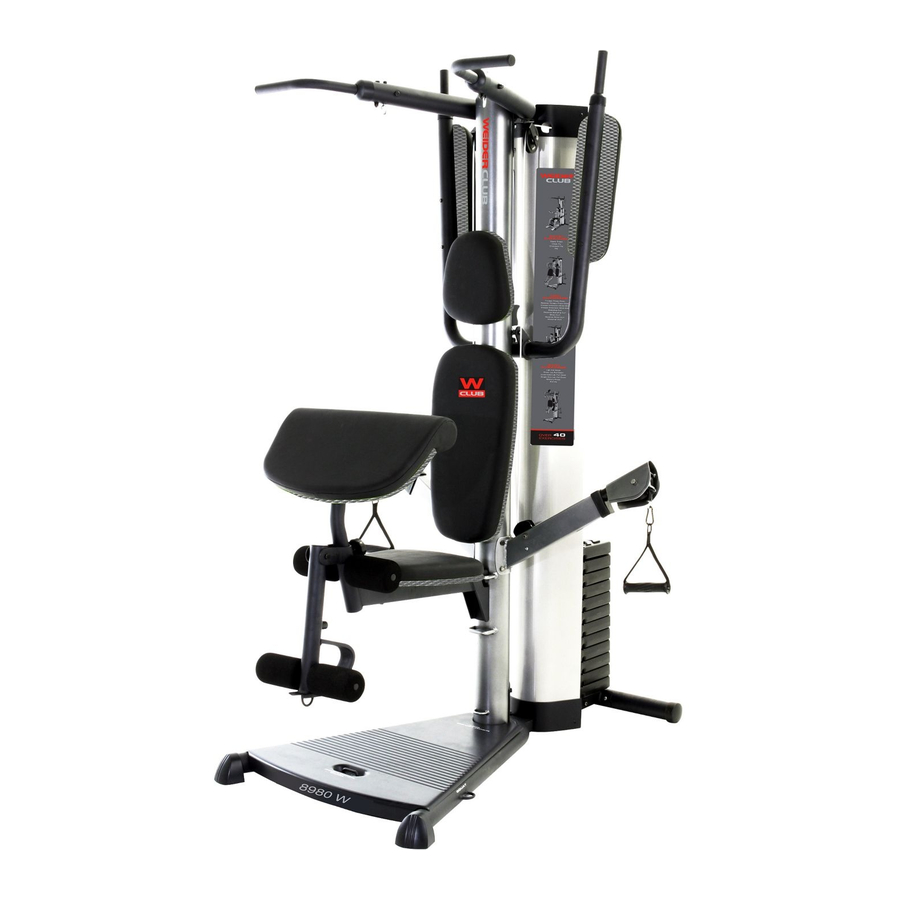
Model No. WEANSY1978.0
Serial No.
Write the serial number in the
space above for reference.
Serial Number Decal (under seat)
QUESTIONS?
If you have questions, or if there
are missing or damaged parts,
please contact the establish-
ment where you purchased this
product.
CAUTION
Read all precautions and instruc-
tions in this manual before using
this equipment. Save this manual
for future reference.
All manuals and user guides at all-guides.com
USERʼS MANUAL
Advertisement
Table of Contents

Related Manuals for Weider 8980 I


Summary of Contents for Weider 8980 I
- Page 1 All manuals and user guides at all-guides.com Model No. WEANSY1978.0 Serial No. USERʼS MANUAL Write the serial number in the space above for reference. Serial Number Decal (under seat) QUESTIONS? If you have questions, or if there are missing or damaged parts, please contact the establish- ment where you purchased this product.
-
Page 2: Table Of Contents
Note: The decal(s) may fingers clear of not be shown at actual size. this area. This decal is placed on both sides of the upright and on the pivot frame. WEIDER is a registered trademark of ICON IP, Inc. -
Page 3: Important Precautions
All manuals and user guides at all-guides.com IMPORTANT PRECAUTIONS WARNING: To reduce the risk of serious injury, read all important precautions and instructions in this manual and all warnings on your weight system before using your weight sys- tem. ICON assumes no responsibility for personal injury or property damage sustained by or through the use of this product. -
Page 4: Before You Begin
All manuals and user guides at all-guides.com BEFORE YOU BEGIN Thank you for selecting the versatile WEIDER 8980 I ing this manual, please see the front cover of this man- ® weight system. The weight system offers a selection of ual. -
Page 5: Part Identification Chart
All manuals and user guides at all-guides.com PART IDENTIFICATION CHART Refer to the drawings below to identify small parts used in assembly. The number in parentheses by each draw- ing is the key number of the part, from the PART LIST near the end of this manual. Note: Some small parts may have been preattached. -
Page 6: Assembly
All manuals and user guides at all-guides.com ASSEMBLY • For help identifying small parts, use the PART Make Assembly Easier IDENTIFICATION CHART on page 5. Everything in this manual is designed to ensure • As you assemble the weight system, make sure that the weight system can be assembled suc- all parts are oriented as shown in the drawings. - Page 7 All manuals and user guides at all-guides.com Frame Assembly Before beginning assembly, make sure you understand the information on page 6. Insert four M8 x 63mm Carriage Bolts (87) up through the Base (1). Note: It may be helpful to place a piece of tape over the bolt heads to hold them in place.
- Page 8 All manuals and user guides at all-guides.com 3. Attach the Front Leg (7) to the Base (1) with the two M8 x 63mm Carriage Bolts (87) and two M8 Locknuts (58). Do not tighten the Locknuts yet. Upward Attach the Leg Bumper (60) to the Front Leg (7) with an M4 x 20mm Self-tapping Screw (69) and an M4 Washer (33).
- Page 9 All manuals and user guides at all-guides.com 6. Orient the Top Frame (4) with the welded support on the bottom. 59 76 Attach the Top Frame (4) to the Upright (3) with two M8 x 65mm Bolts (68), two M8 Washers (59), and two M8 Locknuts (58).
- Page 10 All manuals and user guides at all-guides.com 8. Attach the Shroud (17) to the Top Frame (4) with two M6 x 16mm Screws (62) and two M6 Washers (82). Do not tighten the Screws yet. Attach the Shroud (17) to the brackets on the Stabilizer (2) with two M6 x 16mm Screws (62) and two M6 Washers (82).
- Page 11 All manuals and user guides at all-guides.com 11. Grease an M10 x 51mm Bolt (66). Attach a Cable Pivot (39) to the Left Arm (10) with the Bolt and Grease an M10 Locknut (56). Do not overtighten the Locknut; the Cable Pivot must pivot easily. Attach a Handle (11) to the Left Arm (10) with two M10 x 25mm Button Screws (77) and two M10 Washers (57).
- Page 12 All manuals and user guides at all-guides.com 14. Route the Arm Cable (54) over a V-pulley (46). Attach the V-pulley, a Large Cable Trap (50), two Full Guards (41), and an M10 Washer (57) to the Upright (3) with an M10 x 63mm Bolt (75) and an M10 Locknut (56).
- Page 13 All manuals and user guides at all-guides.com 18. Identify the Low Cable (53). Route the Cable through the Leg Lever (8) and the Front Leg (7). Attach a 90mm Pulley (48) inside the Leg Lever (8), over the Low Cable (53), with an M10 x 67mm Bolt (71), two M10 Washers (57), two 12mm Spacers (52), and an M10 Locknut (56).
- Page 14 All manuals and user guides at all-guides.com 22. Route the Low Cable (53) under a 90mm Pulley (48). Attach the Pulley and two Half Guards (43) to the Base (1) with an M10 x 46mm Bolt (81) and an M10 Locknut (56). Make sure that the Half Guards are on the outside of the bracket as shown.
- Page 15 All manuals and user guides at all-guides.com 26. Wrap the High Cable (55) under a 90mm Pulley (48). Attach the Pulley, a Cable Trap (51), and two Half Guards (43) at the upper hole in the U- bracket (45) with an M10 x 51mm Bolt (66) and an M10 Locknut (56).
- Page 16 All manuals and user guides at all-guides.com Seat Assembly 30. Attach the Backrest (16) to the Upright (3) with two M6 x 63mm Screws (70) and two M6 Washers (82). 31. Attach the Seat (15) to the Seat Frame (6) with four M6 x 16mm Screws (62) as shown.
- Page 17 All manuals and user guides at all-guides.com 33. Insert the Pad Tube (29) into the Front Leg (7). Slide two Small Foam Pads (28) onto the ends of the Pad Tube. Then, press two Pad Caps (34) into the Foam Pads. Slide two Small Foam Pads (28) onto the Leg Lever (8).
-
Page 18: Adjustment
All manuals and user guides at all-guides.com ADJUSTMENT This section explains how to adjust the weight system. See the EXERCISE GUIDELINES on page 23 for impor- tant information about how to get the most benefit from your exercise program. Also, refer to the accompanying exercise guide to see the correct form for each exercise. - Page 19 All manuals and user guides at all-guides.com USING THE LOCK LEVER Before using the low pulley station, engage the Leg Lever Pin (38) into the Leg Lever (8) and the Lock Plate (73). ARM CONVERSION To use the Arms (9, 10) as butterfly arms, insert the Arm Pins (40) into the holes in the Upright (3) and the Pivot Frame (5) as shown.
-
Page 20: Weight Resistance Chart
All manuals and user guides at all-guides.com LOCKING THE WEIGHT STACK Lock the weight stack by inserting the Lock Pin (89) through a Weight Guide (21) and securing the Lock (88) onto the Lock Pin. WEIGHT RESISTANCE CHART The chart below shows the approximate weight resistance at each exercise station. The numbers in the left col- umn refer to the 12.5-lb. -
Page 21: Cable Diagram
All manuals and user guides at all-guides.com CABLE DIAGRAM The diagram below shows the proper routing of the cables. The numbers in each drawing show the proper route of that cable. Use the diagram to make sure that the cables, cable traps, and guards are assembled correctly. If the cables are not assembled correctly, the weight system will not function properly and damage may occur. -
Page 22: Maintenance
All manuals and user guides at all-guides.com MAINTENANCE Make sure that all parts are properly tightened each time the weight system is used. Replace any worn parts immediately. The weight system can be cleaned with a damp cloth and a mild, non-abrasive detergent. Do not use solvents. -
Page 23: Exercise Guidelines
All manuals and user guides at all-guides.com EXERCISE GUIDELINES THE FOUR BASIC TYPES OF WORKOUTS The combination of strength training and aerobic exer- cise will reshape and strengthen your body, plus devel- Muscle Building op your heart and lungs. To increase the size and strength of your muscles, PERSONALIZING YOUR EXERCISE PROGRAM push them close to their maximum capacity. - Page 24 All manuals and user guides at all-guides.com COOLING DOWN The repetitions in each set should be performed smoothly and without pausing. The exertion stroke of each repetition should last about half as long as the End each workout with 5 to 10 minutes of stretching. return stroke.
-
Page 25: Part List
PART LIST—Model No. WEANSY1978.0 All manuals and user guides at all-guides.com R0608A Key No. Qty. Description Key No. Qty. Description Base 90mm Pulley Stabilizer 11mm Spacer Upright Large Cable Trap Top Frame Cable Trap Pivot Frame 12mm Spacer Seat Frame Low Cable Front Leg Arm Cable... -
Page 26: Exploded Drawing
EXPLODED DRAWING A—Model No. WEANSY1978.0 All manuals and user guides at all-guides.com R0608A 56 57... - Page 27 EXPLODED DRAWING B—Model No. WEANSY1978.0 All manuals and user guides at all-guides.com R0608A 41 57 41 75...
-
Page 28: Ordering Replacement Parts
All manuals and user guides at all-guides.com ORDERING REPLACEMENT PARTS To order replacement parts, please see the front cover of this manual. To help us assist you, be prepared to provide the following information when contacting us: • the model number and serial number of the product (see the front cover of this manual) •...
Need help?
Do you have a question about the 8980 I and is the answer not in the manual?
Questions and answers