Advertisement
All manuals and user guides at all-guides.com
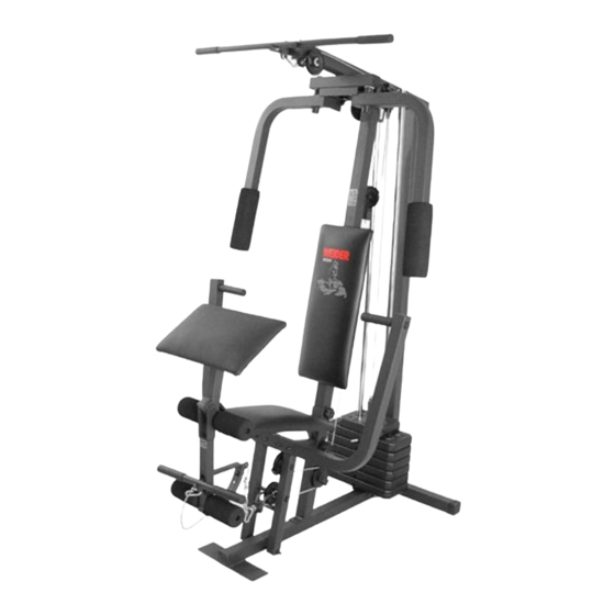
Model No. WESY19511
Serial No.
USER'S MANUAL
Write the serial number in the
space above for reference.
Serial Number Decal
QUESTIONS?
As a manufacturer, we are com-
mitted to providing complete
customer satisfaction. If you
have questions, or find there are
missing or damaged parts, we
will guarantee you complete sat-
isfaction through direct assis-
tance from our factory.
TO AVOID DELAYS, PLEASE
CALL DIRECT TO OUR TOLL-
FREE CUSTOMER HOT LINE.
The trained technicians on our
customer hot line will provide
immediate assistance, free of
charge to you.
CUSTOMER HOT LINE:
1-800-999-3756
Mon.–Fri., 6 a.m.–6 p.m. MST
CAUTION
Visit our website at
Read all precautions and instruc-
www.weiderfitness.com
tions in this manual before using
this equipment. Save this manual
new products, prizes,
for future reference.
fitness tips, and much more!
Advertisement
Table of Contents

Related Manuals for Weider 8525


Summary of Contents for Weider 8525
- Page 1 All manuals and user guides at all-guides.com Model No. WESY19511 Serial No. USER'S MANUAL Write the serial number in the space above for reference. Serial Number Decal QUESTIONS? As a manufacturer, we are com- mitted to providing complete customer satisfaction. If you have questions, or find there are missing or damaged parts, we will guarantee you complete sat-...
-
Page 2: Table Of Contents
LIMITED WARRANTY ............Back Cover Note: A PART IDENTIFICATION CHART is attached to the center of this manual. Remove the PART IDENTIFICATION CHART before beginning assembly. WEIDER is a registered trademark of ICON Health & Fitness, Inc. -
Page 3: Important Precautions
All manuals and user guides at all-guides.com IMPORTANT PRECAUTIONS WARNING : To reduce the risk of serious injury, read the following important precautions before using the weight system. 1. Read all instructions in this manual and in 12. Make sure that the cables remain on the pul- the accompanying literature before using the leys at all times. -
Page 4: Before You Begin
The model number is WESY19511. The improve your cardiovascular system, the WEIDER ® serial number can be found on a decal attached to the 8525 will help you to achieve the specific results you weight system (see the front cover of this owner's want. manual). -
Page 5: Assembly
All manuals and user guides at all-guides.com ASSEMBLY • For help identifying small parts, use the PART Make Things Easier for Yourself IDENTIFICATION CHART at the center of this manual. Everything in this manual is designed to ensure that the weight system can be assembled suc- The following tools (not included) are required cessfully by anyone. - Page 6 All manuals and user guides at all-guides.com 2. Slide the Front Upright (42) onto the M8 x 63mm Carriage Bolts (1) in the Base (4). Hand tighten an M8 Nylon Locknut (3) onto each Carriage Bolt. Do not tighten the Nylon Locknuts yet. Press a 25mm Square Inner Cap (65) into the Front Upright (42).
- Page 7 All manuals and user guides at all-guides.com 5. Press the Weight Tube Bumper (64) into the end of the Weight Tube (63). Insert the Weight Tube Holes into the stack of Weights (25). Be sure that the pins on the Weight Tube are resting in the pin grooves in the upper Weight.
- Page 8 All manuals and user guides at all-guides.com 8. Press a 38mm Square Inner Cap (44) into the top of a Press Arm (46). Press a 25mm Round Inner Cap (49) into each end of the handle on the Press Arm. Attach the Press Arm (46) to one side of the Press Frame (17) with two M8 x 62mm Bolts (22) and two M8 Nylon Locknuts (3).
- Page 9 All manuals and user guides at all-guides.com Cable Assembly 11. During steps 11 through 24, refer to the CABLE DIAGRAM on page 20 of this manual to verify proper cable routing. Before beginning this sec- tion, identify the Long Cable (23) and the Short Cable (58) by comparing the lengths of the cables.
- Page 10 All manuals and user guides at all-guides.com 15. Route the Long Cable (23) around the “V”-Pulley (6) on the Right Arm (48). Be sure that the Cable is in the groove of the “V”-Pulley and that the Long Cable Trap (50) is turned to hold the Cable in place.
- Page 11 All manuals and user guides at all-guides.com 19. Locate the Short Cable (58). Lay the Short Cable in the bracket on the Base (4). Attach the 90mm Pulley (15) to the bracket with an M10 x 45mm Bolt (12) and an M10 Nylon Locknut (21). Be sure that the end of the Cable with the ball is on the indicated side of the bracket.
- Page 12 All manuals and user guides at all-guides.com 22. Route the Short Cable (58) around the 90mm Pulley (15) attached to the upper hole in the Front Upright (42). See the inset drawing. Be sure that the Cable Trap (66) is turned to hold the Cable in place and that the Cable is routed around the Pulley as shown.
- Page 13 All manuals and user guides at all-guides.com 24. Attach the Long Cable (23) to the Small “U”- Bracket (67) with an M8 Nylon Locknut (3) and an M8 Washer (8). See the inset drawing. Do not overtighten the Nylon Locknut; it should be threaded onto the end of the Cable only a couple of turns, as shown.
- Page 14 All manuals and user guides at all-guides.com 26. Press a 38mm Square Inner Cap (32) into the Seat Frame (36). Insert the M6 x 50mm Carriage Bolt (38) into the center hole in the Seat Plate (37). Attach the Seat Plate to the Seat (13) with two M6 x 16mm Screws (18).
- Page 15 All manuals and user guides at all-guides.com 29. Press a 19mm Round Inner Cap (34) into each end of both Pad Tubes (28). Insert one Pad Tube (28) into the Seat Frame (36). Slide a Foam Pad (30) onto each end of the Pad Tube.
-
Page 16: Adjustments
All manuals and user guides at all-guides.com ADJUSTMENTS The instructions below describe how each part of the weight system can be adjusted. Refer to the exercise guide accompanying this manual to see how the weight system should be set up for each exercise. IMPOR- TANT: When attaching the lat bar or nylon strap, make sure that the attachments are in the correct start- ing position for the exercise to be performed. - Page 17 All manuals and user guides at all-guides.com ATTACHING THE LEG LEVER TO THE LOW PULLEY STATION To use the Leg Lever (29), the seat must be attached to the front upright (see ATTACHING AND REMOV- ING THE SEAT, on page 16). Attach the Short Cable (58) to the indicated M10 Eyebolt (35) with a Cable Clip (53).
-
Page 18: Weight Resistance Chart
All manuals and user guides at all-guides.com WEIGHT RESISTANCE CHART This chart shows the approximate weight resistance at each station. “Top” refers to the 6.5 lb. top weight. The other numbers refer to the 12.5 lb. weight plates. Weight resistance shown for the butterfly arm station is for each butterfly arm. -
Page 19: Troubleshooting And Maintenance
All manuals and user guides at all-guides.com TROUBLESHOOTING AND MAINTENANCE Inspect and tighten all parts each time you use the weight system. Replace any worn parts immediately. The weight system can be cleaned using a damp cloth and mild non-abrasive detergent. Do not use solvents. TIGHTENING THE CABLES Woven cable, the type of cable used on the weight system, can stretch slightly when it is first used. -
Page 20: Cable Diagram
All manuals and user guides at all-guides.com CABLE DIAGRAM The cable diagram below shows the proper routing of the Short Cable (58) and the Long Cable (23). Use the diagram to be sure that the two cables and the cable traps have been assembled correctly. If the cables have not been correctly routed, the weight system will not function properly and damage may occur. - Page 21 All manuals and user guides at all-guides.com NOTES...
-
Page 22: Part List
All manuals and user guides at all-guides.com PART LIST—Model No. WESY19511 R0802B Key No. Qty. Description Key No. Qty. Description M8 x 63mm Carriage Bolt Front Upright M6 Nylon Locknut M6 x 65mm Screw M8 Nylon Locknut 38mm Square Inner Cap Base Large Foam Pad Stabilizer... -
Page 23: Exploded Drawing
All manuals and user guides at all-guides.com EXPLODED DRAWING—Model No. WESY19511 R0802B 43 10... -
Page 24: Ordering Replacement Parts
Friday, 6 a.m. until 6 p.m. Mountain Time (excluding holidays). To help us assist you, please be pre- pared to give the following information: 1. The MODEL NUMBER of the product (WESY19511) 2. The NAME of the product (WEIDER ® 8525 weight system) 3. - Page 25 All manuals and user guides at all-guides.com REMOVE THIS PART IDENTIFICATION CHART FROM THE MANUAL This chart is provided to help you identify the small parts used in assembly. Important: Some parts may have been pre-assembled for shipping purposes; if you cannot find a part in the parts bags, check to see if it has been pre-assembled.
- Page 26 All manuals and user guides at all-guides.com PART IDENTIFICATION CHART—Model No. WESY19511 R0802B M6 Nylon Locknut (2) M8 x 45mm Bolt (72) M8 Nylon Locknut (3) M6 x 50mm Screw (24) M6 x 65mm Screw (43) M10 Nylon Locknut (21) M8 x 62mm Bolt (22) M6 Washer (10) M8 x 63mm Carriage Bolt (1)
- Page 27 All manuals and user guides at all-guides.com 28mm x 63mm Plastic Bushing (74) 25mm x 22mm Plastic Bushing (75) 25mm Retainer (69) M10 x 50mm Bolt (12) M10 x 45mm Bolt (80) M6 x 50mm Carriage Bolt (38) M6 x 16mm Screw (18) M10 x 60mm Bolt (7) M10 x 80mm Bolt (16) M10 x 90mm Bolt (77)
- Page 28 All manuals and user guides at all-guides.com M10 Eyebolt (35) 25mm Round Cover Cap (70) 19mm Round Inner Cap (34) 25mm Round Inner Cap (49) 13mm x 19mm Spacer (61) 25mm Square Inner Cap (65) 50mm Square Inner Cap (27) 38mm Square Inner Cap (44) 38mm Square Inner Cap (32) 50mm Square Outer Cap (51)
Need help?
Do you have a question about the 8525 and is the answer not in the manual?
Questions and answers