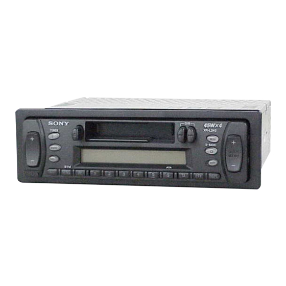
Sony XR-L240 Service Manual
Fm/mw/lw cassette car stereo
Hide thumbs
Also See for XR-L240:
- Operating instructions manual (92 pages) ,
- Service manual (36 pages) ,
- Quick start quide (4 pages)
Table of Contents
Advertisement
Quick Links
SERVICE MANUAL
Ver 1.2 2002.11
Cassette player section
Tape track
Wow and flutter
Frequency response
Signal-to-noise ratio
Tuner section
F M
Tuning range
Aerial terminal
Intermediate frequency
Usable sensitivity
Selectivity
Signal-to-noise ratio
Harmonic distortion at 1 kHz
Separation
Frequency response
M W / L W
Tuning range
Aerial terminal
Intermediate frequency
Sensitivity
Sony Corporation
9-873-349-03
2002K0500-1
e Vehicle Company
C 2002.11
Published by Sony Engineering Corporation
All manuals and user guides at all-guides.com
SPECIFICATIONS
4-track 2-channel stereo
0.13 % (WRMS)
30 – 15,000 Hz
55 dB
87.5 – 108.0 MHz
External aerial connector
10.7 MHz
11 dBf
75 dB at 400 kHz
62 dB (stereo),
68 dB (mono)
0.7 % (stereo),
0.5 % (mono)
33 dB at 1 kHz
30 – 15,000 Hz
MW: 531 – 1,602 kHz
LW: 153 – 279 kHz
External aerial connector
10.7 MHz/450 kHz
MW: 30 µV
LW: 50 µV
FM/MW/LW CASSETTE CAR STEREO
XR-L240
Model Name Using Similar Mechanism
Tape Transport Mechanism Type
Power amplifier section
Outputs
Speaker outputs
(sure seal connectors)
Speaker impedance
4 – 8 ohms
Maximum power output 45 W × 4 (at 4 ohms)
General
Outputs
Power aerial relay control
lead
Bass ±9 dB at 100 Hz
Tone controls
Treble ±9 dB at 10 kHz
Power requirements
12 V DC car battery
(negative earth)
Approx. 178 × 50 × 178 mm
Dimensions
(w/h/d)
Approx. 182 × 53 × 161 mm
Mounting dimensions
(w/h/d)
Mass
Approx. 1.2 kg
Supplied accessories
Parts for installation and
connections (1 set)
Front panel case (1)
Design and specifications are subject to change
without notice.
AEP Model
UK Model
NEW
MG-36SZ12-32
Advertisement
Table of Contents

Subscribe to Our Youtube Channel
Related Manuals for Sony XR-L240


Summary of Contents for Sony XR-L240
- Page 1 LW: 153 – 279 kHz without notice. Aerial terminal External aerial connector Intermediate frequency 10.7 MHz/450 kHz MW: 30 µV Sensitivity LW: 50 µV FM/MW/LW CASSETTE CAR STEREO Sony Corporation 9-873-349-03 2002K0500-1 e Vehicle Company C 2002.11 Published by Sony Engineering Corporation...
-
Page 2: Table Of Contents
All manuals and user guides at all-guides.com XR-L240 Ver 1.2 SERVICING NOTE TABLE OF CONTENTS TYPE A/B DISCRIMINATION In this set with following serial No. or later IC500 on MAIN board has been changed in the midway of production. With the conse-... -
Page 3: General
All manuals and user guides at all-guides.com XR-L240 SECTION 1 This section is extracted from instruction manual. GENERAL Location of controls Setting the clock The clock uses a 24-hour digital indication. Example: To set the clock to 10:08 Press (DSPL) for two seconds. -
Page 4: Installation
All manuals and user guides at all-guides.com XR-L240 Installation Installation Installation Installazione Montage Precautions Vorsichtsma§nahmen Pr cautions Precauzioni Voorzorgsmaatregelen •Choose the installation location •Wählen Sie den Einbauort sorgfältig so •Choisir soigneusement l’emplacement •Scegliere con attenzione la posizione •Kies de installatieplaats zorgvuldig carefully so that the unit will not aus, daß... -
Page 5: Connections
All manuals and user guides at all-guides.com XR-L240 Connections Anschluß Connexions Collegamenti Aansluitingen Cautions Vorsicht Précautions Attenzione Let op! •Dieses Gerät ist ausschließlich für den •Cet appareil est conçu pour •Questo apparecchio è stato progettato •Dit apparaat is ontworpen voor •This unit is designed for negative earth... - Page 6 All manuals and user guides at all-guides.com XR-L240 Connection diagram Anschlußdiagramm Schémas de connexion Diagramma di from a car aerial* von Autoantenne* collegamento de l’antenne de la voiture* dall’antenna dell’auto* Aansluitschema van een auto-antenne* Fuse (10A) Sicherung (10 A) Fusible (10 A)
- Page 7 All manuals and user guides at all-guides.com XR-L240 Cautions •Cautionary notice for handling the bracket 1. Handle the bracket carefully to avoid injuring your fingers. •Remove the protection collar 6 before installing. Sicherheitshinweise •Sicherheitshinweis zum Umgang mit der Halterung 1.
-
Page 8: Disassembly
All manuals and user guides at all-guides.com XR-L240 SECTION 2 DISASSEMBLY • This set can be disassembled in the order shown below. 2-1. DISASSEMBLY FLOW Note 1: The process described in can be performed in any order. Note 2: Without completing the process described in , the next process can not be performed. -
Page 9: Mechanism Deck (Mg-36Sz12-32)
All manuals and user guides at all-guides.com XR-L240 2-3. MECHANISM DECK (MG-36SZ12-32) 2 two screws (BTP2.6 × 6) 2 two screws (BTP2.6 × 6) 1 connector (CN350) 3 mechanism deck (MG-36SZ12-32) 1 connector (CN300) 2-4. MAIN BOARD 3 two screws 2 two ground point screws (BTP2.6 ×... -
Page 10: Heat Sink
All manuals and user guides at all-guides.com XR-L240 2-5. HEAT SINK 1 two screws 2 heat sink (PTT2.6 × 10) 1 five screws (PTT2.6 × 10) 2-6. BRACKET (MD) 1 claw 1 claw 3 bracket (MD) 1 claw 2 four screws... -
Page 11: Motor (Capstan/Reel) (M901)
All manuals and user guides at all-guides.com XR-L240 2-7. MOTOR (CAPSTAN/REEL) (M901) 2 main belt 3 sub belt (C) 1 two screws (P2 × 2.5) 4 motor (capstan/reel) (M901) Note : When installing motor, adjust the screw and screw hole of motor. -
Page 12: Head (Playback) (Hp901)
All manuals and user guides at all-guides.com XR-L240 2-9. HEAD (PLAYBACK) (HP901) 2 screw (PTT2 × 4) 3 FF/REV lever section 1 screw (P2 × 3) 7 PSW (reel) B 9 screw (P2 × 4) 8 HP roller (A) 0 SPG support plate... -
Page 13: Mechanical Adjustments
All manuals and user guides at all-guides.com XR-L240 SECTION 3 SECTION 4 MECHANICAL ADJUSTMENTS ELECTRICAL ADJUSTMENTS TEST MODE 1. Clean the following parts with a denatured-alcohol-moistened swab: This set have the test mode function. In the test mode, FM RDS S-... -
Page 14: Tape Deck Section
All manuals and user guides at all-guides.com XR-L240 Adjustment Location: PB head TAPE DECK SECTION 0 dB= 0.775 V 1. The adjustments should be performed in the order given in this service manual. 2. The adjustments should be performed for both L-CH and R-CH. -
Page 15: Tuner Section
All manuals and user guides at all-guides.com XR-L240 FM Auto Seek/Stop Level Adjustment TUNER SECTION Setting: [TUNER] button: FM 0 dB=1 µV 0.1 µ F FM RF signal dummy Cautions during repair generator antenna When the tuner unit is defective, replace it by a new one be- antenna 50 Ω... - Page 16 All manuals and user guides at all-guides.com XR-L240 FM Stereo Separation Adjustment MW Auto Seek/Stop Level Adjustmant Setting: Make this adjustment after “FM Auto Seek/Stop Level Adjust- [TUNER] button: FM ment”. Setting: FM RF signal level meter [TUNER] button: MW...
- Page 17 All manuals and user guides at all-guides.com XR-L240 Adjustment Location: – Set Upper View – Tape Speed Adjustment TU100 FM Auto Seek/Stop Level Adjustment FM Stereo Separation Adjustment MW Auto Seek/Stop Level Adjustment RV100 FM RDS S-Meter Adjustment...
-
Page 18: Diagrams
All manuals and user guides at all-guides.com XR-L240 SECTION 5 DIAGRAMS 5-1. NOTE FOR PRINTED WIRING BOARDS AND SCHEMATIC DIAGRAMS Note on Printed Wiring Board: Note on Schematic Diagram: • All capacitors are in µF unless otherwise noted. pF: µµF •... -
Page 19: Printed Wiring Board - Main Board
All manuals and user guides at all-guides.com XR-L240 Ver 1.2 5-2. PRINTED WIRING BOARD – MAIN Board – • Refer to servicing note (page 2) for discrimination of TYPE A/B. • Semiconductor Location ANT100 Ref. No. Location (FM/AM ANTENNA) D150... - Page 20 All manuals and user guides at all-guides.com XR-L240 5-3. SCHEMATIC DIAGRAM – MAIN Board (1/2) – • See page 24 for Waveforms. • See page 24 for IC Block Diagram. (Page 21) (Page 23)
-
Page 21: Schematic Diagram - Main Board (1/2)
All manuals and user guides at all-guides.com XR-L240 Ver 1.2 5-4. SCHEMATIC DIAGRAM – MAIN Board (2/2) – • See page 24 for IC Block Diagram. • Refer to servicing note (page 2) for discrimination of TYPE A/B. IC500 TA8272H... -
Page 22: Printed Wiring Board - Control Board
All manuals and user guides at all-guides.com XR-L240 5-5. PRINTED WIRING BOARD – CONTROL Board – CONTROL BOARD (COMPONENT SIDE) D934, S971 S969, 976 S974 S958 S969 S976 D930, D910 – 918, 920 – 925, 930 – 934 S958, 974... -
Page 23: Schematic Diagram - Control Board
All manuals and user guides at all-guides.com XR-L240 5-6. SCHEMATIC DIAGRAM – CONTROL Board – • See page 24 for Waveform. (Page 20) - Page 24 All manuals and user guides at all-guides.com XR-L240 • Waveforms • IC Block Diagrams – MAIN Board – – CONTROL Board – – MAIN Board – IC200 SAA6588T-118 1 IC200 4 (OSCO) 4 IC900 ud (OSC) POWER SUPPLY PAUSE 2.6 Vp-p 2.4 Vp-p...
-
Page 25: 5-7. Ic Pin Function Description
All manuals and user guides at all-guides.com XR-L240 5-7. IC PIN FUNCTION DESCRIPTION • MAIN BOARD IC1 MN101C49KTL (SYSTEM CONTROLLER) Pin No. Pin Name Description VREF – — Reference voltage (0V) terminal (for A/D converter) FM and AM signal meter voltage detection input from the FM/AM tuner unit (A/D input) 3 to 6 —... - Page 26 All manuals and user guides at all-guides.com XR-L240 Pin No. Pin Name Description — Not used Bus clock signal output to the RDS decoder VOL-SO Serial data output to the electrical volume VOL-CE Chip enable signal output to the electrical volume “H” active...
-
Page 27: Exploded Views
All manuals and user guides at all-guides.com XR-L240 Ver 1.1 SECTION 6 EXPLODED VIEWS NOTE: • -XX and -X mean standardized parts, so they • Items marked “*” are not stocked since they may have some difference from the original are seldom required for routine service. -
Page 28: 6-2. Front Panel Section
All manuals and user guides at all-guides.com XR-L240 6-2. FRONT PANEL SECTION not supplied (CONTROL board) LCD900 Ref. No. Part No. Description Remark Ref. No. Part No. Description Remark 3-224-914-01 BUTTON (4-6) (4. 5. 6. TA. PTY. DSPL) 3-236-752-01 BUTTON (SEEK) (+ SEEK MANU -) 3-224-906-01 BUTTON (1-3) (ATT. -
Page 29: Mechanism Deck Section (Mg-36Sz12-32)
All manuals and user guides at all-guides.com XR-L240 Ver 1.2 6-3. MECHANISM DECK SECTION (MG-36SZ12-32) HP901 M901 S902 S903 S901 Ref. No. Part No. Description Remark Ref. No. Part No. Description Remark 3-224-920-01 BRACKET (MD) 3-045-891-01 PINCH ARM (F) 3-045-943-01 MAIN BELT... -
Page 30: Electrical Parts List
All manuals and user guides at all-guides.com XR-L240 SECTION 7 CONTROL ELECTRICAL PARTS LIST NOTE: When indicating parts by reference • Due to standardization, replacements in the • Items marked “*” are not stocked since they number, please include the board. - Page 31 All manuals and user guides at all-guides.com XR-L240 CONTROL MAIN Ref. No. Part No. Description Remark Ref. No. Part No. Description Remark R902 1-216-049-11 RES-CHIP 1/10W R903 1-216-049-11 RES-CHIP 1/10W C161 1-124-257-00 ELECT 2.2uF R904 1-216-049-11 RES-CHIP 1/10W C164 1-162-970-11 CERAMIC CHIP 0.01uF...
- Page 32 All manuals and user guides at all-guides.com XR-L240 Ver 1.2 MAIN Ref. No. Part No. Description Remark Ref. No. Part No. Description Remark C422 1-124-257-00 ELECT 2.2uF C423 1-164-677-11 CERAMIC CHIP 0.033uF < CONNECTOR > C424 1-107-826-11 CERAMIC CHIP 0.1uF...
- Page 33 All manuals and user guides at all-guides.com XR-L240 MAIN Ref. No. Part No. Description Remark Ref. No. Part No. Description Remark < TRANSISTOR > 1-247-807-31 CARBON 1/4W Q120 8-729-920-21 TRANSISTOR DTC314TKH04 1-216-025-11 RES-CHIP 1/10W Q121 8-729-920-21 TRANSISTOR DTC314TKH04 1-247-807-31 CARBON...
- Page 34 All manuals and user guides at all-guides.com XR-L240 Ver 1.2 MAIN Ref. No. Part No. Description Remark Ref. No. Part No. Description Remark R359 1-216-115-00 METAL CHIP 560K 1/10W R702 1-249-421-11 CARBON 2.2K 1/4W R360 1-249-393-11 CARBON 1/4W R703 8-719-200-82 DIODE 11ES2...
- Page 35 All manuals and user guides at all-guides.com XR-L240 Ref. No. Part No. Description Remark Ref. No. Part No. Description Remark S903 1-771-927-11 SWITCH (LEAF) (TAPE DETECT) ************************************************************ ************** HARDWARE LIST ************** 7-685-792-09 SCREW +PTT 2.6X6 (S) 7-685-794-09 SCREW +PTT 2.6X10 (S) 7-685-106-19 SCREW +P 2X10 TYPE2 NON-SLIT 7-621-775-10 SCREW +B 2.6X4...
- Page 36 All manuals and user guides at all-guides.com XR-L240 REVISION HISTORY Clicking the version allows you to jump to the revised page. Also, clicking the version at the upper right on the revised page allows you to jump to the next revised page.
Need help?
Do you have a question about the XR-L240 and is the answer not in the manual?
Questions and answers