Sony XR-L240 Service Manual
Fm/mw/lw cassette car stereo
Hide thumbs
Also See for XR-L240:
- Operating instructions manual (92 pages) ,
- Service manual (36 pages) ,
- Quick start quide (4 pages)
Advertisement
SERVICE MANUAL
Ver 1.0 2001.10
Cassette player section
Tape track
Wow and flutter
Frequency response
Signal-to-noise ratio
Tuner section
F M
Tuning range
Aerial terminal
Intermediate frequency
Usable sensitivity
Selectivity
Signal-to-noise ratio
Harmonic distortion at 1 kHz
Separation
Frequency response
M W / L W
Tuning range
Aerial terminal
Intermediate frequency
Sensitivity
Sony Corporation
9-873-349-01
2001J0500-1
e Vehicle Company
C 2001.10
Published by Sony Engineering Corporation
SPECIFICATIONS
Power amplifier section
4-track 2-channel stereo
Outputs
0.13 % (WRMS)
30 – 15,000 Hz
Speaker impedance
Maximum power output 45 W × 4 (at 4 ohms)
55 dB
General
Outputs
87.5 – 108.0 MHz
Tone controls
External aerial connector
10.7 MHz
Power requirements
11 dBf
75 dB at 400 kHz
Dimensions
62 dB (stereo),
68 dB (mono)
Mounting dimensions
0.7 % (stereo),
Mass
0.5 % (mono)
Supplied accessories
33 dB at 1 kHz
30 – 15,000 Hz
MW: 531 – 1,602 kHz
Design and specifications are subject to change
LW: 153 – 279 kHz
without notice.
External aerial connector
10.7 MHz/450 kHz
MW: 30 µV
LW: 50 µV
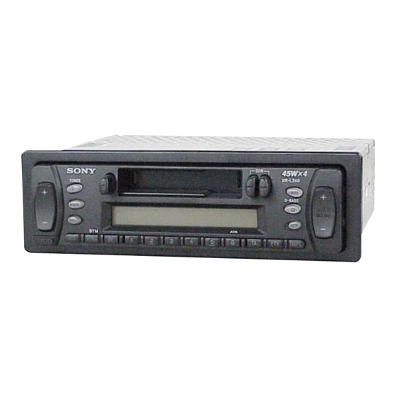
FM/MW/LW CASSETTE CAR STEREO
XR-L240
Model Name Using Similar Mechanism
Tape Transport Mechanism Type
Speaker outputs
(sure seal connectors)
4 – 8 ohms
Power aerial relay control
lead
Bass ±9 dB at 100 Hz
Treble ±9 dB at 10 kHz
12 V DC car battery
(negative earth)
Approx. 178 × 50 × 178 mm
(w/h/d)
Approx. 182 × 53 × 161 mm
(w/h/d)
Approx. 1.2 kg
Parts for installation and
connections (1 set)
Front panel case (1)
AEP Model
UK Model
NEW
MG-36SZ12-32
Advertisement
Table of Contents

Related Manuals for Sony XR-L240


Summary of Contents for Sony XR-L240
- Page 1 LW: 153 – 279 kHz without notice. Aerial terminal External aerial connector Intermediate frequency 10.7 MHz/450 kHz MW: 30 µV Sensitivity LW: 50 µV FM/MW/LW CASSETTE CAR STEREO Sony Corporation 9-873-349-01 2001J0500-1 e Vehicle Company C 2001.10 Published by Sony Engineering Corporation...
- Page 2 XR-L240 5-2. PRINTED WIRING BOARD – MAIN Board – • Semiconductor Location Ref. No. Location ANT100 (FM/AM ANTENNA) D150 F901 D250 MAIN BOARD FL– D251 CN700 RL– D252 C500 CN700 R853 (POWER) D290 RR– D351 FR– D450 IC500 D500 C467...
- Page 3 XR-L240 5-3. SCHEMATIC DIAGRAM – MAIN Board (1/2) – • • See page 24 for Waveforms. See page 24 for IC Block Diagram. (Page 21) (Page 23)
- Page 4 XR-L240 5-4. SCHEMATIC DIAGRAM – MAIN Board (2/2) – • See page 24 for IC Block Diagram. (Page 20)
- Page 5 XR-L240 5-5. PRINTED WIRING BOARD – CONTROL Board – CONTROL BOARD (COMPONENT SIDE) D934, S971 S969, 976 S974 S958 S976 S969 D930, D910 – 918, 920 – 925, 930 – 934 S958, 974 S959 S972 TUNER D-BASS D930 S956 MODE...
- Page 6 XR-L240 5-6. SCHEMATIC DIAGRAM – CONTROL Board – • See page 24 for Waveform. (Page 20)
Need help?
Do you have a question about the XR-L240 and is the answer not in the manual?
Questions and answers